Table of Contents
Advertisement
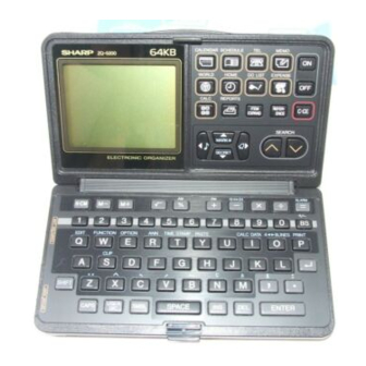
STANDARD FUNCTION
0.45 0.04
CPU: SC6201 5B02
Display: LH5073A and LH5074F
Mask ROM: UPD23C2001 GW302
Regulator: SC1771 1 YDA
SRAM: M5256FP15L
Low battery ditecter: MN1 280P
RTC: SEK6115B
P O W E R S U P P L Y 1 AC: X 1
Main power supply:
6 Vdc lithium batteries (CR2032 x 2)
Memory backup power:
3 Vdc lithium battery (CR2032 x 1)
AC ADAPTOR
RECHARGEABLE
POWER
0.08 W
CONSUMPTION
AUTO POWER
Approx. 6 minutes
OFF TIME
MEMORY
Yes
PROTECT
Open: 145(W) x 160(D) x 8.9(H) mm.
Closed: 145(W) x 80(D) x 17.8(H) mm.
Weight
Approx. 1759 (including batteries)
CALCULATIONS 1
addition, subtraction, multiplication, division;
constant, square root, percent, memory
calculation, estimation
Accessories
Lithium batteries (CR2032 x 3)
Operation manual
10 digits
16 dinits
(8 lines)
96 x 64 dot matrix liquid crystal
(with 5 x 7 dot characters)
12 columns 4 lines
(with 8 x 16 dot characters)
Electronic notebook
section
DC: 0
Clock
Operating time
SHARP CORPORATION
KEY SYSTEM: Rubber key
service only.
The contents are subject to change without notice.
Advertisement
Table of Contents

Related Manuals for Sharp ZQ-5000


Summary of Contents for Sharp ZQ-5000
- Page 1 Weight Approx. 1759 (including batteries) Operating time CALCULATIONS 1 addition, subtraction, multiplication, division; constant, square root, percent, memory calculation, estimation Accessories Lithium batteries (CR2032 x 3) Operation manual SHARP CORPORATION service only. The contents are subject to change without notice.
- Page 2 ZQ-5000 Terminal No. Signal name Input/Output Descriptions output Ceramic oscillation output Input Ceramic oscillation output CR oscillation output Input CR oscillation input output Display power v c c Power Power (+) RESET Input Power TEST Input Input Input Data bus...
- Page 3 ZQ-5200 Descriptions Terminal No. Signal name Input Input Low battery control signal output output Multi-language select signal Not used. Multi-language select signal output RTC serial clock sianal RTC serial IN signal Input RTC timer reset siqnal output control signal 2. LCD drivers LH5073A and LH5074F LCD drivers LH5073A and LH5074F, as display common drivers, respectively include 32 drive circuits.
-
Page 4: Terminal Arrangement
H H H H 16 15 14 13 13 14 15 16 17 1 97 98 32 name (Note) NC : Not used terminal... - Page 6 7-Q-5200 Common output Segment output Common output Segment output Common output Segment output Common output Segment output Common output Segment output Segment output (Note *) Mark ‘ *” means LH5073A signal name, and LH5074F terminal is not used. LCD driver (Master) M...
-
Page 7: Operational Description
Segment driver Supplied from IN OUT IN OUT IN OUT IN OUl used in pairs with LH5073A. The display section power VFF, liquid crystal drive power VDP,VA, VM, and synchronization signal HA of VM and display divider are supplied from the output terminals of the same names of LH5073A. - Page 8 HA output - input HA32 cycles HA32 cycles , _ _.., (Note) Valuessf VA, VM, and V!3 are TYP values when VDP is set to 1OV. 3. RTC (SEKGI 15B) A L A R M )5 11 (c2 o s c 2 )7 9 (vs3...
- Page 9 5. Low battery detection circuits This is used to produce power for RTC (SMC6115F). (6V + 3V) The ZQ-5000/5200 is equipped with the following two circuits for low battery detection: The main battery voltage detection circuit @ detects the battery volt- age during operation of the unit.
-
Page 10: Circuit Description
ZQ-5000 After Smsec of E8’ s becoming high, DIS becomes low. After I oopsec, the back-up battery low voltage is detected. When LBIC is high, it is normal. When LBIC is low, KIO becomes high to turn off the display of <ATTENTION>... -
Page 11: Current Check
7. Conduction test 9. Note for battery replacement Check conduction be- tween the key fixing Batteries used in the Organizer: plate and the fixing Model angle. CR2032 Unit operation Max. 25 R CR2032 Memory backup The standard built-in clock and world city clock are powered by the operating batteries. -
Page 12: Replacing The Memory Backup Battery
ZQ-5200 For example, if you replace the battery in December, 1996, write: to turn the power off. 2. Press the rear cover and slide to remove it. Battery replacement switch Extremes of temperature will shorten battery life and endan- ger the memory information. When replacing the memory backup battery, make sure that the rating batteries are not depleted. - Page 13 Pattern A To protect user data when servicing, abnormal ZQ-500015200 is con- nected with normal ZQ-5000/5200 with transmission cable and user data are transmitted by command input from the abnormal set to the normal set. After completion of servicing, the data are restored from the normal set to the repaired set.
-
Page 14: Contrast Adjustment
ZQ-5200 13. Low battery check, advancement check Perform the low battery check and advancement check according to the following table. Power source Operation Display Standards Connect the power source and the advance- ment meter to the set. *’ Turn on power I and II. The calendar is displayed. - Page 15 VERIFY: 16. Data communications between Used to verify the data item displayed by the sending unit or to verify all of the data sent in the pertrnent two Organizers mode. Select “ 3 VERIFY” for the receiving unit and “1 SEND” for the sending unit.
-
Page 16: Verifying Data
4. Select “ 2 RECEIVE” on the receiving unit. 2. Display the “ UNIT TO UNIT” menu on the receivina unit. (Make sure that both the sending and receiving units are set to the 5. Select “1 SEND” on the sending unit. same mode.) 3. -
Page 17: When Trouble Occurs
ZQ-5000 ZQ-5200 to transfer “ TAYLOR” in the TEL1 mode from a ZQ When transferring data from EL series to ZQ series Organizers series Organizer to an EL series Organizer. Non-English characters (e.g. A) are changed to small letters, 1. Display the item on the sending unit (ZQ series). -
Page 18: Troubleshooting
18. Troubleshooting Hold the spring with a squeezer If the Organizer malfunctions, go over the following checklist before and insert into the chassis. sending it out for repairs: Chassis If . Then you should .,. Nothing appears on the Replace the batteries. (Refer to after you have pressed page 10.) The display contrast is insuffi-... - Page 19 The key decoration panel of the ZQ-5000 is marked with stripe lid. pattern in the numeric key section, and that of the ZQ-5200 has no pattern. Attach two spacers to adjust warp of the hinge chassis A.
- Page 20 Perform the following procedure with the set closed. lid. 00 has careful to the direction of the LCD spacer.) reflection plate side. attach it. Fold in front of the duplex tape. .,’ ’ slider to the main side. tape. Fixing tape apply the fixing tape to the heat seal section.
- Page 21 ZQ-5000 ZQ-5200 v c c 0 2 DTCl44WU...
- Page 22 Battery replacement switch CAPS...
- Page 25 ZQ-5200 ‘ A I 44EK v c c REG. R T C...
- Page 26 Battery replacement switch SHIFT ON I 0 3 OTA I44EU S - R A M...
- Page 27 Solder and short the 3pin side lead...
- Page 29 Da Key fixing plate Battery case Contact Slider lock spring rubber 1501th Spacer (ZQ-5000 : Applicable since the 8 PSPAP1380CCZZ A ZQ-5200 : Applica,,, =lllrr Lllr , , v-rLqI VIII1,l.IOICII,lzzv v,vuucLlvlI, , 9 TLABZ3010CCZZ A Screw Display panel 0 HDECA2420CCZZ...
- Page 30 Exteriors 7 c4>39...
- Page 31 The ZQ-5000/5200 board units have different parts and different patterns according to production date. (The boards units, however, are compatible each other.) in case of a board unit trouble in a set of the first production thru 10050th production, replace the whole board unit with new one.
- Page 32 S H A R P COPYRIGHT 0 1990 BY SHARP CORPORATION All rights reserved. Printed in Japan. No part of this publication may be reproduced, stored in a retrieval system, or transmitted, in any form or by any means, electronic, mechanical, photocopying, recording, or otherwise, without prior written permission of the publisher.