
Related Manuals for Bosch Praesideo 3.5


Summary of Contents for Bosch Praesideo 3.5
- Page 1 Praesideo 3.5 Installation and User Instructions Digital Public Address and Emergency Sound System...
- Page 2 Praesideo 3.5 | Installation and User Instructions en | 2 Intentionally left blank. Bosch Security Systems | 2011-02...
-
Page 3: Disclaimer
Bosch Security Systems disclaim all warranties with regard to the information provided in these instructions. accordance with the instruction manual, may cause In no event shall Bosch Security Systems be liable for harmful interference to radio communications. Operation any special, indirect or consequential damages... - Page 4 Praesideo 3.5 | Installation and User Instructions en | 4 Intentionally left blank. Bosch Security Systems | 2011-02...
-
Page 5: Table Of Contents
Praesideo 3.5 | Installation and User Instructions | 0 | Table of Contents en | 5 Table of Contents Disclaimer ....................................3 Important Safeguards................................3 FCC Requirements Class A ..............................3 Table of Contents..................................5 Emergency Sound Systems............................. 13 EN60849: 1998 compliancy checklist ..........................15 EN54-16: 2008 compliancy checklist.......................... - Page 6 Praesideo 3.5 | Installation and User Instructions | 0 | Table of Contents en | 6 Installation ....................................110 Using the configuration menu ............................111 Configuration and operation ............................114 Technical data ..................................116 7 LBB4404/00 CobraNet Interface ............................119 Introduction ..................................119 Controls and connectors ..............................120 Rear view ....................................120...
- Page 7 Praesideo 3.5 | Installation and User Instructions | 0 | Table of Contents en | 7 12.4 Addressing ...................................194 12.5 Technical data supervision control board ........................195 12.6 Technical data loudspeaker supervision board ......................196 12.7 Technical data EOL supervision board .........................197 13 LBB4446/00 Brackets ................................198...
- Page 8 Praesideo 3.5 | Installation and User Instructions | 0 | Table of Contents en | 8 21 PRS-CSRK Remote Call Station Kit ............................240 21.1 Introduction ..................................240 21.2 Controls, connectors and indicators ..........................241 21.3 Installation ....................................248 21.4 Technical Data ..................................249 22 PRS-CSI Call Station Interface ..............................250 22.1 Introduction ..................................250...
- Page 9 Praesideo 3.5 | Installation and User Instructions | 0 | Table of Contents en | 9 31.1 Introduction ..................................295 31.2 System bus ..................................295 31.3 Dust caps .....................................296 31.4 Maximum distance ................................296 31.5 Maximum cable length ..............................297 31.6 Bending and coiling ................................298 32 Architecture ....................................299...
- Page 10 Praesideo 3.5 | Installation and User Instructions | 0 | Table of Contents en | 10 40.1 Introduction ..................................323 40.2 Starting and logging on ..............................323 40.3 Overview ....................................323 40.4 Configure section ................................324 40.5 Diagnose section ................................327 40.6 Upgrade section .................................327 41 User management ..................................328...
- Page 11 Praesideo 3.5 | Installation and User Instructions | 0 | Table of Contents en | 11 47.3 Actions ....................................386 48 Audio processing ..................................401 48.1 Introduction ..................................401 48.2 Audio processing parameters ............................401 48.3 AVC calibration ...................................403 49 Automatic volume control ................................404 49.1 Introduction ..................................404...
- Page 12 Praesideo 3.5 | Installation and User Instructions | 0 | Table of Contents en | 12 57.1 Introduction ..................................454 57.2 Requirements ..................................454 57.3 Installation ....................................454 57.4 Start .......................................454 57.5 Configuration ..................................455 57.6 Operation .....................................456 58 PC Call Server .....................................459 58.1 Introduction ..................................459 58.2 Requirements ..................................459...
-
Page 13: Emergency Sound Systems
| 13 Emergency Sound Systems Bosch Security Systems has made a great effort for the design and manufacturing of the components and also supplies all documentation that enables the assembly of a safe and high quality emergency unit in accordance with EN60849:1998, EN54-16:2008 and ISO7240-16:2007. - Page 14 Praesideo 3.5 | Installation and User Instructions | Emergency Sound Systems en | 14 List of authorized end-users Name Name Bosch Security Systems | 2011-02...
-
Page 15: En60849: 1998 Compliancy Checklist
Praesideo 3.5 | Installation and User Instructions | EN60849: 1998 en | 15 EN60849: 1998 compliancy checklist EN60849 - 4. General system requirements EN60849 - 4. 1 Principal features Requirement Compliance Signature A sound system for emergency purposes shall permit Compliant, if properly installed. - Page 16 Praesideo 3.5 | Installation and User Instructions | EN60849: 1998 en | 16 Requirement Compliance Signature All messages shall be clear, short, unambiguous Responsibility of the installer. and as far as practicable, pre-planned. Where pre-recorded messages are used they shall...
- Page 17 Praesideo 3.5 | Installation and User Instructions | EN60849: 1998 en | 17 Requirement Compliance Signature The use of these levels in descending order of priority Compliant, if properly installed. Responsibility of the will ensure that appropriate alarm signals and installer.
- Page 18 Praesideo 3.5 | Installation and User Instructions | EN60849: 1998 en | 18 EN60849 - 5. System technical requirements EN60849 - 5. 1 Speech intelligibility Requirement Compliance Signature Unless otherwise specified, the following requirement shall be satisfied: The speech intelligibility over all of an area of coverage Responsibility of the installer.
- Page 19 Praesideo 3.5 | Installation and User Instructions | EN60849: 1998 en | 19 Requirement Compliance Signature Failure of microphone, including capsule voice coil, Compliant. Fault is indicated by a control output of the pre-amplifier and essential wiring to the rest of the Network Controller, if properly installed.
- Page 20 Praesideo 3.5 | Installation and User Instructions | EN60849: 1998 en | 20 EN60849 - 5.4 Monitoring of software controlled equipment Requirement Compliance Signature The correct execution of the system software by any microprocessor shall be monitored by internal self- checking procedures and by an appropriate monitoring circuit (e.g.
- Page 21 Praesideo 3.5 | Installation and User Instructions | EN60849: 1998 en | 21 Requirement Compliance Signature In complex buildings in which actions, such as initiation Responsibility of the installer. of evacuation signals, silencing of alarm signals, etc., can be implemented at remote voice alarm equipment,...
- Page 22 Praesideo 3.5 | Installation and User Instructions | EN60849: 1998 en | 22 EN60849 - 5.7 Climate and environmental conditions Requirement Compliance Signature As all or part of the system may be installed inside or Praesideo specifications exceed the environmental outside buildings, under various climatic and requirements given by EN60849:1998.
- Page 23 Praesideo 3.5 | Installation and User Instructions | EN60849: 1998 en | 23 EN60849 - 6. Installation requirements Requirement Compliance Signature The system shall be installed in accordance with Responsibility of the installer. IEC60364 or with mandatory national or local standards.
- Page 24 Praesideo 3.5 | Installation and User Instructions | EN60849: 1998 en | 24 EN60849 - 7. Instructions for use EN60849 - 7.1 Instructions for operation Requirement Compliance Signature Instructions for the operation of the system, including Responsibility of the installer.
- Page 25 Praesideo 3.5 | Installation and User Instructions | EN60849: 1998 en | 25 EN60849 - 7.3 Maintenance EN60849 - 7.3. 1 General Requirement Compliance Signature There shall be an established and documented Responsibility of the installer to establish the procedure for the scheduled maintenance and retesting...
- Page 26 Praesideo 3.5 | Installation and User Instructions | EN60849: 1998 en | 26 Intentionally left blank. Bosch Security Systems | 2011-02...
-
Page 27: En54-16: 2008 Compliancy Checklist
Praesideo 3.5 | Installation and User Instructions | EN54-16: 2008 en | 27 EN54-16: 2008 compliancy checklist Clause / Requirement Compliance Signature 4 General requirements 4. 1 General Praesideo is compliant. 4. 1 . 1 If an optional function with requirements is... - Page 28 Praesideo 3.5 | Installation and User Instructions | EN54-16: 2008 en | 28 Clause / Requirement Compliance Signature 5 General requirements for indications 5. 1 Display and functional conditions Praesideo is compliant. 5. 1 . 1 The VACIE shall be capable of unambiguously See Clauses 6 to 9.
- Page 29 Praesideo 3.5 | Installation and User Instructions | EN54-16: 2008 en | 29 Clause / Requirement Compliance Signature 5.3 Indication on alphanumeric displays Praesideo is compliant. Where an alphanumeric display is used to display The alphanumeric display of the network controller...
- Page 30 Praesideo 3.5 | Installation and User Instructions | EN54-16: 2008 en | 30 Clause / Requirement Compliance Signature 6 The quiescent condition Any kind of system information may be displayed during the Praesideo is compliant. quiescent condition. However, no indications shall be given which could be confused with indications used in the •...
- Page 31 Praesideo 3.5 | Installation and User Instructions | EN54-16: 2008 en | 31 Clause / Requirement Compliance Signature 7 The voice alarm condition 7. 1 Reception and processing of fire signals Praesideo is compliant. 7. 1 . 1 The VACIE shall be capable of receiving and...
- Page 32 Praesideo 3.5 | Installation and User Instructions | EN54-16: 2008 en | 32 Clause / Requirement Compliance Signature 7.3 Audible warning (option with requirements) An audible warning of the voice alarm condition might be Output contacts of the Praesideo system can be the same as that for the fault warning condition.
- Page 33 Praesideo 3.5 | Installation and User Instructions | EN54-16: 2008 en | 33 Clause / Requirement Compliance Signature 7.6. 1 .2 The silencing procedure may allow for the A voice alarm call that is stopped while not being finished completion of messages in the process of being broadcast.
- Page 34 Praesideo 3.5 | Installation and User Instructions | EN54-16: 2008 en | 34 Clause / Requirement Compliance Signature 7.9 Voice alarm condition output Praesideo is compliant. (option with requirements) The VACIE may have provision for transmitting a signal that The Praesideo system transmits a signal that it is in the is in the voice alarm condition.
- Page 35 Praesideo 3.5 | Installation and User Instructions | EN54-16: 2008 en | 35 Clause / Requirement Compliance Signature 8 Fault warning condition 8. 1 Reception and processing of fault signals Praesideo is compliant. 8. 1 . 1 The VACIE shall enter the fault warning condition...
- Page 36 Praesideo 3.5 | Installation and User Instructions | EN54-16: 2008 en | 36 Clause / Requirement Compliance Signature an indication at least common to any earth fault of less All 100V lines of the Praesideo system can be supervised than 50 kΩ is capable of affecting a mandatory individually for earth faults (i.e.
- Page 37 Praesideo 3.5 | Installation and User Instructions | EN54-16: 2008 en | 37 Clause / Requirement Compliance Signature any short-circuit or interruption in the transmission path The Praesideo system does not offer this functionality between the VACIE and fire alarm devices when used directly: control inputs are supervised, but control outputs (see 7.8).
- Page 38 Praesideo 3.5 | Installation and User Instructions | EN54-16: 2008 en | 38 Clause / Requirement Compliance Signature 8.6.2 The audible indication shall be silenced automatically Since the Praesideo system does not offer automatic reset if the VACIE is automatically reset from the fault warning from the fault warning condition this requirement does not condition.
- Page 39 Praesideo 3.5 | Installation and User Instructions | EN54-16: 2008 en | 39 Clause / Requirement Compliance Signature 9 Disablement condition (option with requirements) Praesideo does not support the disablement condition. 9. 1 General requirements 9. 1 . 1 Disablements in accordance with the requirements of 9.4 shall inhibit all corresponding mandatory indications...
- Page 40 Praesideo 3.5 | Installation and User Instructions | EN54-16: 2008 en | 40 Clause / Requirement Compliance Signature 10 Voice alarm manual control (option with requirements) 10. 1 General requirements Praesideo is compliant. The VACIE may have provision for manually activating the voice alarm output condition.
- Page 41 Praesideo 3.5 | Installation and User Instructions | EN54-16: 2008 en | 41 Clause / Requirement Compliance Signature a separate light emitting indicator (the general fault The Praesideo system provides a visual indication when it is indicator), and in the fault warning condition via the fault LED of the call...
- Page 42 Praesideo 3.5 | Installation and User Instructions | EN54-16: 2008 en | 42 Clause / Requirement Compliance Signature 11 Interface to external control device(s) (option with the requirements) The VACIE may have provision for interfacing to external Praesideo is compliant.
- Page 43 Praesideo 3.5 | Installation and User Instructions | EN54-16: 2008 en | 43 Clause / Requirement Compliance Signature 12 Emergency microphone(s) (option with requirements) The VACIE may have provision for emergency The Praesideo system offers two types of emergency microphone(s). In this case the emergency microphone(s)
- Page 44 Praesideo 3.5 | Installation and User Instructions | EN54-16: 2008 en | 44 Clause / Requirement Compliance Signature where the VACIE has provision for the connection of Configuration of the emergency microphones is performed more than one emergency microphone, they shall be via the web interface of the network controller.
- Page 45 Praesideo 3.5 | Installation and User Instructions | EN54-16: 2008 en | 45 Clause / Requirement Compliance Signature 13 Design requirements 13. 1 General requirements and manufacturer's Praesideo is compliant. declarations 13. 1 . 1 The VACIE shall comply with the design...
- Page 46 Praesideo 3.5 | Installation and User Instructions | EN54-16: 2008 en | 46 Clause / Requirement Compliance Signature information on the communication parameters employed on each transmission path, recommended cable parameters for each transmission path, and fuse ratings; specified means to limit the consequences of fault (see The IUI describes the following means to limit the 13.5.2);...
- Page 47 Praesideo 3.5 | Installation and User Instructions | EN54-16: 2008 en | 47 Clause / Requirement Compliance Signature 13.4 Electrical and other design requirements Praesideo is compliant. 13.4. 1 The processing of signals shall give the highest Calls within the Praesideo system have a configured priority to the voice alarm condition.
- Page 48 Praesideo 3.5 | Installation and User Instructions | EN54-16: 2008 en | 48 Clause / Requirement Compliance Signature 13.5.3 A single short circuit or an interruption in any voice The voice alarm transmission path between distributed alarm transmission path between distributed cabinets of a...
- Page 49 Praesideo 3.5 | Installation and User Instructions | EN54-16: 2008 en | 49 Clause / Requirement Compliance Signature 13.6 Accessibility of indications and controls Praesideo is compliant. Four access levels shall be provided on the VACIE, from The Praesideo system offers three types of user accounts...
- Page 50 Praesideo 3.5 | Installation and User Instructions | EN54-16: 2008 en | 50 Clause / Requirement Compliance Signature all mandatory indications shall be visible at access level All indicators of the Praesideo system can be visible at 1 without prior manual intervention (e.g. the need to access level 1.
- Page 51 Praesideo 3.5 | Installation and User Instructions | EN54-16: 2008 en | 51 Clause / Requirement Compliance Signature 13.8.3 Mandatory indications on an alphanumeric display If the Praesideo system enters the voice alarm condition the shall be legible for at least one hour following the display of...
- Page 52 Praesideo 3.5 | Installation and User Instructions | EN54-16: 2008 en | 52 Clause / Requirement Compliance Signature 13. 1 1 Indicator testing Praesideo is compliant. All mandatory visible and audible indicators shall be Praesideo provides an ‘Indicator test’ action that can be testable by a manual operation at access level 1 or 2.
- Page 53 Praesideo 3.5 | Installation and User Instructions | EN54-16: 2008 en | 53 Clause / Requirement Compliance Signature The frequency response of all Praesideo sound paths that do not include microphones is within the specified limits of this clause, with the following remarks for the LBB4428/00.
- Page 54 Praesideo 3.5 | Installation and User Instructions | EN54-16: 2008 en | 54 Clause / Requirement Compliance Signature 13. 1 4. 1 The VACIE may have provision for at least one Each power amplifier channel of the Praesideo system has spare power amplifier.
- Page 55 Praesideo 3.5 | Installation and User Instructions | EN54-16: 2008 en | 55 Clause / Requirement Compliance Signature 14 Additional design requirements for software controlled VACIE 14. 1 General requirements and manufacturer's Praesideo is compliant. declarations In order to fulfill requirements of this European Standard the...
- Page 56 Praesideo 3.5 | Installation and User Instructions | EN54-16: 2008 en | 56 Clause / Requirement Compliance Signature details of any software tools used in the preparation of The list can be composed on request and contains the program (e.g. high level design tools, compilers, high level design tools, compilers for various processors, assemblers).
- Page 57 Praesideo 3.5 | Installation and User Instructions | EN54-16: 2008 en | 57 Clause / Requirement Compliance Signature 14.5 The storage of programs and data (see also Praesideo is compliant. Annex C) 14.5. 1 All executable code and data necessary to comply...
- Page 58 Praesideo 3.5 | Installation and User Instructions | EN54-16: 2008 en | 58 Clause / Requirement Compliance Signature 15 Marking Praesideo is compliant. The VACIE shall be marked with the following information, which shall be legible at access level 1: the number of this European Standard;...
-
Page 59: En54-16: 2008 Vacie Label
EN 54-16 or ISO 7240-16 and has clearly indicated on the VACIE label the year in which the VACIE label actually has been affixed on the cabinet. The aforementioned checklists are available in the Installation and User Instructions manual of Praesideo 3.5. The VACIE label shall be clearly visible without prior manual intervention. -
Page 60: En54-16: 2008 Products Description
Praesideo 3.5 | Installation and User Instructions | EN54-16: 2008 en | 60 EN54-16: 2008 products description EN 54-16 is a product standard governing 'Voice Alarm Control and Indicating Equipment' (VACIE) which is issued by the European Union Construction Product Directive (CPD), also known as Directive 89/106/EEC. -
Page 61: Iso7240-16: 2007 Compliancy Checklist
Praesideo 3.5 | Installation and User Instructions | ISO7240-16: 2007 en | 61 ISO7240-16: 2007 compliancy checklist Clause / Requirement Compliance Signature EN54-16 and ISO7240-16 are very similar standards. The Responsibility of the installer. The installer must use the following list gives a summary of the differences between... - Page 62 Praesideo 3.5 | Installation and User Instructions | ISO7240-16: 2007 en | 62 7.2.2 Where a voice signal is used as part of the alert Praesideo offers this functionality via its call macros. The signal, the alert signal shall precede the first pre-recorded installer must configure the call macros accordingly.
- Page 63 Praesideo 3.5 | Installation and User Instructions | ISO7240-16: 2007 en | 63 8.6 Fault-warning condition output signal The Praesideo network controller provides two predefined The s.s.c.i.e. shall have an output to transmit the fault- control outputs for audible and visual fault indicators with warning condition specified in 8.2.
- Page 64 Praesideo 3.5 | Installation and User Instructions | ISO7240-16: 2007 en | 64 Clause / Requirement Compliance Signature 13 Emergency microphone - Optional function 13. 1 General c The emergency microphone control shall mute alert and If the configured call of the emergency microphone was...
- Page 65 Praesideo 3.5 | Installation and User Instructions | ISO7240-16: 2007 en | 65 Clause / Requirement Compliance Signature 14 Design requirements 14.2 Documentation 14.2. 1 The manufacturer shall prepare installation and user documentation, which shall be submitted to the testing authority together with the s.s.c.i.e.
- Page 66 Praesideo 3.5 | Installation and User Instructions | ISO7240-16: 2007 en | 66 Clause / Requirement Compliance Signature 17 Tests All tests as asked for in the clauses of section 17 have been carried out by an accredited certification body for ISO7240-16 compliancy.
- Page 67 Praesideo 3.5 | Installation and User Instructions | ISO7240-16: 2007 en | 67 Clause / Requirement Compliance Signature 14 Design requirements 14. 1 General requirements and manufacturer's declarations 14. 1 .2 In order to assist the process of design inspection,...
- Page 68 Praesideo 3.5 | Installation and User Instructions | ISO7240-16: 2007 en | 68 Clause / Requirement Compliance Signature 17 Tests All tests as asked for in the clauses of section 17 have been carried out by an accredited certification body for ISO7240-16 compliancy.
- Page 69 Praesideo 3.5 | Installation and User Instructions | ISO7240-16: 2007 en | 69 Excluded clauses Clause / Requirement Compliance Signature EN54-16, clause 12. 1 Emergency microphone - option with requirements. Where a pre-announcement attention drawing signal is This clause is not part of ISO7240-16.
- Page 70 Praesideo 3.5 | Installation and User Instructions | ISO7240-16: 2007 en | 70 Intentionally left blank. Bosch Security Systems | 2011-02...
-
Page 71: Praesideo On Board Of Ships
Praesideo 3.5 | Installation and User Instructions | Praesideo on Ships en | 71 Praesideo on board of ships Guidelines for use of Praesideo equipment on board of ships, in accordance with Rules for Classification and Construction VI-Part 7, GL 2001, Chapters 3 as published by Germanischer Lloyd, based on IACS E10 and IEC 60945. - Page 72 Praesideo 3.5 | Installation and User Instructions | Praesideo on Ships en | 72 Intentionally left blank. Bosch Security Systems | 2011-01...
-
Page 73: Part 2 - Introduction
2011-02 | Installation and User Instructions | 2 | Introduction en | 73 Part 2 - Introduction Bosch Security Systems | 2011-02... - Page 74 2011-02 | Installation and User Instructions | 2 | Introduction en | 74 Intentionally left blank. Bosch Security Systems | 2011-02...
-
Page 75: About This Manual
Alerts In this manual, four types of alerts are used. The alert type is closely related to the effect that may be caused when it is not observed. Caution, Warning, Danger Risk for electrostatic discharges. Bosch Security Systems | 2011-02... -
Page 76: System Overview
No programming is clear indication of any parameters, which have not been required at the equipment end, which drastically configured before exiting from any stage of the reduces the installation and commissioning time. configuration process. Bosch Security Systems | 2011-02... -
Page 77: Evacuation Compliance
Combining various functions in a single unit also makes equipment more cost-effective than systems in which separate units have to be purchased for all the specific functions. This combination of functions also saves lot of rack space and further reduces installation costs. Bosch Security Systems | 2011-02... -
Page 78: Calls
The content of normal calls and emergency with a call stacker (see chapter 23). calls is defined by a call macro, which can consist of: • A start chime • Prerecorded message(s) • Live speech • An end chime Bosch Security Systems | 2011-02... -
Page 79: Types
In the emergency state, Praesideo stops other power amplifiers and call stations, this yields a all BGM calls and normal calls. practical limit of some 400 voice alarm zones in a single system. Bosch Security Systems | 2011-02... -
Page 80: Glossary
DCN NG Normally open. Control output behavior. When the Digital Congress System Next Generation. Digital output is activated, the NO contact is closed. congress system of Bosch Security Systems. Digital signal processor. Power amplifier. Printed circuit board. Electrostatic discharge. This might damage electronic components. -
Page 81: Part 3 - Control Equipment
Praesideo 3.5 | Installation and User Instructions | 3 | Control Equipment en | 81 Part 3 - Control Equipment Bosch Security Systems | 2011-02... - Page 82 Praesideo 3.5 | Installation and User Instructions | 3 | Control Equipment en | 82 Intentionally left blank. Bosch Security Systems | 2011-02...
-
Page 83: Prs-Nco-B Network Controller
Praesideo 3.5 | Installation and User Instructions | 3 | Control Equipment en | 83 PRS-NCO-B Network Controller 5. 1 Introduction The PRS-NCO-B, successor of the LBB4401/00 Network Controller, is the heart of the Praesideo system. The network controller controls up to 60 nodes and 28 audio channels. -
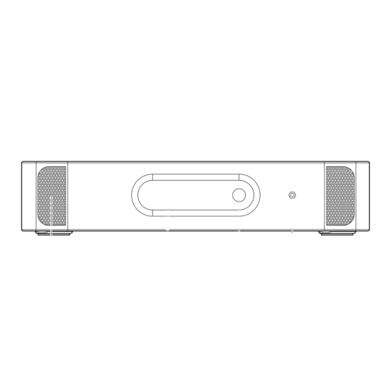
Page 84: Controls, Connectors And Indicators
Praesideo 3.5 | Installation and User Instructions | 3 | Control Equipment en | 84 Controls, connectors and 5.2.2 Rear view indicators The rear of the network controller (see figure 5.2) contains the following: 5.2.1 Front view 5 Ground - A connection to electrically ground the The front of the network controller (see figure 5.2) - Page 85 Praesideo 3.5 | Installation and User Instructions | 3 | Control Equipment en | 85 Caution Audio In 3 Audio Out 3 Audio In 4 Audio Out 4 Mains 115/230~ Risk of electric shock. Do not open. Avis Risk of electric shock.
-
Page 86: Internal View
Praesideo 3.5 | Installation and User Instructions | 3 | Control Equipment en | 86 5.2.3 Internal view The interior of the network controller (see figure 5.3) contains the following: 18 Ground jumper - A jumper that connects the signal ground to the safety ground. -
Page 87: Connections
Praesideo 3.5 | Installation and User Instructions | 3 | Control Equipment en | 87 Connections 5.3.1 Introduction Warning For safety reasons you must use an external This section gives an overview of typical system circuit breaker. Install in accordance with the connections using the network controller. - Page 88 Praesideo 3.5 | Installation and User Instructions | 3 | Control Equipment en | 88 5.3.4 Connecting the network 5.3.5.4 Via a network Connect the network controller to the Praesideo system If the configuration PC must be connected to the...
- Page 89 Praesideo 3.5 | Installation and User Instructions | 3 | Control Equipment en | 89 See figure 5.6 for details about the audio input sockets of the network controller. Audio Out Audio In figure 5.7: Audio output sockets figure 5.6: Audio input sockets table 5.4: Audio output socket details...
- Page 90 Praesideo 3.5 | Installation and User Instructions | 3 | Control Equipment en | 90 open (NO) depends on which action that has to take place when the control output is active (see table 5.5). Control In table 5.5: Control outputs details Connection Abbr.
-
Page 91: Installation
Praesideo 3.5 | Installation and User Instructions | 3 | Control Equipment en | 91 Installation 5.3.11 Compact flash card Praesideo stores digital audio messages on a type 1 The network controller is suitable for either table-top or compact flash card. Although flash cards up to 4 GB are 19-inch rack installation. -
Page 92: Using The Configuration Menu
Praesideo 3.5 | Installation and User Instructions | 3 | Control Equipment en | 92 Using the configuration menu 5.5.1 Overview A number of network controller settings are available via an interactive menu, using a 2x16 LCD display and a 'turn-and-push' menu button. The next figure gives an overview of the menu structure. - Page 93 Praesideo 3.5 | Installation and User Instructions | 3 | Control Equipment en | 93 5.5.2 Navigate through the menu To navigate through the status screens: Operating the menu is always a sequence of alternating 1 Turn the button to move through the status screens turns and pushes: (i.e.
- Page 94 Praesideo 3.5 | Installation and User Instructions | 3 | Control Equipment en | 94 4 Push the button to confirm: To jump back from a submenu to an item of the main menu: Date & Time 1 Turn the button to move the cursor to the main 2002/09/27 13:27 menu item number.
- Page 95 Praesideo 3.5 | Installation and User Instructions | 3 | Control Equipment en | 95 12 Turn to move the cursor to the second part of the IP 20 Push the button to confirm: address: 2Ba Address 192.168.000.015 2Ba Address 192.000.000.000...
-
Page 96: Configuration And Operation
Praesideo 3.5 | Installation and User Instructions | 3 | Control Equipment en | 96 Configuration and operation The menu items in the emergency menu provide additional information about the emergency state and 5.6.1 Introduction allow to acknowledge and reset the emergency state (see The next sections give descriptions of the possible table 5.8). - Page 97 Praesideo 3.5 | Installation and User Instructions | 3 | Control Equipment en | 97 The Faults ... menu screen itself shows the number of The faults and fault details displayed by the network active faults in the system. For example: controller are closely related to the faults that are displayed in the Logging Viewer (see chapter 57).
- Page 98 Praesideo 3.5 | Installation and User Instructions | 3 | Control Equipment en | 98 table 5. 1 1: Faults event table Fault Detail Logging message A/B fault (channel) Group A or B line fault Amp missing (channel) Amplifier missing...
- Page 99 Praesideo 3.5 | Installation and User Instructions | 3 | Control Equipment en | 99 table 5. 1 1: Faults event table Fault Detail Logging message Sec pwr RCS Backup power supply failure remote call station Supervision (channel) Pilot tone calibration...
- Page 100 Praesideo 3.5 | Installation and User Instructions | 3 | Control Equipment en | 100 5.6.7 Set monitoring options The Monitoring submenu is used to set which signal is sent to the monitoring loudspeaker or headphones. It can be one of the audio inputs, one of the audio outputs or no signal at all.
- Page 101 Praesideo 3.5 | Installation and User Instructions | 3 | Control Equipment en | 101 5.6.10 View MAC address The MAC Address menu item can be used to view the MAC address of the network controller. The MAC address is a unique address that is factory-set and cannot be changed.
-
Page 102: Technical Data
Praesideo 3.5 | Installation and User Instructions | 3 | Control Equipment en | 102 Technical Data 5.7.5 System bus Connector (rear side): 5.7.1 Physical characteristics Proprietary connector Dimensions (H x W x D): Preferred cable: 88 x 483 x 400 mm (19" installation, with brackets,... - Page 103 Praesideo 3.5 | Installation and User Instructions | 3 | Control Equipment en | 103 5.7.8 Audio line inputs 5.7.9 Audio microphone inputs (only input 1 and input 2) Connector (rear side): Connector (rear side): Female XLR and female stereo cinch socket per input.
- Page 104 Praesideo 3.5 | Installation and User Instructions | 3 | Control Equipment en | 104 5.7.10 Audio outputs 5.7.11 Control inputs Connector (rear side): Connector (rear side): One XLR and one stereo (dual mono) cinch for each Removable screw connector...
-
Page 105: Rs232 Interface
Praesideo 3.5 | Installation and User Instructions | 3 | Control Equipment en | 105 5.7.12 Control outputs 5.7.13 RS232 interface Connector (rear side): Connector (rear side): Removable screw connector Female 9 pole SUB-D connector Maximum cable length: Maximum cable length:... -
Page 106: Lbb4402/00 Audio Expander
Praesideo 3.5 | Installation and User Instructions | 3 | Control Equipment en | 106 LBB4402/00 Audio Expander 6. 1 Introduction The LBB4402/00 Audio Expander is used if the system requires additional audio inputs and outputs. See figure 6.1 for a block diagram of the audio expander. - Page 107 Praesideo 3.5 | Installation and User Instructions | 3 | Control Equipment en | 107 6.2.2 Rear view 6 Ground - A connection to electrically ground the The rear of the audio expander (see figure 6.2) contains audio expander. the following:...
-
Page 108: Connections
Praesideo 3.5 | Installation and User Instructions | 3 | Control Equipment en | 108 Connections 6.3.1 Introduction This section gives an overview of typical system Note The audio inputs can handle electret connections using the audio expander. microphones as well as dynamic microphones, •... - Page 109 Praesideo 3.5 | Installation and User Instructions | 3 | Control Equipment en | 109 See figure 6.4 for details about the audio output sockets. Control In Audio Out 10kΩ figure 6.4: Audio output sockets 10kΩ table 6.3: Audio output socket details...
-
Page 110: Installation
Praesideo 3.5 | Installation and User Instructions | 3 | Control Equipment en | 110 Installation 6.3.6 Connecting control outputs The audio expander has 5 control outputs. The control The audio expander is suitable for either table-top or outputs can be used to send signals to third party 19-inch rack installation. -
Page 111: Using The Configuration Menu
Praesideo 3.5 | Installation and User Instructions | 3 | Control Equipment en | 111 Using the configuration menu 6.5.1 Overview A number of audio expander settings are available via an interactive menu, using a 2x16 LCD display and a 'turn-and-push' menu button. - Page 112 Praesideo 3.5 | Installation and User Instructions | 3 | Control Equipment en | 112 6.5.2 Navigate through the menu To navigate through the status screens: Operating the menu is always a sequence of alternating 1 Turn the button to move through the status screens turns and pushes: (i.e.
- Page 113 Praesideo 3.5 | Installation and User Instructions | 3 | Control Equipment en | 113 4 Turn the button to the Monitoring option: To jump back from a sub-menu to an item of the main menu: 1 Monitoring 1 Turn the button to move the cursor to the main menu item number.
-
Page 114: Configuration And Operation
Praesideo 3.5 | Installation and User Instructions | 3 | Control Equipment en | 114 Configuration and operation 6.6.4 Fault status If there is an active fault, the Name screen also shows the 6.6.1 Introduction fault status (see table 6.6). If there is more than one The next sections give descriptions of the possible active fault, only the most severe fault is shown. - Page 115 Praesideo 3.5 | Installation and User Instructions | 3 | Control Equipment en | 115 6.6.6 Set monitoring options The Monitoring submenu is used to set which signal is sent to the monitoring headphones. It can be one of the audio inputs, one of the audio outputs or no signal at all.
-
Page 116: Technical Data
Praesideo 3.5 | Installation and User Instructions | 3 | Control Equipment en | 116 Technical data 6.7.5 System bus Connector (rear side): 6.7.1 Physical characteristics Proprietary connector Dimensions (H x W x D): Preferred cable: 88 x 483 x 400 mm (19" installation, with brackets,... - Page 117 Praesideo 3.5 | Installation and User Instructions | 3 | Control Equipment en | 117 6.7.7 Audio microphone inputs (only 6.7.8 Audio outputs input 1 and input 2) Connector (rear side): Connector (rear side): Female galvanically separated XLR per input...
- Page 118 Praesideo 3.5 | Installation and User Instructions | 3 | Control Equipment en | 118 6.7.9 Control inputs 6.7.10 Control outputs Connector (rear side): Connector (rear side): Removable screw connector Removable screw connector Total cable resistance: Maximum cable length: < 1 kohm (with line supervision) 1 km <...
-
Page 119: Lbb4404/00 Cobranet Interface
Praesideo 3.5 | Installation and User Instructions | 3 | Control Equipment en | 119 LBB4404/00 CobraNet CobraNet is a combination of software, hardware and network protocol which allows distribution of many Interface channels of real-time, high quality digital audio over an Ethernet network. -
Page 120: Controls And Connectors
Praesideo 3.5 | Installation and User Instructions | 3 | Control Equipment en | 120 Controls and connectors Connections 7.2.1 Front view 7.4.1 Introduction The front of the CobraNet interface (see figure 7.2) This section gives an overview of typical system contains the following: connections using the CobraNet interface. - Page 121 Praesideo 3.5 | Installation and User Instructions | 3 | Control Equipment en | 121 Network Control In Control Out C NC NO C NC NO C NC NO C NC NO C NC NO figure 7.2: Front and rear views of the CobraNet interface...
- Page 122 Praesideo 3.5 | Installation and User Instructions | 3 | Control Equipment en | 122 7.4.4 Connecting control inputs The CobraNet interface has 8 control inputs. The control inputs can receive signals from third party Note Do not combine control input wires of multiple equipment that must trigger actions in the Praesideo control inputs (e.g.
-
Page 123: Installation
Praesideo 3.5 | Installation and User Instructions | 3 | Control Equipment en | 123 Installation The CobraNet interface is suitable for either table-top or 19-inch rack installation. Four feet (for table-top use) and two brackets (for rack installation) are supplied. -
Page 124: Using The Configuration Menu
Praesideo 3.5 | Installation and User Instructions | 3 | Control Equipment en | 124 Using the configuration menu 7.7.1 Overview A number of CobraNet interface settings are available via an interactive menu, using a 2x16 LCD display and a ‘turn-and-push’ menu button. The next figure gives an overview of the menu structure. - Page 125 Praesideo 3.5 | Installation and User Instructions | 3 | Control Equipment en | 125 7.7.2 Navigate through the menu To navigate through the status screens: Operating the menu is always a sequence of alternating 1 Turn the button to move through the status screens turns and pushes: (i.e.
- Page 126 Praesideo 3.5 | Installation and User Instructions | 3 | Control Equipment en | 126 4 Turn the button to the Monitoring option: To jump back from a sub-menu to an item of the main menu: 1 Monitoring 1 Turn the button to move the cursor to the main menu item number.
-
Page 127: Configuration And Operation
Praesideo 3.5 | Installation and User Instructions | 3 | Control Equipment en | 127 Configuration and operation 7.8.4 Fault status If there is an active fault, the Name screen also shows the 7.8.1 Introduction fault status (see table 7.3). If there is more than one The next sections give descriptions of the possible active fault, only the most severe fault is shown. - Page 128 Praesideo 3.5 | Installation and User Instructions | 3 | Control Equipment en | 128 7.8.6 Set monitoring options The Monitoring submenu is used to set which signal is sent to the monitoring headphones. It can be one of the audio inputs, one of the audio outputs or no signal at all.
-
Page 129: Technical Data
Praesideo 3.5 | Installation and User Instructions | 3 | Control Equipment en | 129 Technical data 7.9.4 Mean time between failure MTBF: 7.9.1 Physical characteristics 50,000 hours at +55 °C Dimensions (H x W x D): (The MTBF doubles for every 10 °C decrease in 88 x 483 x 400 mm (19"... - Page 130 Praesideo 3.5 | Installation and User Instructions | 3 | Control Equipment en | 130 Intentionally left blank. Bosch Security Systems | 2011-02...
-
Page 131: Part 4 - Amplifiers
Praesideo 3.5 | Installation and User Instructions | 4 | Amplifiers en | 131 Part 4 - Amplifiers Bosch Security Systems | 2011-02... - Page 132 Praesideo 3.5 | Installation and User Instructions | 4 | Amplifiers en | 132 Intentionally left blank. Bosch Security Systems | 2011-02...
-
Page 133: Power Amplifiers
Praesideo 3.5 | Installation and User Instructions | 4 | Amplifiers en | 133 Power Amplifiers switched mode power supply. The amplifiers are protected against overload, overheat and short-circuits. See figure 8.1 for a block diagram of the power 8. 1 Introduction amplifier. -
Page 134: Controls, Connectors And Indicators
Praesideo 3.5 | Installation and User Instructions | 4 | Amplifiers en | 134 Controls, connectors and 8.2.2 Rear view indicators The rear of the power amplifier (see figure 8.2) contains the following: 8.2.1 Front view 4 Ground - A connection to electrically ground the The front of the power amplifier (see figure 8.2) contains... - Page 135 Praesideo 3.5 | Installation and User Instructions | 4 | Amplifiers en | 135 PRS-xPxxx, LBB4428/00 Power Amplifier PRS-1P500, PRS-2P250, PRS-4P125 Power Amplifier 14 13 Mains 115: 100-120V 50-60Hz T6.3A 250V 230: 220-240V 50-60Hz Audio In Control In T6.3A 250V...
-
Page 136: Connections
Praesideo 3.5 | Installation and User Instructions | 4 | Amplifiers en | 136 Connections 8.3.4 Ground connection LBB4428/00 only: A ground jumper can connect the 8.3.1 Introduction signal ground to the safety ground. This jumper is X3 on This section gives an overview of typical system the printed circuit board. - Page 137 Praesideo 3.5 | Installation and User Instructions | 4 | Amplifiers en | 137 8.3.5 Connecting the amplifier channels 8.3.5. 1 Introduction An amplifier channel (see figure 8.4) is a group of Caution To prevent the hazard of electric shocks, switch...
- Page 138 Praesideo 3.5 | Installation and User Instructions | 4 | Amplifiers en | 138 8.3.5.2 Loudspeaker lines Between the Lsp Out+ and Lsp Out- connections, the loudspeakers must be connected. The voltage between Caution Check the specifications of the loudspeakers to...
- Page 139 Praesideo 3.5 | Installation and User Instructions | 4 | Amplifiers en | 139 8.3.5.3 50 V output The 50 V output provided by the amplifier channel is table 8.5: Control outputs details actually a tap-off from the 50 V voltage for the...
- Page 140 Praesideo 3.5 | Installation and User Instructions | 4 | Amplifiers en | 140 Spare In + Main 100 V Lsp Out + Mains 115: 100-120V 50-60Hz T6.3A 250V 70 V 230: 220-240V 50-60Hz Control In Audio In T6.3A 250V...
- Page 141 Praesideo 3.5 | Installation and User Instructions | 4 | Amplifiers en | 141 8.3.6 Connecting audio inputs The number of audio inputs depends on the type of Spare In + power amplifier. 100 V Lsp Out + 70 V 50 V table 8.6: Number of audio inputs...
- Page 142 Praesideo 3.5 | Installation and User Instructions | 4 | Amplifiers en | 142 8.3.7 Connecting control inputs Each type of power amplifier has 8 control inputs. The control inputs can receive signals from third party Warning Do not connect DC or AC signals to the control...
- Page 143 Praesideo 3.5 | Installation and User Instructions | 4 | Amplifiers en | 143 8.3.8 Connecting back-up power Connect the back-up power supply to the back-up power connector on the back of the amplifier. Refer to Warning Never ground the positive terminal of the figure 8.13 and figure 8.14.
-
Page 144: Fan Control
Praesideo 3.5 | Installation and User Instructions | 4 | Amplifiers en | 144 Fan control • Full speed - The fans run at full speed continuously. The PRS-1P500, PRS-2P250 and PRS-4P125 amplifiers, Fan monitoring is activated. Do not enable Switch amplifiers to standby (see section 44.4) for this... -
Page 145: Installation
Praesideo 3.5 | Installation and User Instructions | 4 | Amplifiers en | 145 Installation The power amplifier is suitable for either table-top or 19-inch rack installation. Four feet (for table-top use) Caution When mounting the brackets to the unit, use the and two brackets (for rack installation) are supplied. -
Page 146: Using The Configuration Menu
Praesideo 3.5 | Installation and User Instructions | 4 | Amplifiers en | 146 Using the configuration menu 8.6.1 Overview A number of power amplifier settings are available via an interactive menu, using a 2x16 LCD display and a 'turn-and-push' menu button. The next figure gives an overview of the menu structure. - Page 147 Praesideo 3.5 | Installation and User Instructions | 4 | Amplifiers en | 147 8.6.2 Navigate through the menu To navigate through the status screens: Operating the menu is always a sequence of alternating 1 Turn the button to move through the status screens turns and pushes: (i.e.
- Page 148 Praesideo 3.5 | Installation and User Instructions | 4 | Amplifiers en | 148 5 Push the button to confirm: To jump back from a sub-menu to an item of the main menu: 1 Monitoring 1 Turn the button to move the cursor to the main menu item number.
-
Page 149: Configuration And Operation
Praesideo 3.5 | Installation and User Instructions | 4 | Amplifiers en | 149 Configuration and operation 8.7.3 Status screen The Status screen (see figure 8.18) shows the name of the 8.7.1 Introduction power amplifier and provides general information about The next sections give descriptions of the possible its (fault) status (see table 8.7). - Page 150 Praesideo 3.5 | Installation and User Instructions | 4 | Amplifiers en | 150 8.7.4 Main menu The Menu ... item provides access to the main menu. table 8.8: Main menus Menu item Description 1 Monitoring Go to the Monitoring submenu.
-
Page 151: Technical Data
Praesideo 3.5 | Installation and User Instructions | 4 | Amplifiers en | 151 Technical data 8.8.5 System bus Connector (rear side): 8.8.1 Physical characteristics Female proprietary connector Dimensions (H x W x D): Preferred cable: 88 x 483 x 400 mm (19" installation, with brackets,... - Page 152 Praesideo 3.5 | Installation and User Instructions | 4 | Amplifiers en | 152 8.8.8 Power consumption 8.8.8.2 Power consumption PRS-2P250 Load: 40 Ω / 125 nF per channel Stand-by/Power save: 5 W, 48 V(DC); 16 W, 120/230 V(AC) Note...
- Page 153 Praesideo 3.5 | Installation and User Instructions | 4 | Amplifiers en | 153 8.8.9 Audio line inputs 8.8.10 Audio microphone inputs Connector (rear side): Connector (rear side): 6 pole header (type ETB47-06-2-G1 (ECE)) for 6 pole header (type ETB47-06-2-G1 (ECE)) for...
- Page 154 Praesideo 3.5 | Installation and User Instructions | 4 | Amplifiers en | 154 8.8.11 Loudspeaker outputs and spare Power bandwidth: inputs 60 Hz - 19 kHz (-3 dB, distortion < 1%) at 50% of the Connector (rear side): rated output power...
- Page 155 Praesideo 3.5 | Installation and User Instructions | 4 | Amplifiers en | 155 8.8.12 Derating 8.8.13 Control inputs The graph shows the available continuous power used for emergency tones, speech, etc. as function of the Connector (rear side): ambient temperature.
- Page 156 Praesideo 3.5 | Installation and User Instructions | 4 | Amplifiers en | 156 8.8.14 Control outputs Connector (rear side): 1 x 9 pole header (type ETB 43-09-2-G1 (ECE)) with removable screw connector (shared with loudspeaker output and spare amplifier input)
-
Page 157: Prs-16Mci Multi Channel Interface
Praesideo 3.5 | Installation and User Instructions | 4 | Amplifiers en | 157 PRS-16MCI Multi Channel The multi channel interface gives supervision to the connected amplifier channels. Interface It can be used without connections to a basic amplifier. The multi channel interface then gives the Praesideo network 32 more control inputs and 16 more control 9. -
Page 158: Controls, Connections And Indicators
Praesideo 3.5 | Installation and User Instructions | 4 | Amplifiers en | 158 Controls, connections and 5 Control outputs - 16 Control outputs can be used indicators to send signals to trigger actions generated by the Praesideo network (see section 9.3.6). -
Page 159: Connectors
Praesideo 3.5 | Installation and User Instructions | 4 | Amplifiers en | 159 Connectors table 9. 1 Basic amplifier interface connections 9.3.1 Introduction Top row, indicated with Bottom row, indicated This section gives an overview of typical system triangle with circle connections using the multi channel interface. - Page 160 Praesideo 3.5 | Installation and User Instructions | 4 | Amplifiers en | 160 9.3.4 Connecting the multi channel amplifier, the multi channel interface can receive its interface by-pass power from the Praesideo system bus instead. A jumper sets the source of the power supply. The There are two methods to connect the bypass function location of the jumper is shown in figure 9.4.
- Page 161 Praesideo 3.5 | Installation and User Instructions | 4 | Amplifiers en | 161 Control In 9-16 17-24 25-32 10kΩ 10kΩ figure 9.6: Supervised control inputs 1 to 8 Control In 9-16 17-24 25-32 figure 9.7: Non-supervised control inputs 1 to 8...
-
Page 162: Installation
Praesideo 3.5 | Installation and User Instructions | 4 | Amplifiers en | 162 Installation 9.3.6 Connecting control outputs The multi channel interface has 16 control outputs. The The multi channel interface is suitable only for 19-inch control outputs can be used to send signals to third party rack installation. - Page 163 Praesideo 3.5 | Installation and User Instructions | 4 | Amplifiers en | 163 9.5.3 Multi channel interface and basic 9.5.4 Front panel LED indication amplifier co-operation The front panel of the multi channel interface has LED The multi channel interface monitors the functions of indicators that show the status of the connected the basic amplifier.
-
Page 164: Technical Data
Praesideo 3.5 | Installation and User Instructions | 4 | Amplifiers en | 164 Technical data 9.6.5 Power supply Multi channel interface power supply: 9.6.1 Physical characteristics Supplied by either: Dimensions (H x W x D): • the connected basic amplifier (default setting), or 88 x 483 x 400 mm (19"... - Page 165 Praesideo 3.5 | Installation and User Instructions | 4 | Amplifiers en | 165 9.6.8 Control outputs 9.6.9 Audio Bypass Maximum cable length: Connector audio in: 1 km XLR-female with locking Contact type: Input signal level: Relay contact, single pole, change-over contact...
-
Page 166: Basic Amplifiers
Praesideo 3.5 | Installation and User Instructions | 4 | Amplifiers en | 166 Basic Amplifiers The basic amplifier is completely supervised and fault events are reported via the multi channel interface to the Praesideo network controller. 10. 1 Introduction... -
Page 167: Controls, Connections And Indicators
Praesideo 3.5 | Installation and User Instructions | 4 | Amplifiers en | 167 10.2 Controls, connections and indicators 10.2.1 Front The front view of the basic amplifier (see figure 10.2) contains the following: 1 Mains status - Shows the status of the mains power connection and supply (see section 10.6). - Page 168 Praesideo 3.5 | Installation and User Instructions | 4 | Amplifiers en | 168 PRS-xBxxx Basic Amplifier PRS-1B500, PRS-2B250 Basic Amplifier Mains 115/230V 115: 100-120V 50-60Hz T6.3A H 250V 230: 220-240V 50-60Hz T6.3A H 250V Class 2 wiring Signal Ground...
-
Page 169: Connectors
Praesideo 3.5 | Installation and User Instructions | 4 | Amplifiers en | 169 10.3 Connectors The mains supply can be supervised by the basic amplifier (see figure 10.2, no. 9) and is available for the 10.3.1 Introduction multi channel interface. -
Page 170: Ground Connection
Praesideo 3.5 | Installation and User Instructions | 4 | Amplifiers en | 170 Proceed as follows: 1 Connect the triangle symbol connector of the MCI to the triangle symbol connector of the basic amplifier. Spare In Lsp Out Spare In... - Page 171 Praesideo 3.5 | Installation and User Instructions | 4 | Amplifiers en | 171 10.3.5.2 Loudspeaker lines Between the Lsp Out+ and Lsp Out- connections, the loudspeakers must be connected. The voltage between Caution Check the specifications of the loudspeakers to...
- Page 172 Praesideo 3.5 | Installation and User Instructions | 4 | Amplifiers en | 172 The loudspeaker lines can be connected in three This method has no redundancy. Both A and B relays different ways depending on the level of supervision are normally closed.
- Page 173 Praesideo 3.5 | Installation and User Instructions | 4 | Amplifiers en | 173 10.3.5.3 Spare amplifier channel A spare amplifier channel can be made available as a Channel 16 Spare input back-up channel for all channels of all basic amplifiers.
- Page 174 Praesideo 3.5 | Installation and User Instructions | 4 | Amplifiers en | 174 10.3.6 Connecting the local audio input The basic amplifiers have a local audio input per Channel 2 Channel 1 Unbalanced input Unbalanced input channel for a local signal source. This input has a low priority and is controlled by the multi channel interface.
-
Page 175: Fan Control
Praesideo 3.5 | Installation and User Instructions | 4 | Amplifiers en | 175 The back-up supply can be supervised by the basic amplifier (see figure 10.2, no. 9) and is available for the multi channel interface. Warning For safety reasons you must use an external circuit breaker. - Page 176 Praesideo 3.5 | Installation and User Instructions | 4 | Amplifiers en | 176 PRS-1B500 X652 PRS-2B250 X653 X652 PRS-4B125 3 2 1 3 2 1 PRS-8B060 figure 10. 1 6: Top view of the output boards for jumpers providing fan control...
-
Page 177: Installation
Praesideo 3.5 | Installation and User Instructions | 4 | Amplifiers en | 177 10.5 Installation 10.6 Operation The basic amplifier is suitable for only 19-inch rack The front panel of the amplifier has LED indicators that installation. show the status of the amplifier channels, battery back-up, mains supply and supervision. -
Page 178: Technical Data
Praesideo 3.5 | Installation and User Instructions | 4 | Amplifiers en | 178 10.7.4 Mean time between failure MTBF: Note 50,000 hours at +55 °C The first green LED is normally on when the pilot (The MTBF doubles for every 10 °C decrease in tone is enabled in the multi channel interface. - Page 179 Praesideo 3.5 | Installation and User Instructions | 4 | Amplifiers en | 179 10.7.8 Power consumption 10.7.8.3 Power consumption PRS-4B125 Load 80: Ω / 62 nF per channel Stand-by/Power save: 9 W, 48 V(DC); 16 W, 120/230 V(AC) Note...
- Page 180 Praesideo 3.5 | Installation and User Instructions | 4 | Amplifiers en | 180 10.7.9 Audio line inputs 10.7.10 Loudspeaker outputs and spare inputs Connector (rear side): 3 pole header for removable screw connector Connector (rear side): Preferred cable: 1 x 6 pole header with removable screw connector...
- Page 181 Praesideo 3.5 | Installation and User Instructions | 4 | Amplifiers en | 181 10.7.11 Derating Frequency response: The graph shows the continuous power used for PRS-1B500, PRS-2B250, PRS-4B125 emergency tones, speech, etc. as function of the ambient 60 Hz to 19 kHz (-3 dB) at -10 dB with maximum temperature.
-
Page 182: Single Loudspeaker Line Supervision
Praesideo 3.5 | Installation and User Instructions | 4 | Amplifiers en | 182 Single loudspeaker line supervision Note For the line supervision set to work correctly it is necessary to set the amplifiers to 70 V or 100 V 11. -
Page 183: Controls, Connectors And Indicators
Praesideo 3.5 | Installation and User Instructions | 4 | Amplifiers en | 183 11.2 Controls, connectors and loudspeaker line (see figure 11.3). Usually, the indicators supervision-slave is installed at the end of the loudspeaker line. 11.2.1 Supervision-master The supervision-master contains the following:... -
Page 184: Installation
Praesideo 3.5 | Installation and User Instructions | 4 | Amplifiers en | 184 11.3 Installation 11.3.1 Supervision-master Note In the spare amplifiers also single line supervision boards must be installed for those channels that have single line supervision Warning... - Page 185 Praesideo 3.5 | Installation and User Instructions | 4 | Amplifiers en | 185 PRS-1P500, PRS-2P250, PRS-4P125 LBB4428/00 Power Amplifier Power Amplifier figure 11.4: Supervision-master installation Bosch Security Systems | 2011-02...
- Page 186 Praesideo 3.5 | Installation and User Instructions | 4 | Amplifiers en | 186 11.3.2 Supervision-slave For a correct operation of the supervision, it is important that the loudspeaker line has the characteristics that are listed in section 11.5.5. Also, the...
-
Page 187: Technical Data Supervision-Master
Praesideo 3.5 | Installation and User Instructions | 4 | Amplifiers en | 187 11.4 Technical data The loudspeakers listed in table 11.2 have a provision supervision-master for a supervision-slave. 11.4.1 Physical characteristics table 11.2: Loudspeakers that have provision for a... -
Page 188: Technical Data Supervision-Slave
Praesideo 3.5 | Installation and User Instructions | 4 | Amplifiers en | 188 11.5 Technical data 11.5.5 Loudspeaker line characteristics supervision-slave Preferred cable: Single twisted pair, 0.75 mm to 1.5 mm . The use of 11.5.1 Physical characteristics multi-wire cables is not recommended. Cross talk of... -
Page 189: Multiple Loudspeaker Line Supervision
Praesideo 3.5 | Installation and User Instructions | 4 | Amplifiers en | 189 Multiple loudspeaker line The Power Amplifiers have one Supervision Control Board LBB4440/00 per channel. The addresses of the supervision connected EOL and loudspeaker supervision boards must be unique for that channel. -
Page 190: Controls, Connectors And Indicators
Praesideo 3.5 | Installation and User Instructions | 4 | Amplifiers en | 190 12.2 Controls, connectors and 12.2.2 Loudspeaker supervision board indicators The loudspeaker supervision board LBB4441/00(see figure 12.2) contains the following: 12.2.1 Supervision control board Flying leads - Two flying leads (30 cm) with... -
Page 191: Installation
Praesideo 3.5 | Installation and User Instructions | 4 | Amplifiers en | 191 12.3 Installation 12.2.3 EOL supervision board The EOL supervision board LBB4443/00(see figure 12.3.1 Supervision control board 12.3) contains the following: Flying leads - Two flying leads (30 cm) with... - Page 192 Praesideo 3.5 | Installation and User Instructions | 4 | Amplifiers en | 192 12.3.2 Loudspeaker supervision board PRS-1P500, PRS-2P250, PRS-4P125 Power Amplifier Warning To prevent the hazard of electric shocks, switch the power amplifier and the back-up power supplies off, before starting installing the loudspeaker supervision board.
- Page 193 Praesideo 3.5 | Installation and User Instructions | 4 | Amplifiers en | 193 For a correct operation of the supervision, it is table 12. 1 : Loudspeakers that have a provision for important that the loudspeaker line has the characteristics that are listed in section 12.6.5.
-
Page 194: Addressing
Praesideo 3.5 | Installation and User Instructions | 4 | Amplifiers en | 194 Lsp Out Lsp Out + figure 12.6: Loudspeaker supervision connection 3. 1 12.3.3 EOL supervision board The procedure for installing an EOL supervision board is similar to the installation of a loudspeaker supervision board (see section 12.3.2). -
Page 195: Technical Data Supervision Control Board
Praesideo 3.5 | Installation and User Instructions | 4 | Amplifiers en | 195 12.5 Technical data supervision For example, the ID selectors in figure 12.8 show control board address 2C. 12.5.1 Physical characteristics Dimensions (H x W x D):... -
Page 196: Technical Data Loudspeaker Supervision Board
Praesideo 3.5 | Installation and User Instructions | 4 | Amplifiers en | 196 12.6 Technical data loudspeaker 12.6.5 Loudspeaker line characteristics supervision board Preferred cable: Single twisted pair, 0.75 mm to 1.5 mm . The use of 12.6.1 Physical characteristics multiwire cables is not recommended. -
Page 197: Technical Data Eol Supervision Board
Praesideo 3.5 | Installation and User Instructions | 4 | Amplifiers en | 197 12.7 Technical data EOL supervision board The technical data of the EOL supervision board are the same as the technical data of the loudspeaker supervision board (see section 12.6). -
Page 198: Lbb4446/00 Brackets
Praesideo 3.5 | Installation and User Instructions | 4 | Amplifiers en | 198 LBB4446/00 Brackets The LBB4446/00 Brackets (see figure 13.1) are used to install supervision slave PCBs in junction boxes or in loudspeaker housings. Each set contains 10 pieces of aluminium brackets including screws and washers. -
Page 199: Lbc1256/00 Evac Connection Adapter
Praesideo 3.5 | Installation and User Instructions | 4 | Amplifiers en | 199 LBC1256/00 EVAC The EVAC connection block itself is a three pole screw connector to which the loudspeaker can be connected Connection Adapter (see figure 14.2). Lsp - Lsp + 14. - Page 200 Praesideo 3.5 | Installation and User Instructions | 4 | Amplifiers en | 200 Intentionally left blank. Bosch Security Systems | 2011-02...
-
Page 201: Part 5 - Call Stations
2011-02 | Installation and User Instructions | 5 | Call Stations en | 201 Part 5 - Call Stations Bosch Security Systems | 2011-02... - Page 202 2011-02 | Installation and User Instructions | 5 | Call Stations en | 202 Intentionally left blank. Bosch Security Systems | 2011-02...
-
Page 203: Lbb4430/00 Call Station Basic
See figure 15.1 for a block diagram of the call station basic. Headset Keypad Keypad (max. 16) Microphone Network Processor Power/Fault Call Status System Status Network Redundancy Switching figure 15. 1 : Block diagram Bosch Security Systems | 2011-02... -
Page 204: Controls, Connectors And Indicators
(see section 15.3.2). 7 Interface connector - A flat cable connector to connect the call station basic to a keypad. figure 15.2: Headset connector Note The wire of the headset may not be longer than 3 meter. Bosch Security Systems | 2011-02... - Page 205 2011-02 | Installation and User Instructions | 5 | Call Stations en | 205 figure 15.3: Front and rear views figure 15.4: Bottom view Bosch Security Systems | 2011-02...
-
Page 206: Installation
(if fitted). An emergency announcement is being made. Bosch Security Systems | 2011-02... -
Page 207: Technical Data
32 ohm Signal/Noise ratio earphone: 80 dB at max. output (tolerance ± 3 dB) Cross-talk (earphone to microphone): < 40 dB at -42 dBV/Pa and 1 kHz (tolerance ± 3 dB) Output power: 1 mW Bosch Security Systems | 2011-02... -
Page 208: Lbb4432/00 Call Station Keypad
(see chapter 47). To protect keys from Control being pushed accidentally (e.g. alarm or emergency keys), key covers (LBB4436/00) can be put on them. figure 16. 1 : Block diagram figure 16.2: Top view Bosch Security Systems | 2011-02... -
Page 209: Configuration
The first keypad for pre-configured actions has ID 0, the next 1, and so on up to F for the sixteenth keypad for pre-configured actions. figure 16.4: ID selector figure 16.3: Bottom view Bosch Security Systems | 2011-02... -
Page 210: Installation
3 Slide the connecting plate into the bottom of the keypad. 4 Fasten the connection plate using three screws. 5 Put the lid back by sliding it to the right and snapping it into the keypad. figure 16.5: Installation Bosch Security Systems | 2011-02... -
Page 211: Operation
Dimensions (H x W x D): No fault reporting when >20V 70 x 95 x 200 mm Network power consumption: Weight: 1.3 W 0.3 kg Max. flat cable length: 5 m (for all keypads together) Bosch Security Systems | 2011-02... -
Page 212: Prs-Csnkp Numeric Keypad
4 Keypad connector - A connector to connect the Control numeric keypad to the previous keypad or to the (remote) call station (see section 17.5). 5 Contrast control - Adjusts the contrast of the LCD. figure 17. 1 : Block diagram Bosch Security Systems | 2011-02... -
Page 213: Installation
3 Slide the connecting plate into the bottom of the keypad. 4 Fasten the connection plate using three screws. 5 Put the lid back by sliding it to the right and snapping it into the keypad. figure 17.4: Installation Bosch Security Systems | 2011-02... -
Page 214: Operation
(< 1 s) entered zone priority, the zone (group) is shown between Long press Delete all entered zones parenthesis. (> 2 s) Short press Enter (< 1 s) Long press Lock call station (> 2 s) Bosch Security Systems | 2011-02... -
Page 215: Technical Data
100,000 hours at +45 °C (The MTBF doubles for every 10 °C decrease in temperature.) 17.7.5 System bus Power supply via network: 18 to 56V (DC) No fault reporting when >20V Network power consumption: 1.6 W Bosch Security Systems | 2011-02... -
Page 216: Lbb4433/00 Call Station Kit
Headset Keypad Keypad (max. 16) Microphone Network Processor Power/Fault (2) Call Status Control Inputs System Status (2) Network Redundancy Switching figure 18. 1 : Block diagram Bosch Security Systems | 2011-02... -
Page 217: Controls, Connectors And Indicators
Control input/outputs - The control input and five control outputs are used as replacement for the PTT key and LEDs on the LBB4430/00 Call Station Basic (see section 18.2.4). X142 X143 figure 18.2: Component side Bosch Security Systems | 2011-02... - Page 218 Do not connect DC or AC signals to the control > 27 kohm inputs, otherwise the input circuit may be Resistance detection (supervision disabled): damaged. Only use voltage-free contacts. Contact closed < 12 kohm Contact open > 17.5 kohm Bosch Security Systems | 2011-02...
- Page 219 Volume control voltage: Volume Headset 0 to 3.3 V Earphone figure 18.5: Headset connection diagram Note The linear resistor R (typical value: 10 kohm) is used to create a control voltage from the supply voltage. Bosch Security Systems | 2011-02...
- Page 220 (-3 dB with respect to level at 1 kHz) Mic+ --- not connected --- PTT input contact 10kΩ blue 10kΩ black white black (thick) figure 18.6: LBB9081 connection diagram white black figure 18.7: LBB9082 connection diagram Bosch Security Systems | 2011-02...
- Page 221 Output 5, in (system emergency indicator) max. 30 mA (in total max. 3 LEDs are simultaneously on) Output type: open collector/drain Output voltage: max. 56 V (per pin) Output sink current: max. 100 mA per output switch pin Bosch Security Systems | 2011-02...
- Page 222 R1 = 180 Ω, R2 = 150 Ω (HW07/00 to HW07/03) = Fault Indicator R1 = 330 Ω, R2 = 0 Ω (before HW07/00) = Call Indicator = System Priority Indicator = System Emergency Indicator figure 18.9: Internally powered LED Bosch Security Systems | 2011-02...
- Page 223 4, 5, 6 Speaker - table 18. 1 0: X142 technical data Impedance: 8 to 32 ohm Signal/Noise ratio: typical 80 dB ± 3 dB at max. output Output power: typical 100 mW, max. 300 mW Bosch Security Systems | 2011-02...
-
Page 224: Installation
Note If the call station kit is installed in a vibrating surrounding (e.g. a ship), glue the pin header to the PCB. figure 18. 1 3: Tyco AMP 1-141708-1 shrink-contact Bosch Security Systems | 2011-02... -
Page 225: Technical Data
50,000 hours at +55 °C (The MTBF doubles for every 10 °C decrease in temperature.) 18.4.5 System bus Power supply via network: 18 to 56V (DC) No fault reporting when >20V Network power consumption: 6.2 W (excluding keypads) Bosch Security Systems | 2011-02... -
Page 226: Lbb4434/00 Call Station Keypad Kit
(e.g. for emergency call stations). See figure 19.1 for a block diagram of the call station keypad kit. call station or next keypad previous keypad Control figure 19. 1 : Block diagram Bosch Security Systems | 2011-02... -
Page 227: Controls, Connectors And Indicators
Disconnect the system cable from the call station (kit) and back-up supplies before you are going to connect a keypad to it. Connecting a keypad to a powered (remote) call station can damage the (remote) call station. Bosch Security Systems | 2011-02... - Page 228 Output 7, out (yellow) Current (control inputs): Output 7, in (yellow) max. 0.5 mA Output 8, out (yellow) Voltage (control inputs): Output 8, in (yellow) max. 3.3 V with internal pull-up resistor of 10 kΩ Bosch Security Systems | 2011-02...
- Page 229 LEDs, then the maximum total load for all control outputs together should be figure 19.5: Externally powered LED <64 mA. I < 100 mA Max. 30V Output X, figure 19.6: Externally powered relay Bosch Security Systems | 2011-02...
- Page 230 The first keypad for pre-configured actions has ID 0, the next 1, and so on up to F for the sixteenth keypad for pre-configured Clock I2C (SCL) actions. Power Power Power Power figure 19.7: ID selector Bosch Security Systems | 2011-02...
-
Page 231: Installation
Note If the call station keypad kit is installed in a vibrating surrounding (e.g. a ship), glue the pin header to the PCB. figure 19.9: Tyco AMP 1-141708-1 shrink-contact Bosch Security Systems | 2011-02... -
Page 232: Technical Data
50,000 hours at +55 °C (The MTBF doubles for every 10 °C decrease in temperature.) 19.4.5 System bus Power supply via network: 18 to 56V (DC) No fault reporting when >20V Network power consumption: 1.2 W Bosch Security Systems | 2011-02... -
Page 233: Prs-Csr Remote Call Station
LBB4437/00 to connect LBB4438/00 and LBB4439/00 remote call stations to the system. Headset External Keypad Keypad Power (max. 16) Microphone Processor Power/Fault Call Status Control Inputs System Status Cat-5 Network Interface figure 20. 1 : Block diagram Bosch Security Systems | 2011-02... -
Page 234: Controls, Connectors And Indicators
PRS-CSI only. 8 Service connector - A connector used for manufacturing. Not for normal use. 9 Interface connector - A flat cable connector to connect the remote call station to a call station keypad. Bosch Security Systems | 2011-02... - Page 235 (see figure 20.5): figure 20.5: Connection diagram (external view) table 20. 1 : Kycon KPP-4P connector details Signal figure 20.4: Bottom view Ground External supply Control input 1 Control input 2 Bosch Security Systems | 2011-02...
- Page 236 3 meter. It is also possible to supervise the cables for short-circuits and open connections (see figure 20.6 and figure 20.7). Whether a control input is actually supervised or not is defined in the configuration. Bosch Security Systems | 2011-02...
-
Page 237: Installation
(if fitted). An emergency announcement is being made. Normal announcements can be made to the zones which are not involved. Bosch Security Systems | 2011-02... -
Page 238: Technical Data
80 dB at max. output 20.6.4 Mean time between failure Sound pressure level: MTBF: 85 dB(SPL) at 0.5 m and 1 kHz 50,000 hours at +45 °C (The MTBF doubles for every 10 °C decrease in temperature.) Bosch Security Systems | 2011-02... - Page 239 17.5 kohm to 22 kohm Cable broken > 27 kohm Resistance detection (supervision disabled): Contact closed < 12 kohm Contact open > 17.5 kohm External contacts: Voltage-free closing or breaking contacts (relay contacts, mechanical switches, mercury contacts etc.) Bosch Security Systems | 2011-02...
-
Page 240: Prs-Csrk Remote Call Station Kit
LBB4438/00 and LBB4439/00 remote call stations to the system. Headset External Keypad Keypad Power (max. 16) Microphone Network Processor Power/Fault Call Status Control Inputs System Status Cat-5 Network Interface figure 21. 1 : Block diagram Bosch Security Systems | 2011-02... -
Page 241: Controls, Connectors And Indicators
PRS-CSR Remote Call Station (see section Keypad interface - The keypad interface is 21.2.4). used to connect up to 16 keypads to the remote call station kit (see section 21.2.6). X107 X501 X511 X908 X301 X300 figure 21.2: Component side Bosch Security Systems | 2011-02... - Page 242 Do not connect DC or AC signals to the control > 27 kohm inputs, otherwise the input circuit may be Resistance detection (supervision disabled): damaged. Only use voltage-free contacts. Contact closed < 12 kohm Contact open > 17.5 kohm Bosch Security Systems | 2011-02...
- Page 243 If a volume control is not needed, pin 3 and 4 Mic+ must be connected to each other. The volume --- not connected --- level of the earphone is then at its maximum. PTT input contact Bosch Security Systems | 2011-02...
- Page 244 Input control range: -7 to 8 dB S/N: min. 60 dB at default sensitivity Headroom: min. 30 dB at default sensitivity Bandwidth: 340 to 14000 Hz (-3 dB with respect to level at 1 kHz) Bosch Security Systems | 2011-02...
- Page 245 10 mA (per pin) max. 30 mA (in total max. 3 LEDs are simultaneously on) Output type: open collector/drain Output voltage: max. 56 V (per pin) Output sink current: max. 100 mA per output switch pin Bosch Security Systems | 2011-02...
- Page 246 21. 1 1: Externally powered relay +5V, 30 mA R = 330 Ω = Power Indicator = Fault Indicator = Call Indicator = System Priority Indicator = System Emergency Indicator figure 21.9: Externally powered LED Bosch Security Systems | 2011-02...
- Page 247 The second keypad is connected to the first, the third to the second etc. using standard flat cables. table 21. 1 1: X1 connector details Signal Synchronization line. Interrupt line (INT) Data I2C (SDA) Clock I2C (SCL) Power Power Power Power Bosch Security Systems | 2011-02...
-
Page 248: Installation
Note If the remote call station kit is installed in a vibrating surrounding (e.g. a ship), glue the pin header to the PCB. figure 21. 1 3: Tyco AMP 1-141708-1 shrink-contact Bosch Security Systems | 2011-02... -
Page 249: Technical Data
(The MTBF doubles for every 10 °C decrease in temperature.) 21.4.5 External power supply Connector: Kycon KPJ-4S Input voltage range: 18 to 56V (DC) No fault reporting when >20V Power consumption: 4 W at 48 V (excluding keypads) Bosch Security Systems | 2011-02... -
Page 250: Prs-Csi Call Station Interface
(old) LBB4438/00 and LBB4439/00 remote call stations. Fault Power Control Inputs Cat.5 Network Processor Interface External (back-up) Power Power 18 - 56 V Supply Network Redundancy Switching figure 22. 1 : Block diagram Bosch Security Systems | 2011-02... -
Page 251: Controls, Connectors And Indicators
8 Service connector - A connector used for manufacturing. Not for normal use. Caution Do not connect the connections 6 and 8 to any Telecom or Ethernet network. These connections are dedicated for PRS-CSR or PRS-CSRK and service equipment. figure 22.2: Exterior Bosch Security Systems | 2011-02... -
Page 252: Connections
(refer to section 22.3.3). 18-56 V(DC), optional table 22. 1 : Jumper settings Power supply Powerlink setting Network Concept I Ground Concept II Network Concept III figure 22.5: Connecting the network and call stations Bosch Security Systems | 2011-02... - Page 253 The remote call station and the call station interface are Other types of power supply are not tested with delivered with a separate Kycon KPP4-P connector to Praesideo and may cause harm. connect external power supplies. Bosch Security Systems | 2011-02...
-
Page 254: Installation
10kΩ 10kΩ figure 22.7: Supervised control input Control input figure 22.8: Non-supervised control input figure 22.9: Installation Mounting of this bracket and the unit on a drywall sheet construction requires screws with a minimum screw Bosch Security Systems | 2011-02... -
Page 255: Operation
3.7 W at 48 V (excluding keypads) 22.6.6 External power supply Connector: Kycon KPP4-P Input voltage range: 18 to 56V (DC) No fault reporting when >20V Power consumption: 3.7 W at 48 V (excluding keypads) Bosch Security Systems | 2011-02... - Page 256 2011-02 | Installation and User Instructions | 5 | Call Stations en | 256 22.6.7 Call station interface Connector: RJ45 Cable type: Cat-5 (4x twisted pair, straight) Maximum cable length: 1000 m Bosch Security Systems | 2011-02...
-
Page 257: Prs-Crf Call Stacker
Units can be connected to the Praesideo network at any place. Fault Power Network Processor Message Manager Message Recorder Message Player (8x) (8x) Network Redundancy Switching figure 23. 1 : Block diagram Bosch Security Systems | 2011-02... -
Page 258: Controls And Indicators
Mounting of this bracket and the unit on a drywall sheet construction requires screws with a minimum screw length of 22 mm (7/8") and a minimum diameter of 2.5 mm (3/32"). Mounting was evaluated for use on a drywall surface only. figure 23.2: Exterior Bosch Security Systems | 2011-02... -
Page 259: Operation
> 85 dB 600 to 1100 hPa Crosstalk: < -85 dB 23.6.3 EMC and Safety Electromagnetic compatibility: EN55103-1/FCC-47 part 15B EN55103-2 EN50121-4 EN50130-4 Electrical safety: IEC60065 (CB-scheme) EN60065 Approvals: CE marking EN60849, EN54-16 and ISO7240-16 IEC60945 Bosch Security Systems | 2011-02... -
Page 260: Lbb4436/00 Key Covers
Station Keypad using a pair of pliers. 3 Snap the key cover and replacement lens assembly in the LBB4432/00 Call Station Keypad. 4 Optionally, use cyano acrylate glue to fix the LBB4436/00 Key Cover permanently to the LBB4432/00 Call Station Keypad. Bosch Security Systems | 2011-02... -
Page 261: Part 6 - Installation Accessories
Praesideo 3.5 | Installation and User Instructions | 6 | Installation Accessories en | 261 Part 6 - Installation Accessories Bosch Security Systems | 2011-02... - Page 262 Praesideo 3.5 | Installation and User Instructions | 6 | Installation Accessories en | 262 Intentionally left blank. Bosch Security Systems | 2011-02...
-
Page 263: Prs-Nsp Network Splitter
Praesideo 3.5 | Installation and User Instructions | 6 | Installation Accessories en | 263 PRS-NSP Network 25.2 Controls and connectors Splitter 25.2.1 Exterior The exterior of the network splitter (see figure 25.2) contains the following: 25. 1 Introduction 1 External power supply - A connection for an The PRS-NSP Network Splitter is used to create (optional) external power supply. - Page 264 Praesideo 3.5 | Installation and User Instructions | 6 | Installation Accessories en | 264 figure 25.3: Interior of the network splitter figure 25.2: Exterior of the network splitter Bosch Security Systems | 2011-02...
- Page 265 Praesideo 3.5 | Installation and User Instructions | 6 | Installation Accessories en | 265 25.2.2 Interior The interior of the network splitter (see figure 25.3 and figure 25.4) contains the following: Note The numbering in figure 25.4 differs from the numbering in figure 25.2 and figure 25.3.
-
Page 266: Connections
Praesideo 3.5 | Installation and User Instructions | 6 | Installation Accessories en | 266 25.3 Connections 25.3.3 Connecting a power supply This unit is powered by the network controller, via the 25.3.1 Introduction Praesideo system bus. But the network splitter is... -
Page 267: Installation
Praesideo 3.5 | Installation and User Instructions | 6 | Installation Accessories en | 267 25.4 Installation The network splitter can be attached to a wall or any Note other flat surface using a bracket (see figure 25.7). The The pin numbers are also indicated on the inside distance (d) between the holes in the bracket is 40 mm. -
Page 268: Technical Data
Praesideo 3.5 | Installation and User Instructions | 6 | Installation Accessories en | 268 25.6 Technical data 25.6.5 System bus Number of connections: 25.6.1 Physical characteristics 4x proprietary female connectors Dimensions (H x W x D): Position: 27 x 243 x 80 mm (without bracket) -
Page 269: Prs-Fin, Prs-Finna, Prs-Fins Fiber Interface
Praesideo 3.5 | Installation and User Instructions | 6 | Installation Accessories en | 269 PRS-FIN, PRS-FINNA, In emergency sound systems, do not use this type of fiber interface to power far-end units. Since it does not PRS-FINS Fiber Interface have any control inputs, it is not possible to supervise its external power supply (if connected). - Page 270 Praesideo 3.5 | Installation and User Instructions | 6 | Installation Accessories en | 270 PRS-FIN, PRS-FINS PRS-FINNA figure 26.2: Exterior of the fiber interface Bosch Security Systems | 2011-02...
-
Page 271: Connections
Praesideo 3.5 | Installation and User Instructions | 6 | Installation Accessories en | 271 26.3 Connections The GOF connector (see figure 26.4) is an SC connector, which uses invisible infra-red light 26.3.1 Introduction (1300 nm). This section gives an overview of typical system connections using the fiber interface: •... - Page 272 Praesideo 3.5 | Installation and User Instructions | 6 | Installation Accessories en | 272 table 26.2: Kycon KPP-4P connector details Signal Ground Power from external power supply to the PRS-FINxx (max. 48 V / 5 A) Output power from the system bus (max.
- Page 273 Praesideo 3.5 | Installation and User Instructions | 6 | Installation Accessories en | 273 26.3.4 Connecting control inputs It is also possible to have the cables supervised for The fiber interface has two control inputs (see short-circuits and open connections (see figure 26.8 and figure 26.7).
-
Page 274: Installation
Praesideo 3.5 | Installation and User Instructions | 6 | Installation Accessories en | 274 26.4 Installation 26.3.5Operation The two LEDs on the fiber interface provide The fiber interface can be attached to a wall or any information about the status of the fiber interface. -
Page 275: Technical Data
Praesideo 3.5 | Installation and User Instructions | 6 | Installation Accessories en | 275 26.5 Technical data 26.5.5 System bus Number of connections: 26.5.1 Physical characteristics 1x proprietary female connector (POF) Dimensions (H x W x D): 1x industry standard SC connector (GOF) -
Page 276: Lbb4416/Xx Network Cables
Praesideo 3.5 | Installation and User Instructions | 6 | Installation Accessories en | 276 LBB4416/xx Network 27.2 Connectors Except for LBB4416/00, all cables are terminated with Cables male, proprietary connectors on both ends of the cable. See figure 27.3 for connector details. -
Page 277: Wiring
Praesideo 3.5 | Installation and User Instructions | 6 | Installation Accessories en | 277 27.3 Wiring 27.5 Technical data See figure 27.4 for details about the wires inside the extension cables. Insulation: LSZH (low smoke/zero halogen), black Outer diameter:... -
Page 278: Lbb4417/00 Network Connectors
Praesideo 3.5 | Installation and User Instructions | 6 | Installation Accessories en | 278 LBB4417/00 Network Connectors The LBB4417/00 Network Connectors are used to create custom-made cables in combination with LBB4416/00 Network Cable (100 m) and the LBB4418/00 Cable-connector Tool Kit. -
Page 279: Lbb4418 Cable-Connector Tool Kit
Praesideo 3.5 | Installation and User Instructions | 6 | Installation Accessories en | 279 LBB4418 Cable-connector 29.2 Toolkit contents Tool Kit 29. 1 Introduction The LBB4418/00 Cable-connector Toolkit is intended for creating optical network cables (see figure 29.1) out of LBB4416/00 Network Cable (100 m) and LBB4417/ 00 Network Connectors. - Page 280 Praesideo 3.5 | Installation and User Instructions | 6 | Installation Accessories en | 280 Toolkit supplier: • Rennsteig Werkzeuge GmbH Viernau, Thüringen, Germany Supplier type number: 600 100 PHI Note Before using the POF cutter/stripping tool (tool 6), release its blocking screw using the Torx screwdriver (tool 7).
-
Page 281: Connector Components
Praesideo 3.5 | Installation and User Instructions | 6 | Installation Accessories en | 281 29.3 Connector components Each optical network connector (LBB4417/00) consists of 10 components (see figure 29.3 and figure 29.4). figure 29.3: Connector assembly drawing table 29.2: Connector components... -
Page 282: Cable-Connector Installation
Praesideo 3.5 | Installation and User Instructions | 6 | Installation Accessories en | 282 29.4 Cable-connector installation 29.4.3 Preparation Proceed as follows: 29.4.1 Introduction 1 Cut the optical network cable to the required length This chapter contains a step-by-step description of the using the cable cutter (tool 2). - Page 283 Praesideo 3.5 | Installation and User Instructions | 6 | Installation Accessories en | 283 29.4.4 Crimping bush 7 Crimp the bush on the outer sheath using the Proceed as follows: crimping tool (tool 3, see figure 29.9). The crimping...
- Page 284 Praesideo 3.5 | Installation and User Instructions | 6 | Installation Accessories en | 284 29.4.6 Installing socket contacts 9 Strip the red and brown insulations from the copper wires by pushing them to the mechanical stop of the Proceed as follows: stripping tool (tool 5, see figure 29.11).
- Page 285 Praesideo 3.5 | Installation and User Instructions | 6 | Installation Accessories en | 285 29.4.7 Stripping fibers 11 Slide one of the stripped, copper wires into the contact area of the socket contact and close the Proceed as follows:...
- Page 286 Praesideo 3.5 | Installation and User Instructions | 6 | Installation Accessories en | 286 14 Close the tool to fix the cable and pull the ‘trigger’ to 17 Close the tool and pull the fiber out to strip the cut the fiber (see figure 29.18).
- Page 287 Praesideo 3.5 | Installation and User Instructions | 6 | Installation Accessories en | 287 29.4.8 Installing the ferrules 21 Insert a plastic optical fiber into the ferrule in the Proceed as follows: spring-loaded stop of the POF positioning tool (see 19 Insert a ferrule into the spring-loaded stop of the figure 29.23).
- Page 288 Praesideo 3.5 | Installation and User Instructions | 6 | Installation Accessories en | 288 29.4.9 Assembling the connector 25 Crimp the ferrules on the sheath using the crimping tool (tool 3, see figure 29.25). See figure 29.26 for the...
- Page 289 Praesideo 3.5 | Installation and User Instructions | 6 | Installation Accessories en | 289 = Red = Brown figure 29.29: Wiring diagram applied to type A optical network cables = Red = Brown figure 29.30: Wiring diagram applied to type B optical network cables...
- Page 290 Praesideo 3.5 | Installation and User Instructions | 6 | Installation Accessories en | 290 Where applicable, the way in which the connectors 28 Put the socket contacts in the mounting block (see must be assembled on both sides of the cables is shown figure 29.33).
- Page 291 Praesideo 3.5 | Installation and User Instructions | 6 | Installation Accessories en | 291 30 Click the front housing on the mounting block/back 32 Tighten the Torx screw using the Torx screwdriver housing assembly (see figure 29.35). (tool 7, see figure 29.37) figure 29.35: Installing the front housing...
-
Page 292: Lbb4419/00 Cable Couplers
Praesideo 3.5 | Installation and User Instructions | 6 | Installation Accessories en | 292 LBB4419/00 Cable Couplers The LBB4419/00 Cable Couplers are used to connect extension cables to each other. However, in each cable coupler, a small a amount of light gets lost. Therefore,... -
Page 293: Part 7 - System Hardware Installation
Praesideo 3.5 | Installation and User Instructions | 7 | System Hardware Installation en | 293 Part 7 - System Hardware Installation Bosch Security Systems | 2011-02... - Page 294 Praesideo 3.5 | Installation and User Instructions | 7 | System Hardware Installation en | 294 Intentionally left blank. Bosch Security Systems | 2011-02...
-
Page 295: Cabling
Praesideo 3.5 | Installation and User Instructions | 7 | System Hardware Installation en | 295 Cabling 31.2 System bus A system bus cable (see figure 31.2) has two plastic optical fiber (POF) ‘wires’ and two copper wires. The 31. 1... -
Page 296: Dust Caps
Praesideo 3.5 | Installation and User Instructions | 7 | System Hardware Installation en | 296 31.4 Maximum distance Due to light loss, the maximum length of POF cabling Note (and therefore also system bus cables) between two During both installation and operation, the pieces of equipment is 50 m. -
Page 297: Maximum Cable Length
Praesideo 3.5 | Installation and User Instructions | 7 | System Hardware Installation en | 297 31.5 Maximum cable length The graph (see figure 31.5) shows the relation between The maximum length of all optical fibers together (both the number of nodes in the system and maximum optical fiber length in the system. -
Page 298: Bending And Coiling
Praesideo 3.5 | Installation and User Instructions | 7 | System Hardware Installation en | 298 31.6 Bending and coiling 31.6.3 Coiling The minimum coiling radius is 110 mm (see figure 31.8) 31.6.1 Introduction The POF cable may be bend or coiled. However, the R=110 mm rules in this chapter must be observed. -
Page 299: Architecture
Praesideo 3.5 | Installation and User Instructions | 7 | System Hardware Installation en | 299 Architecture 32.3 Redundant cabling The basic system has no redundant cabling. If the cable between the call station basic and the power amplifier 32. 1... -
Page 300: Tap-Offs
Praesideo 3.5 | Installation and User Instructions | 7 | System Hardware Installation en | 300 32.4 Tap-offs 32.5 Spare amplifiers The network splitter makes it possible to create tap-offs Besides using redundant cabling it is also possible to add (see figure 32.3). -
Page 301: Cobranet
Praesideo 3.5 | Installation and User Instructions | 7 | System Hardware Installation en | 301 32.6 CobraNet Because of delay variations, it is not allowed to connect CobraNet is a standard for transporting multiple digital more than 7 switches in series. -
Page 302: Failsafe
Praesideo 3.5 | Installation and User Instructions | 7 | System Hardware Installation en | 302 32.7 Failsafe control system disturbs the operation of the line supervision. The line supervision set uses the 32.7.1 Introduction loudspeaker line. Any volume control in the line... - Page 303 Praesideo 3.5 | Installation and User Instructions | 7 | System Hardware Installation en | 303 controller. The standard EN 54-16 requires a minimum sound pressure level of 60 dB for the voice alarm condition and 50 dB for the fault warning condition, on 1 m distance, even with the door of the rack closed.
-
Page 304: Power Consumption
Praesideo 3.5 | Installation and User Instructions | 7 | System Hardware Installation en | 304 Power Consumption Note 33. 1 Introduction All items with an * do not consume power supplied by the Praesideo system. To calculate the power consumption and power budget in an easy way, the power consumption or power supply of each unit is defined in Watt. -
Page 305: Power Sources
Praesideo 3.5 | Installation and User Instructions | 7 | System Hardware Installation en | 305 the power consumption scales with the output power in an almost linear way. • The idle power consumption is specified in the Note amplifier section of the manual and should be... -
Page 306: Cooling Capacity
Praesideo 3.5 | Installation and User Instructions | 7 | System Hardware Installation en | 306 P = power (W) Based on this, the maximum heat energy generated in a U = DC voltage (V) day (24 hrs) is: I = DC current (A) -
Page 307: Preventive Maintenance
Praesideo 3.5 | Installation and User Instructions | 7 | System Hardware Installation en | 307 34 Preventive maintenance The system requires minimum maintenance. To keep the system in good condition, do the following: 34. 1 Clean air inlets The power amplifiers can collect dust as a result of the internal fans. - Page 308 Praesideo 3.5 | Installation and User Instructions | 7 | System Hardware Installation en | 308 Intentionally left blank. Bosch Security Systems | 2011-02...
-
Page 309: Part 8 - Software
Praesideo 3.5 | Installation and User Instructions | 8 | Software en | 309 Part 8 - Software Bosch Security Systems | 2011-02... - Page 310 Praesideo 3.5 | Installation and User Instructions | 8 | Software en | 310 Intentionally left blank. Bosch Security Systems | 2011-02...
-
Page 311: Prs-Sw Praesideo Software Dvd
Praesideo 3.5 | Installation and User Instructions | 8 | Software en | 311 PRS-SW Praesideo Mandatory packages Software DVD 36. 1 Introduction The mandatory software installation procedure consists 35. 1 Introduction of the following steps: The PRS-SW Praesideo Software DVD contains the... -
Page 312: Establishing Connection
Praesideo 3.5 | Installation and User Instructions | 8 | Software en | 312 36.3 Establishing connection 36.2.2 Praesideo core software The Praesideo core software consists of the File Transfer After the mandatory software has been installed on the Application and all files that must be transferred to the configuration PC (see section 36.2), the configuration... -
Page 313: Upgrade System Software
Praesideo 3.5 | Installation and User Instructions | 8 | Software en | 313 36.4 Upgrade system software A number of the system files that have been installed on Microsoft Windows 2000 [Version 5.00.2195] (C) Copyright 1985-2000 Microsoft Corp. the configuration PC (see section 36.2), must be C:\>ping 192. -
Page 314: Upgrade Firmware
Praesideo 3.5 | Installation and User Instructions | 8 | Software en | 314 36.5 Upgrade firmware After the system files have been transferred to the network controller (see section 36.4), the firmware files Note If the network controller and PC are connected... - Page 315 Praesideo 3.5 | Installation and User Instructions | 8 | Software en | 315 9 If the upgrade was not successful, try one or more of the following actions: • Restart the network controller. • Power off/on the unit that failed.
-
Page 316: Clear Logging Events
Praesideo 3.5 | Installation and User Instructions | 8 | Software en | 316 36.6 Clear logging events After the system has been configured with the configuration software (see chapter 40), the File Transfer Application can be used to delete all logging events from the network controller in order to deliver a system with a clean logging database to the customer. -
Page 317: Recommended Packages
Praesideo 3.5 | Installation and User Instructions | 8 | Software en | 317 Recommended packages 37.4 Manuals The installation and user instructions are available as a digital document in the Adobe Portable Document Format 37. 1 Introduction (PDF). All references to pages, figures, tables, etc. in this... -
Page 318: Optional Packages
Praesideo 3.5 | Installation and User Instructions | 8 | Software en | 318 Optional packages The optional packages (see figure 38.1) can be installed on any PC that meets the requirements that are put on it by the applications themselves. See chapter 55 and further for more detailed descriptions of the optional packages. -
Page 319: Troubleshooting
Praesideo 3.5 | Installation and User Instructions | 8 | Software en | 319 39 Troubleshooting 39. 1 Introduction Several web browser settings are relevant to the proper functioning of the configuration web pages of the Praesideo system. The most important ones are the security settings and connections settings. - Page 320 Praesideo 3.5 | Installation and User Instructions | 8 | Software en | 320 Intentionally left blank. Bosch Security Systems | 2011-02...
-
Page 321: Part 9 - System Configuration
Praesideo 3.5 | Installation and User Instructions | 9 | System Configuration en | 321 Part 9 - System Configuration Bosch Security Systems | 2011-02... - Page 322 Praesideo 3.5 | Installation and User Instructions | 9 | System Configuration en | 322 Intentionally left blank. Bosch Security Systems | 2011-02...
-
Page 323: Configuration Software
Praesideo 3.5 | Installation and User Instructions | 9 | System Configuration en | 323 Configuration software 40. 1 Introduction The network controller is equipped with a web interface. The web interface is accessible using the configuration PC connected to the network controller and can be used to configure and diagnose the figure 40.2: Logon window... -
Page 324: Configure Section
Praesideo 3.5 | Installation and User Instructions | 9 | System Configuration en | 324 • Upgrade - A button that opens the upgrade • On the System definition pages, the equipment of firmware part of the web interface (see section 40.6). - Page 325 Praesideo 3.5 | Installation and User Instructions | 9 | System Configuration en | 325 40.4.4 Submitting Each page in the Configure section of the web interface contains a Submit button. Always click this button after making changes, otherwise the changes are lost.
- Page 326 Praesideo 3.5 | Installation and User Instructions | 9 | System Configuration en | 326 40.4.9 Undo changes Most pages of the Configure section contain a Cancel button. By clicking the Cancel button, any changes made Note Audio processing parameters are changed on the pages are cancelled.
-
Page 327: Diagnose Section
Praesideo 3.5 | Installation and User Instructions | 9 | System Configuration en | 327 40.4.14 Configuration printing utility The mandatory Praesideo software (see section 36.1) also installs a configuration printing utility. This utility can read information from configuration files of version 1.1 and higher. -
Page 328: User Management
Praesideo 3.5 | Installation and User Instructions | 9 | System Configuration en | 328 User management 41.2 Accounts To access the web interface, an account is needed. An account consists of a user name, a password and an 41. 1 Introduction authorization level. -
Page 329: Add A User
Praesideo 3.5 | Installation and User Instructions | 9 | System Configuration en | 329 41.3 Add a user Proceed as follows to add a new user (i.e. create a new account): Note Only Administrators can create new accounts. 1 Go to Configure > User management > Add. A screen similar to the one in figure 41.2 appears in the main... -
Page 330: Delete A User
Praesideo 3.5 | Installation and User Instructions | 9 | System Configuration en | 330 41.4 Delete a user 2 Check the box in front of the account that has to be Proceed as follows to delete a user (i.e. delete an existing deleted (see figure 41.6). -
Page 331: System Definition
Praesideo 3.5 | Installation and User Instructions | 9 | System Configuration en | 331 System definition 42.2 Serial numbers Each Praesideo unit has a serial number, which is needed to register the unit in the system. The serial 42. 1 Introduction number is on the unit label on the unit (see figure 42.2). -
Page 332: Network Controller
Praesideo 3.5 | Installation and User Instructions | 9 | System Configuration en | 332 42.3 Network controller The hexadecimal serial number of a unit consists of 8 digits ranging from 0 to F. The combination of the first Proceed as follows to register the network controller: and second digit identifies the type of unit. -
Page 333: Power Amplifier
Praesideo 3.5 | Installation and User Instructions | 9 | System Configuration en | 333 42.4 Power amplifier 3 Enter the data of the power amplifier (see figure 42.7 for an example). 42.4.1 Add a power amplifier • Enter a name for the power amplifier in the Name Proceed as follows to add a power amplifier to the field. - Page 334 Praesideo 3.5 | Installation and User Instructions | 9 | System Configuration en | 334 4 Click the OK button to add the power amplifier to the list of power amplifiers in the system. A screen 2 Click anywhere in the row of the power amplifier similar to the one in figure 42.7 appears in the main...
-
Page 335: Call Station
Praesideo 3.5 | Installation and User Instructions | 9 | System Configuration en | 335 42.5.2 Delete a call station 6 Submit the changes. Note that the changes are not permanent until the configuration is saved (see Deleting a call station from the system definition is section 40.4.4 and section 40.4.5). -
Page 336: Fiber Interface
Praesideo 3.5 | Installation and User Instructions | 9 | System Configuration en | 336 42.7 Fiber interface 42.8 CobraNet interface 42.7.1 Add a fiber interface 42.8.1 Add a CobraNet interface Adding a fiber interface to the system definition is Adding a CobraNet interface to the system definition is similar to adding a power amplifier (see section 42.4.1). -
Page 337: Tcp/Ip Device
Praesideo 3.5 | Installation and User Instructions | 9 | System Configuration en | 337 42.9 TCP/IP device TCP/IP devices that are not added to the system definition can also connect to the Praesideo system 42.9.1 Add a TCP/IP device... -
Page 338: Multi Channel Interface
Praesideo 3.5 | Installation and User Instructions | 9 | System Configuration en | 338 42. 1 0 Multi Channel Interface 42. 1 1 Call Stacker 42.10.1 Add a multi channel interface 42.11.1 Add a call stacker Adding a multi channel interface to the system... -
Page 339: Equipment Configuration
Praesideo 3.5 | Installation and User Instructions | 9 | System Configuration en | 339 Equipment configuration 43.2 Network controller 43.2.1 Procedure 43. 1 Introduction Proceed as follows to configure the network controller: On the Equipment configuration pages, each piece of 1 Go to Configure >... - Page 340 Praesideo 3.5 | Installation and User Instructions | 9 | System Configuration en | 340 8 Submit the changes. Note that the changes are not permanent until the configuration is saved (see section 40.4.4 and section 40.4.5). 43.2.2 General figure 43.4: Configure network controller, step 3 table 43.
- Page 341 Praesideo 3.5 | Installation and User Instructions | 9 | System Configuration en | 341 43.2.3 Audio inputs figure 43.5: Configure network controller, step 4 Caution Only set Phantom to On for condenser microphones connected to the XLR connector of the audio input.
- Page 342 Praesideo 3.5 | Installation and User Instructions | 9 | System Configuration en | 342 43.2.4 Audio outputs figure 43.6: Configure network controller, step 4 table 43.3: Audio outputs configuration Item Value Description Output Unique name for the audio output. The output can be enabled and disabled using the checkbox.
- Page 343 Praesideo 3.5 | Installation and User Instructions | 9 | System Configuration en | 343 43.2.5 Control inputs figure 43.7: Configure network controller, step 5 table 43.4: Control inputs configuration Item Value Description Input Unique name for the control input. The input can be enabled and disabled using the enable checkbox.
- Page 344 Praesideo 3.5 | Installation and User Instructions | 9 | System Configuration en | 344 43.2.6 Control outputs figure 43.8: Configure network controller, step 6 table 43.5: Control outputs configuration Item Value Description Output Unique name for the control output. The output can be enabled and disabled using the checkbox.
- Page 345 Praesideo 3.5 | Installation and User Instructions | 9 | System Configuration en | 345 table 43.6: Control output types Function Description Switch output The control output is activated by a Switch trigger control input or keypad key. See section 47.3.27.
-
Page 346: Power Amplifier
Praesideo 3.5 | Installation and User Instructions | 9 | System Configuration en | 346 43.3 Power amplifier 7 Open the Control outputs category to configure the control outputs of the power amplifier 43.3.1 Procedure (see section 43.3.7). Proceed as follows to configure a power amplifier: 8 Submit the changes. - Page 347 Praesideo 3.5 | Installation and User Instructions | 9 | System Configuration en | 347 43.3.2 General figure 43. 1 1: Configure power amplifier, step 3 table 43.7: General configuration Item Value Description Mains power Specifies whether the mains power must be supervised.
- Page 348 Praesideo 3.5 | Installation and User Instructions | 9 | System Configuration en | 348 43.3.3 Audio inputs figure 43. 1 2: Configure power amplifier, step 4 table 43.8: Audio inputs configuration Item Value Description Input Unique name for the audio input. The input can be enabled and disabled using the checkbox.
- Page 349 Praesideo 3.5 | Installation and User Instructions | 9 | System Configuration en | 349 43.3.4 Audio outputs taken over from the main amplifier that this spare amplifier replaces when it becomes active. The output configuration of a spare amplifier is only valid when it is in spare state.
- Page 350 Praesideo 3.5 | Installation and User Instructions | 9 | System Configuration en | 350 43.3.5 Line and loudspeaker 3 Enter the data of the supervision device (see figure supervision 43.16 for an example). • Enter a name for the supervision device in the 43.3.5.
- Page 351 Praesideo 3.5 | Installation and User Instructions | 9 | System Configuration en | 351 43.3.6 Control inputs 4 Click the OK button to add the supervision device to the audio output of the power amplifier. A screen similar to the one in figure 43.17 appears.
-
Page 352: Call Station
Praesideo 3.5 | Installation and User Instructions | 9 | System Configuration en | 352 43.4 Call station • See section 43.4.3 for information about configuring the general settings of a call station 43.4.1 Procedure kit (LBB4433/00). Proceed as follows to configure a call station: •... - Page 353 Praesideo 3.5 | Installation and User Instructions | 9 | System Configuration en | 353 43.4.2 General (LBB4430/00) figure 43.22: Configure call station, step 3 table 43. 1 0: General configuration settings (LBB4430/00) Item Value Description Class Normal Sets the priority range of the call station. This is either Emergency Normal for 32 to 223 or Emergency for 32 to 255.
- Page 354 Praesideo 3.5 | Installation and User Instructions | 9 | System Configuration en | 354 43.4.3 General (LBB4433/00) figure 43.23: Configure call station, step 3 table 43. 1 1: General configuration settings (LBB4433/00) Item Value Description Class Normal Sets the priority range of the call station. This is either Normal Emergency for 32 to 223 or Emergency for 32 to 255.
- Page 355 Praesideo 3.5 | Installation and User Instructions | 9 | System Configuration en | 355 43.4.4 General (PRS-CSR and PRS-CSRK) figure 43.24: Configure call station, step 1 table 43. 1 2: General configuration settings (PRS-CSR) Item Value Description Class Normal Sets the priority range of the call station.
- Page 356 Praesideo 3.5 | Installation and User Instructions | 9 | System Configuration en | 356 43.4.5 Audio inputs figure 43.25: Configure call station, step 4 table 43. 1 3: Audio inputs configuration settings Item Value Description Input Unique name for the microphone (audio input). The microphone (audio input) can be enabled and disabled using the checkbox.
- Page 357 Praesideo 3.5 | Installation and User Instructions | 9 | System Configuration en | 357 43.4.6 Numeric keypad figure 43.26: Configure call station, step 5 table 43. 1 4: Control inputs configuration settings Item Value Description Access Control Specifies whether the numeric keypad is used for access control (Yes) or not (No).
- Page 358 Praesideo 3.5 | Installation and User Instructions | 9 | System Configuration en | 358 43.4.7 Control inputs (LBB4433) figure 43.27: Configure call station, step 6 table 43. 1 5: Control inputs configuration settings Item Value Description Input Unique name for the control input. The input can be enabled and disabled using the checkbox.
- Page 359 Praesideo 3.5 | Installation and User Instructions | 9 | System Configuration en | 359 43.4.8 Keypad figure 43.28: Configure call station, step 7 table 43. 1 6: Extension (keypad) configuration settings Item Value Description Unique name for the key. The key can be enabled and disabled using the checkbox.
-
Page 360: Audio Expander
Praesideo 3.5 | Installation and User Instructions | 9 | System Configuration en | 360 43.5 Audio expander 7 Submit the changes. Note that the changes are not permanent until the configuration is saved (see 43.5.1 Procedure section 40.4.4 and section 40.4.5). -
Page 361: Fiber Interface
Praesideo 3.5 | Installation and User Instructions | 9 | System Configuration en | 361 43.6 Fiber interface 43.6.2 Control inputs The configuration page for fiber interface control inputs 43.6.1 Procedure is similar to the configuration page for network Proceed as follows to configure a fiber interface: controller control inputs (see section 43.2.5). - Page 362 Praesideo 3.5 | Installation and User Instructions | 9 | System Configuration en | 362 43.7.3 Control inputs 6 Open the Control outputs category to configure the control outputs of the CobraNet interface (see section 43.7.4). 7 Submit the changes. Note that the changes are not permanent until the configuration is saved (see section 40.4.4 and section 40.4.5).
-
Page 363: Multi Channel Interface
Praesideo 3.5 | Installation and User Instructions | 9 | System Configuration en | 363 43.8 Multi Channel Interface 5 Open the Control Inputs category to configure the 32 control inputs of the multi channel interface. (See 43.8.1 Procedure section 43.8.4. - Page 364 Praesideo 3.5 | Installation and User Instructions | 9 | System Configuration en | 364 43.8.2 Audio Outputs 43.8.3 Spare Outputs The configuration page for multi channel interface Outputs 15 and 16 of the multi channel interface are Audio outputs is similar to the configuration page for dedicated for spare basic amplifier channels.
- Page 365 Praesideo 3.5 | Installation and User Instructions | 9 | System Configuration en | 365 table 43. 1 7: Audio outputs configuration Item Value Description Output n Unique name for the audio output. The output can be enabled and disabled using the check box.
- Page 366 Praesideo 3.5 | Installation and User Instructions | 9 | System Configuration en | 366 table 43. 1 8: Spare outputs configuration Item Value Description Output n Unique name for the audio output. The output can be enabled and disabled using the check box.
- Page 367 Praesideo 3.5 | Installation and User Instructions | 9 | System Configuration en | 367 43.8.4 Control Inputs figure 43.43: Control inputs for multi channel interface The configuration page for the multi channel interface control inputs is similar to the configuration page of the network controller control inputs (see section 43.2.5).
-
Page 368: System Wide Settings
Praesideo 3.5 | Installation and User Instructions | 9 | System Configuration en | 368 System wide settings 44. 1 Introduction On the System wide settings pages, a number of general, system wide settings can be configured. It is possible to: •... -
Page 369: Message Sets
Praesideo 3.5 | Installation and User Instructions | 9 | System Configuration en | 369 44.2.3 Unregister a recorded message 5 Submit the changes. Note that the changes are not Proceed as follows to unregister a recorded message: permanent until the configuration is saved (see 1 Go to Configure >... - Page 370 Praesideo 3.5 | Installation and User Instructions | 9 | System Configuration en | 370 44.3.4 Transfer a message set Proceed as follows to transfer a message: 1 In the File Transfer application, first log in and then Note Using the Message set mode radio buttons, the click the File Transfer button.
-
Page 371: System Settings
Praesideo 3.5 | Installation and User Instructions | 9 | System Configuration en | 371 44.4 System settings emergency mode. The system is automatically put in the emergency mode when an emergency call is started. A number of general, system wide parameters can be set using the System wide settings page (see figure 44.11). - Page 372 Praesideo 3.5 | Installation and User Instructions | 9 | System Configuration en | 372 alarm buzzer is reactivated when the faults have been acknowledged but not yet resolved and reset. • Report loudspeaker line fault (PRS-SVCO) - Specifies whether LBB4440 Supervision Control Boards that are used for line supervision (see also section 43.3.5) must report faults immediately...
-
Page 373: Zone & Amplifier
Praesideo 3.5 | Installation and User Instructions | 9 | System Configuration en | 373 Zone & amplifier 45.2 Zone configuration 45.2.1 Introduction 45. 1 Introduction On the Zone configuration page, zones can be built. A On the Zone & amplifier pages, the zones and amplifiers zone is a group of audio outputs that, for example, go to can be configured. - Page 374 Praesideo 3.5 | Installation and User Instructions | 9 | System Configuration en | 374 45.2.2 Overview The Zone configuration page (see figure 45.2) contains the following: Note A zone can contain audio outputs as well as • Name - Shows the name of the zone control outputs.
-
Page 375: Volume Settings
Praesideo 3.5 | Installation and User Instructions | 9 | System Configuration en | 375 45.2.4 Volume settings In the Volume settings category (see figure 45.6) of the zone configuration page, it is possible to: • Set the maximum BGM volume (Maximum BGM volume). - Page 376 Praesideo 3.5 | Installation and User Instructions | 9 | System Configuration en | 376 45.2.5 Delete a zone 45.2.6 Rename a zone Proceed as follows to delete a zone: Proceed as follows to rename a zone: 1 Go to Configure > Zone & Amplifier > Zone 1 Go to Configure >...
-
Page 377: Zone Grouping
Praesideo 3.5 | Installation and User Instructions | 9 | System Configuration en | 377 45.3 Zone Grouping 45.3.1 Introduction On the Zone grouping page, zone groups can be built. A zone group is a group of zones that, for example, go to the same geographical area. - Page 378 Praesideo 3.5 | Installation and User Instructions | 9 | System Configuration en | 378 45.4.3 Procedure On the Spare power amplifier page, main amplifiers can be assigned to spare amplifiers. For example, consider a Proceed as follows to assign a main amplifier to a spare...
-
Page 379: Bgm Channels
Praesideo 3.5 | Installation and User Instructions | 9 | System Configuration en | 379 4 Double click the selected main amplifier or click the audio outputs 5 to 8 and audio inputs 3 and 4 comprise > button to assign the main amplifier to the spare another unit. - Page 380 Praesideo 3.5 | Installation and User Instructions | 9 | System Configuration en | 380 • Audio input - Sets the audio input that provides the background music. The same audio input may not be assigned to different channels. •...
-
Page 381: Call Characteristics
Praesideo 3.5 | Installation and User Instructions | 9 | System Configuration en | 381 Call characteristics 46. 1 Introduction Using the Call characteristics pages, call macros can be defined (see section 43.2). Call characteristics Call macro figure 46. 1 : Call characteristics pages 46.2 Call macro... - Page 382 Praesideo 3.5 | Installation and User Instructions | 9 | System Configuration en | 382 for a list of available tones and chimes. Adjust the attenuation to set the volume of the tone. • If Live speech is set to Yes, use the Audio input list to specify the input that must be inserted.
- Page 383 Praesideo 3.5 | Installation and User Instructions | 9 | System Configuration en | 383 6 Submit the changes. Note that the changes are not permanent until the configuration is saved (see section 40.4.4 and section 40.4.5). 46.2.3 Delete a call macro Proceed as follows to delete a call macro: 1 Go to Configure >...
-
Page 384: Action Programming
Praesideo 3.5 | Installation and User Instructions | 9 | System Configuration en | 384 Action programming 47.2.2.2 Momentary with immediate abort If the behavior is momentary with immediate abort, the action coupled to the control input or key is active 47. - Page 385 Praesideo 3.5 | Installation and User Instructions | 9 | System Configuration en | 385 47.2.3 Single shot behaviors 47.2.4.2 Toggle with immediate abort 47.2.3. 1 Single shot If the behavior is toggle with immediate abort, the If the behavior is single shot, the action is started when action coupled to the control input or key is started the external contact closes.
-
Page 386: Actions
Praesideo 3.5 | Installation and User Instructions | 9 | System Configuration en | 386 47.3 Actions 47.3.1 Introduction The action determines which action is triggered if the control input or key becomes active. The behavior that can be assigned to a control input or key, depends on the action type, since some combinations of actions and behaviors are not useful (see section 47.3.2). - Page 387 Praesideo 3.5 | Installation and User Instructions | 9 | System Configuration en | 387 47.3.2 Overview table 47. 1 : Actions 47.3.3 Call activation key 47.3.4 Start 47.3.5 Stop 47.3.6 Call macro 47.3.7 Priority 47.3.8 Tones 47.3.9 Recorded message 47.3.
- Page 388 Praesideo 3.5 | Installation and User Instructions | 9 | System Configuration en | 388 47.3.3 Press-to-talk (PTT) Using the PTT (Press-to-talk) action, a call with a predefined priority based on a call macro can be started in one or more predefined zones or zone groups. When...
- Page 389 Praesideo 3.5 | Installation and User Instructions | 9 | System Configuration en | 389 47.3.5 Start 47.3.6 Stop The Start action is intended for making emergency calls The Stop action is intended for aborting emergency calls for phased evacuation. The Start action starts a call, for phased evacuation.
- Page 390 Praesideo 3.5 | Installation and User Instructions | 9 | System Configuration en | 390 47.3.7 Call macro 47.3.9 Tones Using a Call macro key, a call macro can be selected. See Using a Tones key, a tone can be selected. See figure 47.14 for an overview of the Action programming...
- Page 391 Praesideo 3.5 | Installation and User Instructions | 9 | System Configuration en | 391 47.3.11 Zone selection 47.3.12 Cancel selection Using a Zone selection key one or more zones and/or one The Cancel selection action is used to cancel selections or more zone groups can be selected.
- Page 392 Praesideo 3.5 | Installation and User Instructions | 9 | System Configuration en | 392 47.3.14 Cancel last 47.3.15 Cancel all The Cancel last action key is intended for cancelling the The Cancel all action key is intended for cancelling all last stacked call that originated from the call station.
- Page 393 Praesideo 3.5 | Installation and User Instructions | 9 | System Configuration en | 393 47.3.17 BGM volume control 47.3.18 BGM on/off Using a BGM volume control action, the background The BGM on/off action is used to turn background music music volume can be controlled.
- Page 394 Praesideo 3.5 | Installation and User Instructions | 9 | System Configuration en | 394 47.3.19 Local BGM source 47.3.20 Local BGM volume control The Local BGM source action is used to step through all The Local BGM volume control action is used to control available BGM sources in the assigned zone (groups) the volume of the BGM in the assigned zone (groups).
- Page 395 Praesideo 3.5 | Installation and User Instructions | 9 | System Configuration en | 395 47.3.21 Local BGM on/off 47.3.22 Fault input The Local BGM on/off action is used to turn background Using the Fault input action, a customized message can music on or off in predefined zones.
- Page 396 Praesideo 3.5 | Installation and User Instructions | 9 | System Configuration en | 396 47.3.23 Acknowledge/Reset 47.3.24 Indicator test Using the Acknowledge/Reset action, faults can be The Indicator test action can be configured for a key on a acknowledged and reset. See figure 47.30 for an call station keypad or keypad kit.
- Page 397 Praesideo 3.5 | Installation and User Instructions | 9 | System Configuration en | 397 47.3.25 Back-up power mode 47.3.26 Synchronize time The Back-up power mode action is used to put the system The Synchronize time action is used to set the internal in the back-up power mode.
- Page 398 Praesideo 3.5 | Installation and User Instructions | 9 | System Configuration en | 398 47.3.27 Switch trigger 47.3.28 Switch output The Switch trigger action is intended for activating Switch The Switch output action is intended for control outputs output control outputs or Switch output keypad keys (see and call station keypads or call station keypad kits.
-
Page 399: System Fault
Praesideo 3.5 | Installation and User Instructions | 9 | System Configuration en | 399 Volume override output key can be assigned to a zone (see standards, e.g. EN54-16. If the defined priority is set section 45.2) and becomes active when a call with a to 224 the Zone status indicator lights if an emergency priority equal to or higher than 32 is sent to the zone. - Page 400 Praesideo 3.5 | Installation and User Instructions | 9 | System Configuration en | 400 • Class-A switchover • Add/Remove buttons - Using the > and < • Group A fault buttons, selected outputs can be added to or •...
-
Page 401: Audio Processing
Praesideo 3.5 | Installation and User Instructions | 9 | System Configuration en | 401 Audio processing • Low-pass filter - A low-pass filter with a fixed quality factor and slope. 48. 1 Introduction 48.2.2 Equalizer setting On the Audio Processing pages, the audio processing... - Page 402 Praesideo 3.5 | Installation and User Instructions | 9 | System Configuration en | 402 table 48. 1 : Audio processing parameters Freq (Hz) *150 *220 *1,000 1,500 1,500 2,200 2,200 2,200 3,300 3,300 3,300 3,300 *4,700 *4,700 4,700 6,800...
-
Page 403: Avc Calibration
Praesideo 3.5 | Installation and User Instructions | 9 | System Configuration en | 403 48.3 AVC calibration The Audio Processing page of an audio input that has been configured as an AVC input shows a Start AVC calibration button (see figure 48.2) after: 1 The audio input has been set to AVC. -
Page 404: Automatic Volume Control
Praesideo 3.5 | Installation and User Instructions | 9 | System Configuration en | 404 Automatic volume control set to AVC range (see figure 49.1). To prevent undesired supervision faults, make sure that: • The supply current for condenser microphones is 49. - Page 405 Praesideo 3.5 | Installation and User Instructions | 9 | System Configuration en | 405 • Make sure that all loudspeakers are connected to the adjust the volume of the BGM, is measured system, set at the correct power level, are aimed (if continuously.
- Page 406 Praesideo 3.5 | Installation and User Instructions | 9 | System Configuration en | 406 8 Select the attenuation range from the AVC range dropdown list. Note During the calibration, the system uses one digital audio channel of the optical network to Note A value of 12 dB is a practical value.
-
Page 407: Diagnose Installation
Praesideo 3.5 | Installation and User Instructions | 9 | System Configuration en | 407 Diagnose installation Safe means no action required, there is sufficient margin. In a Critical situation the margin should be checked at the highest expected temperature to make 50. -
Page 408: Loudspeaker Supervision
Praesideo 3.5 | Installation and User Instructions | 9 | System Configuration en | 408 50.5 Loudspeaker supervision 50.6 Device information Proceed as follows to diagnose the loudspeaker The Device information page in the Diagnose section (see supervision: figure 50.2) can be used to check the hardware version... -
Page 409: Check Configuration
Praesideo 3.5 | Installation and User Instructions | 9 | System Configuration en | 409 50.7 Check configuration The Configuration page in the Diagnose section can be used to check the system configuration for inconsistencies. Inconsistencies can cause strange or unexpected system behavior. - Page 410 Praesideo 3.5 | Installation and User Instructions | 9 | System Configuration en | 410 Intentionally left blank. Bosch Security Systems | 2011-02...
-
Page 411: Part 10 - Events
Praesideo 3.5 | Installation and User Instructions | 10 | Events en | 411 Part 10 - Events Bosch Security Systems | 2011-02... - Page 412 Praesideo 3.5 | Installation and User Instructions | 10 | Events en | 412 Intentionally left blank. Bosch Security Systems | 2011-02...
-
Page 413: Overview
Praesideo 3.5 | Installation and User Instructions | 10 | Events en | 413 Overview 51.4.3 Acknowledging fault events 51.4.3. 1 Introduction New fault events can be acknowledged: 51. 1 Introduction • Using the network controller (see section 51.4.3.2). •... - Page 414 Praesideo 3.5 | Installation and User Instructions | 10 | Events en | 414 The information about the fault events (see chapter 54) describes how the fault events are resolved. 51.4.5 Resetting fault events 51.4.5. 1 Introduction Resolved fault events can be reset: •...
-
Page 415: General Events List
Praesideo 3.5 | Installation and User Instructions | 10 | Events en | 415 General events list Event message: General events in alphabetical order: Call logging events discarded due to logging queue overflow Event message: Originator: Amplifier resumes operation ----... - Page 416 Praesideo 3.5 | Installation and User Instructions | 10 | Events en | 416 Event message: Event message: Emergency state acknowledge Logging of call events resumed Originator: Originator: Open interface client or unit that acknowledged the ---- emergency state. Extra information:...
- Page 417 Praesideo 3.5 | Installation and User Instructions | 10 | Events en | 417 Event message: Event message: Network connections reset to full optical power User login failed Originator: Originator: ---- Unit on which the log-in occurred. Extra information: Extra information:...
-
Page 418: Call Events List
Praesideo 3.5 | Installation and User Instructions | 10 | Events en | 418 Call events list Event message: Call events in alphabetical order: Call start Originator: Event message: Control input, key, open interface client or unit that Call change... -
Page 419: Fault Events List
Praesideo 3.5 | Installation and User Instructions | 10 | Events en | 419 Fault events list Event message: Fault events in alphabetical order: Amplifier ground short Originator: Event message: Amplifier channel in which the fault occurred. Amplifier failure Extra information:... - Page 420 Praesideo 3.5 | Installation and User Instructions | 10 | Events en | 420 Event message: Event message: Amplifier missing Amplifier overheat Originator: Originator: Amplifier channel of a basic amplifier in which the fault Amplifier channel in which the fault occurred.
- Page 421 Praesideo 3.5 | Installation and User Instructions | 10 | Events en | 421 Event message: Event message: Amplifier overload Back-up power supply failure Originator: Originator: Amplifier channel in which the fault occurred. Unit in which the fault occurred. Extra information:...
- Page 422 Praesideo 3.5 | Installation and User Instructions | 10 | Events en | 422 Event message: Event message: Call station audio path fault Cobranet interface fault OR Originator: Cobranet network fault Call station in which the fault occurred. Originator: Extra information: Unit in which the fault occurred.
- Page 423 Praesideo 3.5 | Installation and User Instructions | 10 | Events en | 423 Event message: Event message: Configuration file error Control input line failure: (control input) Originator: Originator: ---- Control input in which the fault occurred. Extra information: Extra information:...
- Page 424 Praesideo 3.5 | Installation and User Instructions | 10 | Events en | 424 Event message: Event message: Flash card data error Group A fault Originator: Originator: Unit in which the fault occurred. Output channel of multi channel interface, connected Extra information: to a basic channel in which the fault occurred.
- Page 425 Praesideo 3.5 | Installation and User Instructions | 10 | Events en | 425 Event message: Event message: Group B fault Invalid Firmware version Originator: Originator: Output channel of multi channel interface, connected Unit that has an invalid firmware version.
- Page 426 Praesideo 3.5 | Installation and User Instructions | 10 | Events en | 426 Event message: Event message: Line input failure Loudspeaker failure Originator: Originator: Audio input that did not receive the pilot tone. Amplifier channel in which the fault occurred.
- Page 427 Praesideo 3.5 | Installation and User Instructions | 10 | Events en | 427 Event message: Event message: Loudspeaker line failure Mains power supply failure Originator: Originator: Amplifier channel in which the fault occurred. Unit in which the fault occurred.
- Page 428 Praesideo 3.5 | Installation and User Instructions | 10 | Events en | 428 Event message: Event message: Messages missing Network power supply failure remote call station Originator: Originator: Unit in which the fault occurred. Remote call station that detects the network power Extra information: supply failure.
- Page 429 Praesideo 3.5 | Installation and User Instructions | 10 | Events en | 429 Event message: Event message: No valid configuration file found; a new configuration Pilot tone calibration failure file will be created. Originator: Originator: Amplifier channel in which the fault occurred.
- Page 430 Praesideo 3.5 | Installation and User Instructions | 10 | Events en | 430 Event message: Event message: Processor reset Redundant ring broken Originator: Originator: Unit in which the fault occurred. ---- Extra information: Extra information: The type of processor that caused the reset. This fault ---- event aggregates to a System fault.
- Page 431 Praesideo 3.5 | Installation and User Instructions | 10 | Events en | 431 Event message: Event message: Redundant supply 24V Remote call station connection failure Originator: Originator: Amplifier channel in which the fault occurred. Call station interface that detects the connection Extra information: failure with the remote call station.
- Page 432 Praesideo 3.5 | Installation and User Instructions | 10 | Events en | 432 Event message: Event message: SCB failure / Supervision Control Board failure Unit not configured Originator: Originator: The multi channel interface or the power amplifier Unit that is not configured.
-
Page 433: Part 11 - Optional Software
Praesideo 3.5 | Installation and User Instructions | 11 | Optional Software en | 433 Part 11 - Optional Software Bosch Security Systems | 2011-02... - Page 434 Praesideo 3.5 | Installation and User Instructions | 11 | Optional Software en | 434 Intentionally left blank. Bosch Security Systems | 2011-02...
-
Page 435: Cobranet Discovery
Praesideo 3.5 | Installation and User Instructions | 11 | Optional Software en | 435 55 CobraNet Discovery 55.2 Installation CobraNet Discovery is supported and tested under Windows NT 4.0, 2000, XP and Vista. Operation under 55. 1 Introduction Windows 95, 98 and ME is not supported. The PC The Praesideo CD-ROMs prior to version 3.3 contained... -
Page 436: Network Adapter Configuration
Praesideo 3.5 | Installation and User Instructions | 11 | Optional Software en | 436 55.3 Network adapter configuration Network adaptors on home or business PC networks are normally configured to obtain an IP address Note To restore settings to automatic assignment at a... - Page 437 Praesideo 3.5 | Installation and User Instructions | 11 | Optional Software en | 437 55.4.1 S (Status) errorCount Displays device status. A green checkmark indicates that Displays the number of errors that have occurred on the the device is active. A red cross indicates that the device...
-
Page 438: Menus
Praesideo 3.5 | Installation and User Instructions | 11 | Optional Software en | 438 55.5 Menus 55.5.4 Tools The Discovery window contains a menu bar by which • Options... Opens the Options dialog used to set options for additional functionality is accessed. -
Page 439: Options Dialog
Praesideo 3.5 | Installation and User Instructions | 11 | Optional Software en | 439 55.7 Options dialog 55.7.3 Database location The Configuration dialog box is invoked by selecting This window displays the path to the directory where Tools > Options from the menu bar. This dialog contains CobraNet firmware files reside. -
Page 440: Column Chooser Dialog
Praesideo 3.5 | Installation and User Instructions | 11 | Optional Software en | 440 55.8 Column Chooser dialog 55.8.4 Edit The Column Chooser dialog box is invoked from the Edit an OID specification previously created with Add. View menu or by right-clicking on the column header The same secondary dialog is shown with Object ID and selecting More... -
Page 441: Report Functions
Praesideo 3.5 | Installation and User Instructions | 11 | Optional Software en | 441 55.9 Report functions 55. 1 0 CobraNet Control and Configuration The report function can be selected in two ways. Select one or more CobraNet devices on the main Discovery 55.10.1 Introduction... - Page 442 Praesideo 3.5 | Installation and User Instructions | 11 | Optional Software en | 442 55.10.2 CobraNet Configuration dialog 55.10.3 Transmitter Configuration This dialog shows each transmitter and receiver in the The Transmitter configuration dialog is launched from device along with its bundle number assignment and the main Configuration dialog by highlighting the line transmission or reception status.
- Page 443 Praesideo 3.5 | Installation and User Instructions | 11 | Optional Software en | 443 55.10.4 Receiver Configuration Advanced dialog) this dialog only allows setting the sample size and will insure that the sample rate and The Receiver configuration dialog is launched from the...
- Page 444 Praesideo 3.5 | Installation and User Instructions | 11 | Optional Software en | 444 • Not all of variables that can be displayed in the Indicates audio is being received but cannot be Advanced dialog are supported in all versions of processed.
-
Page 445: Discooptions
Praesideo 3.5 | Installation and User Instructions | 11 | Optional Software en | 445 55. 1 1 DiscoOptions 55.11.2DiscoOptions dialog fields DiscoOptions is an executable applet installed with • Read Community The SNMP read community. It should never have to CobraNet Discovery and used to alter the operational parameters of the Configuration functions. -
Page 446: Logging Server
Praesideo 3.5 | Installation and User Instructions | 11 | Optional Software en | 446 Logging Server 56.3 Installation Proceed as follows: 1 Start the PRS-SW Praesideo Software DVD (see 56. 1 Introduction section 35.2). With the Logging Server, the events generated by a 2 Click Optional >... -
Page 447: Start
Praesideo 3.5 | Installation and User Instructions | 11 | Optional Software en | 447 56.4 Start 7 Right click on the Logging Server, select properties and select the tab shortcut. The PC automatically starts the Logging Server when 8 Add the " fi" parameter to the target description that Windows is started. -
Page 448: Main Window
Praesideo 3.5 | Installation and User Instructions | 11 | Optional Software en | 448 56.5 Main window Message: 56.5.1 Opening the main window Logging Server has no connection with <system> Proceed as follows: Description: 1 Double click on the Logging Server icon (see figure There is no connection with the specified system. -
Page 449: Stop
Praesideo 3.5 | Installation and User Instructions | 11 | Optional Software en | 449 56.6 Stop 56.7 Configuration Proceed as follows: 56.7.1 Introduction 1 Open the main window (see section 56.5.1) 2 Go to File > Exit. The cross in the upper right hand 1 Open the main window (see section 56.5.1). - Page 450 Praesideo 3.5 | Installation and User Instructions | 11 | Optional Software en | 450 56.7.2 Connections 3 Click the System Name or IP Address field and enter the IP address or the name of the network controller of the system to which the Logging Server must connect.
- Page 451 Praesideo 3.5 | Installation and User Instructions | 11 | Optional Software en | 451 56.7.3 Logging expiration 56.7.2.4 Delete a system Proceed as follows: 1 Click the field in front of the row that contains the 56.7.3. 1 Overview system.
- Page 452 Praesideo 3.5 | Installation and User Instructions | 11 | Optional Software en | 452 56.7.4 Database Server database has reached its critical size. Please decrease the logging expiration periods. It is possible to make a back-up of the logging database 56.7.4.
- Page 453 Praesideo 3.5 | Installation and User Instructions | 11 | Optional Software en | 453 56.7.5 Security 56.7.5.3 Viewer/Network controller authentication Use the controls in the Viewer/Network controller authentication block to set the password and user name 56.7.5. 1 Overview On the Security tab (see figure 56.13), the security...
-
Page 454: Logging Viewer
Praesideo 3.5 | Installation and User Instructions | 11 | Optional Software en | 454 Logging Viewer The Logging Viewer is able to show its user interface and the logging events in different languages. During installation of the Logging Viewer a number of language 57. -
Page 455: Configuration
Praesideo 3.5 | Installation and User Instructions | 11 | Optional Software en | 455 57.5 Configuration Proceed as follows to configure the Logging Viewer: 1 Go to File > Options. A screen similar to the one in figure 57.3 appears. -
Page 456: Operation
Praesideo 3.5 | Installation and User Instructions | 11 | Optional Software en | 456 57.6 Operation 57.6.1 Overview The Logging Viewer (see figure 57.4) contains the following: • Menu bar - A menu bar that provides access to the menus of the Logging Viewer (see section 57.6.2). - Page 457 Praesideo 3.5 | Installation and User Instructions | 11 | Optional Software en | 457 57.6.2 Menu bar 57.6.2. 1 Introduction The menu bar contains the following menus: Note New events are only shown in the Recent view. • The File menu (see section 57.6.2.2) The Historical view does not show new events.
- Page 458 Praesideo 3.5 | Installation and User Instructions | 11 | Optional Software en | 458 57.6.3 Logging status button The Logging Status window displays the status of the Message: Logging Viewer. The Logging Server database has reached its critical size. Please decrease the logging expiration periods.
-
Page 459: Pc Call Server
Praesideo 3.5 | Installation and User Instructions | 11 | Optional Software en | 459 58 PC Call Server 58. 1 Introduction The PC Call Server is a Windows service, connected to one or more configured network controllers. It handles all operational requests from PC Call Station Clients and/ or a PC Telephone Interface Client. -
Page 460: Start
Praesideo 3.5 | Installation and User Instructions | 11 | Optional Software en | 460 58.4 Start The PC automatically starts the PC Call Server as a Note service when Windows is started. Make sure that the Windows options Network... -
Page 461: Pc Call Server Configuration Client
Praesideo 3.5 | Installation and User Instructions | 11 | Optional Software en | 461 59 PC Call Server Configuration Client 59. 1 Introduction With the PC Call Server Configuration Client, you can configure the PC Call Server (see chapter 58). - Page 462 Praesideo 3.5 | Installation and User Instructions | 11 | Optional Software en | 462 • Exit Closes the application. 59.5.3. 1 Workflow To configure the PC Call Server with the PC Call Server Configuration Client: 1 Create a new configuration file or open an existing one.
- Page 463 Praesideo 3.5 | Installation and User Instructions | 11 | Optional Software en | 463 figure 59.7: Get configuration figure 59.5: Configure network controllers 59.5.4.3 Configure Interconnections… This item configures the interconnections between the different network controllers. figure 59.6: Add new, Delete and Copy to new icons Use the Add new icon to add a network controller, see figure 59.6.
- Page 464 Praesideo 3.5 | Installation and User Instructions | 11 | Optional Software en | 464 interconnections and give them a unique name for for predefined calls, just like normal zones and NCO reference purposes. zone groups. These interconnections are only used for normal calls 59.5.4.5 Configure Predefined Calls…...
- Page 465 Praesideo 3.5 | Installation and User Instructions | 11 | Optional Software en | 465 controlled by one of the configured network controllers. 59.5.4.7 Configure Layouts… This can be a line or microphone input on a unit, but This item configures the position of the zone and zone also the microphone of a call station.
- Page 466 Praesideo 3.5 | Installation and User Instructions | 11 | Optional Software en | 466 59.5.4.8 Configure BGM Channels… 59.5.4.9 Configure PC Call Station Client Users… This item configures the background music channels This item configures the rights for all PC Call Station that can be selected from the PC Call Station Client.
- Page 467 Praesideo 3.5 | Installation and User Instructions | 11 | Optional Software en | 467 selected on expiry of the configured Timeout. A timeout PC Telephone Interface Client is not installed, this menu is period between 10 s and 60 s can be selected. The still available but can be ignored.
- Page 468 Praesideo 3.5 | Installation and User Instructions | 11 | Optional Software en | 468 Server. The names of these items consist of the the access rights can be made different for different configured name of the NCO and the zone name, using users (callers).
- Page 469 Praesideo 3.5 | Installation and User Instructions | 11 | Optional Software en | 469 codes of the users, with Direct access disabled. If Direct access is enabled, then a TI user (Telephone Interface user) must be selected from the list of configured users.
- Page 470 Praesideo 3.5 | Installation and User Instructions | 11 | Optional Software en | 470 59.5.5 Help The figure 59.23 shows an example of one of these certificates with authorization number. 59.5.5. 1 Help Shows the online help function. Praesideo PC Telephone Interface Client 59.5.5.2 About...
- Page 471 Praesideo 3.5 | Installation and User Instructions | 11 | Optional Software en | 471 The PCCstImages.png file can be edited in any good drawing program that supports transparancy, e.g. Paint.NET (http://www.getpaint.net/), which is excellent for this purpose and completely free.
- Page 472 Praesideo 3.5 | Installation and User Instructions | 11 | Optional Software en | 472 The table 59.1 describes the function of each item in this file, with reference to figure 59.26. table 59. 1 : Item list of PCCstImages...
- Page 473 Praesideo 3.5 | Installation and User Instructions | 11 | Optional Software en | 473 table 59. 1 : Item list of PCCstImages 33A/C Zone status: occupied by other emergency call (unselected, selected for emergency call) 33F/H Zone group status: occupied by other emergency call (unselected, selected for emergency call)
-
Page 474: Pc Call Station Client
Praesideo 3.5 | Installation and User Instructions | 11 | Optional Software en | 474 60 PC Call Station Client it is intended for. Registration is done via the Bosch registration website, where the application is coupled to the PC Call Server and its dongle. See section 59.5.4.12. -
Page 475: User Interface
Praesideo 3.5 | Installation and User Instructions | 11 | Optional Software en | 475 60.6.2 Make a call Note When the PC Call Station Client becomes Use the following procedure to make a call: disconnected from the PC Call Server, a new 1 Select tab Predefined to get a list of predefined calls login is required after fixing the problem. - Page 476 Praesideo 3.5 | Installation and User Instructions | 11 | Optional Software en | 476 The figure 60.3 shows the (default) different The figure 60.6 shows the different states the call appearances of the predefined call selection buttons. progress bar elements can have. From top to bottom:...
- Page 477 Praesideo 3.5 | Installation and User Instructions | 11 | Optional Software en | 477 priority call (in which case it is also filled with color, see From left to right: Internal business call selected and figure 60.12), but in case a required audio running, Internal emergency call selected and running.
- Page 478 Praesideo 3.5 | Installation and User Instructions | 11 | Optional Software en | 478 occupied, Zone group selected for business call and 60.6.3. 1 BGM selection buttons partly occupied, Zone group selected for emergency call and partly occupied. The second line shows the same, but now no control is possible for any of the zones in the zone group.
- Page 479 Praesideo 3.5 | Installation and User Instructions | 11 | Optional Software en | 479 The figure 60.19 shows how a zone icon appears in the zone selection pane upon selection of that zone. Selection is indicated by a color change of the selection border.
-
Page 480: Pc Telephone Interface Client
Praesideo 3.5 | Installation and User Instructions | 11 | Optional Software en | 480 PC Telephone Interface 61.3 Installation Proceed as follows: Client 1 Start the PRS-SW Praesideo Software DVD (see section 35.2). 2 Click Optional > PC telephone interface 61. -
Page 481: Operation
Praesideo 3.5 | Installation and User Instructions | 11 | Optional Software en | 481 61.6 Operation 61.7 Voice response menu Making calls via the PC Telephone Interface Client A voice response menu guides the caller to enter the requires the user to follow a voice response menu. The data, required to make a call. - Page 482 Praesideo 3.5 | Installation and User Instructions | 11 | Optional Software en | 482 table 61. 1 : Sound files Voice response menu item Sound file Content Busy There is no dedicated sound file for this tone. The telephone busy tone, typical for the configured country, is used.
- Page 483 Praesideo 3.5 | Installation and User Instructions | 11 | Optional Software en | 483 The table 61.2 shows the general voice response flow The content description of the voice response files in that the caller will follow. Not all the steps need to be table 61.1 can be read to understand the required user...
-
Page 484: Linksys Spa3102 Configuration
Praesideo 3.5 | Installation and User Instructions | 11 | Optional Software en | 484 61.8 Linksys SPA3102 configuration 61.8.2 Network configuration The Praesideo PC Telephone Interface Client connects The device will now be configured in such a way that both configuration and telephone traffic will run directly to VoIP networks. - Page 485 Praesideo 3.5 | Installation and User Instructions | 11 | Optional Software en | 485 61.8.5 ISDN telephones Display Name: <SIP Username> User ID: <SIP Username> Digital ISDN telephones can also be used via a local Password: <SIP Password> PBX that provides an analog line to the voice gateway.
-
Page 486: Open Interface
Praesideo 3.5 | Installation and User Instructions | 11 | Optional Software en | 486 Open Interface 62.2 Scope As mentioned before, the Open Interface manual describes how to use the Praesideo Open Interface in 62. 1 Introduction combination with Visual Basic. To understand this... -
Page 487: Part 12 - Appendices
Praesideo 3.5 | Installation and User Instructions | 12 | Appendices en | 487 Part 12 - Appendices Bosch Security Systems | 2011-02... - Page 488 Praesideo 3.5 | Installation and User Instructions | 12 | Appendices en | 488 Intentionally left blank. Bosch Security Systems | 2011-02...
-
Page 489: A Tones
Praesideo 3.5 | Installation and User Instructions | 12 | Appendices en | 489 Tones Alarms Name Description A. 1 Chimes Fast whoop Sweeping signal from 700 Hz up to 880 Hz in 400 ms, followed by Name Description 400 ms of silence and repeating. - Page 490 Praesideo 3.5 | Installation and User Instructions | 12 | Appendices en | 490 Fire alarm 3 Sweeping signal from 100 Hz up Air raid C Sweeping signal from 900 Hz up to 420 Hz in 3 s, holding that to 1000 Hz in 2.5 s, sweeping...
- Page 491 Praesideo 3.5 | Installation and User Instructions | 12 | Appendices en | 491 Muster alarm C Single tone of 650 Hz. 7 times All clear 3 C Single tone of 2000 Hz. 3 times 1 s on, 1 s off, followed by 500 ms on, 200 ms off, then continuous signal of 650 Hz.
-
Page 492: Test Tones
Praesideo 3.5 | Installation and User Instructions | 12 | Appendices en | 492 Silence period 4s Silence period of 4 s Silence period C Continuous silence Silence period Silence period 1 minutes Silence period Silence period 2 minutes Silence period... -
Page 493: B Kycon Kpp-4P Connector
Praesideo 3.5 | Installation and User Instructions | 12 | Appendices en | 493 Kycon KPP-4P connector Proceed as follows to assembly a Kycon KPP-4P connector: 1 Attach Strain Relief (B) to Plastic Enclosure (C). B. 1 Introduction 2 Pass Cable (A) through Strain Relief (B)/Plastic... -
Page 494: C Product Index
Praesideo 3.5 | Installation and User Instructions | 12 | Appendices en | 494 Product index table C. 1 : Product index Type number Code Product name Refer to PRS-NCO-B PRS-NCO-B NETWORK CONTROLLER Page 83 LBB4402/00 PRS-4AEX4 AUDIO EXPANDER ANALOG... - Page 495 Praesideo 3.5 | Installation and User Instructions | 12 | Appendices en | 495 table C. 1 : Product index PRS-SWCSL PRS-SWCSL PC CALL SERVER NCO LICENSE Page 461 PRS-CSC PRS-CSC PC CALL STATION CLIENT Page 474 PRS-TIC PRS-TIC PC TELEPHONE INTERFACE CLIENT...
- Page 496 Praesideo 3.5 | Installation and User Instructions | 12 | Appendices en | 496 Intentionally left blank. Bosch Security Systems | 2011-02...
- Page 498 © Bosch Security Systems B.V. Data subject to change without notice 2011-02...