Table of Contents
Advertisement
Technical Manual
INK JET PRINTER FOR INDUSTRIAL MARKING
HITACHI Printer
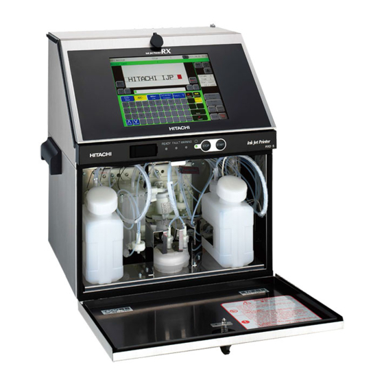
Thank you for purchasing the Hitachi IJ Printer Model RX2.
This printer employs a noncontact, ink-jet method to print onto a print target.
This instruction manual describes the basic operating procedures, maintenance procedures, and other detailed
handling procedures of the Hitachi IJ Printer Model RX2.
If the printer is improperly handled or maintained, it may not operate smoothly and may become defective or
cause an accident. It is therefore essential that you read this manual to gain a complete understanding of the
printer and use it correctly.
After thoroughly reading the manual, properly store it for future reference.
IF you changed the language of screen by mistake,see the chapter 7.8 "Selecting Languages".
Model RX2
Advertisement
Table of Contents

Related Manuals for Hitachi IJ RX2


Summary of Contents for Hitachi IJ RX2
-
Page 1: Technical Manual
HITACHI Printer Model RX2 Thank you for purchasing the Hitachi IJ Printer Model RX2. This printer employs a noncontact, ink-jet method to print onto a print target. This instruction manual describes the basic operating procedures, maintenance procedures, and other detailed handling procedures of the Hitachi IJ Printer Model RX2. -
Page 3: Safety Precautions
SAFETY PRECAUTIONS ● Before using the printer, thoroughly read the following safety precautions for optimum printer use. ● You should observe the precautions set forth below in order to use the product properly and avoid endangering you or other persons or damaging property. For the purpose of clarifying the severity of injury or damage and likelihood of occurrence, the precautions are classified into two categories, WARNING and CAUTION, which both describe hazardous situations that may arise if you ignore the precautions and perform an incorrect handling or operating... - Page 4 SAFETY PRECAUTIONS (Continued) WARNING ● Ensure that there is no flame- or arc-generating device around the printer. The ink and makeup are both flammable and may cause fire. Fire can be generated by matches, lighters, cigarettes, heaters, stoves, gas burners, welders, grinders and static electricity. Arcs may be generated from open-type relays, switches, and brush motors.
- Page 5 Read and understand the appropriate Safety Data Sheet (SDS) before using any ink or makeup. ● Use Hitachi approved consumables and periodic replacement parts. Using products that are not designated by Hitachi could cause s failure in certain functions. ● Warning for Mercury -- THE LAMP IN THIS PRODUCT CONTAINS MERCURY.
- Page 6 SAFETY PRECAUTIONS (Continued) WARNING ● When charging a refill of ink or makeup, exchanging ink, or otherwise handling ink or makeup, take enough care not to spill ink or makeup. If you spill any ink or makeup by mistake, wipe it off neatly and promptly with wiping paper or something similar.
- Page 7 SAFETY PRECAUTIONS (Continued) WARNING <Keep all fire away.> ○ Ink and Makeup are flammable. ○ All fire must be kept away from the machine. ○ Spilled Ink and Makeup must be wiped off and dried up immediately. <Caution when handling Ink/Makeup> ○...
- Page 8 (Continued) CAUTION ● Only persons who have completed an operator training course for Hitachi IJP can operate and service the printer. If the printer is operated or serviced incorrectly, it may malfunction or break down. ● Do not attempt to make repairs for any purpose other than operation or maintenance.
-
Page 9: Fcc Notice
SAFETY PRECAUTIONS (Continued) FCC Notice This device complies with part 15 of the FCC Rules. Operation is subject to the following two conditions: (1) This device may not cause harmful interference, and (2) this device must accept any interference received, including interference that may cause undesired operation. This equipment has been tested and found to comply with the limits for a Class A digital device, pursuant to part 15 of the FCC Rules. -
Page 11: Table Of Contents
CONTENTS 1. DELIVERED GOODS ......1-1 2. INSTALLING PRECAUTIONS ..... 2-1 3. - Page 12 5.3.9 On-line/Off-line Transmission Procedure ....... . . 5-33 5.3.10 Remote Operation Transmission ........5-34 5.3.11 Time control .
- Page 13 6.15 Long-term Shutdown ........6-33 6.15.1 Process prior to long-term shutdown .
-
Page 14: Delivered Goods
1. DELIVERED GOODS ●Unpack the equipment and check the delivered goods. Part Name Qty Product code. Remarks 1 IJ printer body 2 Basic Operation manual 3 Manual CD 4 One-page sheet Used in ink particles shape check, ink beam position check, 5 Magnifying glass 451274 etc. - Page 15 Part Name Product code Remarks Seal for power cable and 14 Cable seal external communications cable. Cable clip Nozzle rubber seal 15 Cable clip One page sheet 16 Plastic bag with zipper Use to store the one page sheet and nozzle rubber seal. Used for ink replacement and 17 Drainage tube 451676...
-
Page 16: Installing Precautions
2. INSTALLING PRECAUTIONS WARNING ● Ensure that there is no flame- or arc-generating device around the printer. The ink and makeup are both flammable and may cause fire. Fire can be generated by matches, lighters, cigarettes, heaters, stoves, gas burners, welders, grinders and static electricity. - Page 17 (9) When installing the print head and print head cable, comply with the following conditions. When positioning the end of the print head above the printer main body installation surface,ensure that the distance between the end of the print head and the installation surface does not exceed 1.5 m. When positioning the end of the print head below the printer main body installation surface, ensure that the distance between the end of the print head and the installation surface does not exceed 1 m.
- Page 18 (14) If you try to fix the print head with a magnetic substance (such as iron), the cover switch will malfunction resulting in an "Cover Open" error. This, you must only use nonmagnetic resins or metals for fixing the print head. (15) In the case of carrying the printer proper, use the handles in the drawing below.
-
Page 19: Installation Check Items
3. INSTALLATION CHECK ITEMS 3.1 Print head air purge If the makeup remains in the electrode section after cleaning or if you use the IJ printer at a high humidity, moisture condensation may occur within the print head, causing leakage from the deflection electrode section. It is also important to remember that dust or splashed ink accumulation on the deflection electrode section may cause leakage. -
Page 20: Setting Functions Which Can Be Performed
3.2 Setting functions which can be performed (1) Functions ●Sets whether or not each function is enabled or disabled for each login user. ●The operation buttons of disabled functions are not displayed or the screen cannot be entered. ●”User conditions setup” and “Using environment setup” can be started when the administrator logs in. ●The function restrictions state can be checked at the function restrictions screen. - Page 21 (2) Operation The administrator is logged in. Press Login management of the Environment setup menu. The Login management menu is displayed. Log in as a user with administrator rights when User conditions setup or Using environment setup are not displayed on Login management menu. Login management menu [Stop ] 2015.07.07 12:45...
-
Page 22: Select User
Select user5 . “user5” settings are displayed. [Stop ] 2015.07.07 12:45 User conditions setup Com=0 Modifies the user name. user5 ID:5 Manual Startup Administrator rights Users Administrator Displays the kind HOME protect Edit message access of administrator Select message access protect rights. -
Page 23: Password Protection Will Be Canceled In Units Of Print Item
3.2.1 Password protection will be canceled in units of Print item (1) General ●When Password protection is valid, it can be canceled in units of Print item. ●When Administrator logs in, Password protection can be canceled. (2) Operation ●The character input is made as follows. (Column 1) (Column 2) 14.... - Page 24 Press Edit message on “Change message” screen. “Edit message” screen will be displayed. Edit message [Stop ] 2015.07.07 12:45 Com=0 Message name[SAMPLE 1 ] Startup Manual − + HOME USE BY 14.02.20 abcde abcde Column 1 fghij fghij klmno klmno Item 1 Prev.item Next item Char.
- Page 25 Press Next item . The cursor moves to Column 2. Password protection [Stop ] 2015.07.07 12:45 Com=0 Message name[SAMPLE 1 ] Manual Startup − + HOME USE BY 14.02.20 abcde abcde fghij fghij klmno klmno Prev.item Next item pro- access tect access protect all Back Press access .
- Page 26 (3) Supplemental explanation ●The print data which was just edited shall be saved. After saved, when the data is selected, the character input will be available ONLY on Column 2. ● In case the number of Print lines is changed by Print format, the character input of ALL print items will be restricted.
-
Page 27: Selecting User When Power Is Turned On
3.3 Selecting user when power is turned on (1) Functions ●Sets whether or not to select a user which logs in when power is turned on. Possible login methods Login method “Disable” Login method “Enable” Immediately displays the Print Selects the user which logs in when Operation when power is description screen when the power the power is turned on. - Page 28 Press Using environment setup . The Using environment setup screen is displayed. When "Disable" is selected, Using environment setup [Stop ] 2015.07.07 12:45 Com=0 the Print description screen is immediately displayed when the power is turned on. Disable Enable Login method Startup Manual Default login ID : 1...
-
Page 29: The State Where The Administrator Login Is Returned Automatically
3.4 The state where the administrator login is returned automatically (1) Function details ●In case that Administrator logged in to printer and left the screen untouched for 15 minutes, the new function will switch the login condition to Users from Administrator. ●Flow diagram below shows the steps of switching to User login condition. - Page 30 (2) Operation Log in the administrator. Press Login management of the Environment setup menu. The Login management menu is displayed. Login management menu [Stop ] 2015.07.07 12:45 Com=0 Startup Manual Login history Select login user Password setup Sets function HOME restrictions for each user.
- Page 31 Press Administrator Automatic Deselect Enable . When "Disable" is selected, Using environment setup [Stop ] 2015.07.07 12:45 Com=0 the Print description screen is immediately displayed when the power is turned on. Disable Enable Login method Startup Manual Default login ID : 1 Admin HOME Administrator Automatic Deselect...
-
Page 32: Electric Signal Connection
4. ELECTRIC SIGNAL CONNECTION 4.1 Wiring precautions (1)If noise enters the IJ printer from the outside, there is the danger of erroneous operation or trouble. To improve noise resistance, perform wiring work as follows: Separate the power cable to the IJ printer from other power lines for powering use (especially, power line for a speed control inverter, etc.). - Page 33 (3) Precautions related to welding current of welder Signal (weak electric) ground and frame ground are connected because the ink drops of the IJ printer are electrically charged. The ink drops are electrically charged by impressing a volt- Nozzle Ink column Charge electrode age between the charging electrode and ink column as shown at the left.
-
Page 34: Input/Output (I/O) Signal Connection
4.2 Input/output (I/O) signal connection 4.2.1 Wiring the I/O line Open the top cover and run the I/O line wiring from the lead-in port on the side and connect it to external connection terminal boards 1 and 2 and the external communications connector inside the IJ printer. CAUTION When performing wiring work, always turn off the power. - Page 35 Lead-in port connection method Set screw [Lead-in port] Cable seal block Cable seal block Seal Lock nut Cable Seal Cable Remove the set screw and remove Remove the lock nut. the cable seal block from the body. Pass the cable through as shown Separate the cable seal block.
-
Page 36: Connection To Input/Output (I/O) Terminals
4.2.2 Connection to input/output (I/O) terminals [Overview of Terminals and Connectors] The terminal blocks and connectors for wiring are located behind the electrical access door (upper front panel door). External connection terminal block1 Communication connector CAUTION Faulty wiring causes the substrate breakdown. Before wiring, be sure to confirm the terminal signal. - Page 37 [ Connection to the external connection terminal block (TB1 of EZJ127 P.W.B) ] ● The I/F signal with conveyer is connected. ● NPN/PNP interface can be selected for the print target detector and a part of I/O signals. ● Totem pole/Open collector(NPN) can be selected for the encoder signal. ●...
- Page 38 EZJ127 board Input : PNP Input : NPN Output : PNP Output : NPN Input : PNP Input : NPN Output : NPN Output : PNP (Precautions when using combination of NPN/PNP interfaces) ● Use either NPN or PNP interface for input/output signals #4 to 5 and #14 to 23. Do not use a combination of the interfaces for these input/output signals.
-
Page 39: Input/Output (I/O) Specifications
4.3 Input/output (I/O) specifications When handling external signals, observe the voltage, current, and time given in this manual. Operation is not guaranteed if external signals are not handled properly. [Input / Output Signal Specifications] (1) Input signals (external device →IJ printer) Electrical characteristics No. -
Page 40: Print Target Detector Input
(2) Output signals (IJ printer →external device) Signal name Function Electrical characteristics Operates when the IJ printer is ready for Open collector (NPN) 1 Ready printing or in input mode. ● Sink current: 20 mA max. ● ON voltage: 0.5 V or less 2 Fault Operates when the IJ printer is fault state. - Page 41 (c) When NPN interface and dedicated power (d) When PNP interface and dedicated power supply are used supply are used Power Power DC24V DC24V DC24V Signal Signal Signal Signal 24VDC dedicated 24VDC dedicated power supply power supply Print target detector Print target detector ・SW1 "3": ON ・SW1 "3": OFF...
- Page 42 (3) Print target detector signal noise filter (a) IJ printer built-in noise filter setting. This function uses to filter the normal noise generated at the print target detector signal and noise generated by water drops, etc. with CR. The target sensor filter function (See “Instruction manual 4.14 Set the print specifications”) is effective against sensor chattering.
- Page 43 (4) Relationship between print object detection signal and printing operation 3 ms min. 3 ms min. Print object OFF ON detection signal Printing operation Printing Printing *Printing preparation time (Print start delay (Printing interval) adjustment = 0) *: The printing preparation time minimum Reference of printing preparation value varies with the print dot matrix, ink Nozzle size...
-
Page 44: Product Speed Matching Function Using A Rotary Encoder
4.3.2 Product speed matching function using a rotary encoder The product speed matching function is used when the speed of the print target or the conveyer carrying the print target changes while the IJ printer is printing. If this function is not used, when the speed changes, the width of the printed characters may change and the characters may be difficult to read. - Page 45 (3) Encoder wiring and setting of SW1 on EZJ127 PC board when used with a dedicated power supply ● Wiring used for a dedicated power supply differs according to output interface of the encoder, but can be the same depending on power supply voltage. (c) When open collector output and dedicated power (d) When totem pole output and dedicated power supply are used...
- Page 46 4.3.2-3 Method of calculating the conditions which allow product speed matching Calculate to find whether the Ink drop use and division factor are the conditions which allow product speed matching, based on the following. Print quality improves as the calculation shown below is performed and the Ink drop use becomes smaller. In addition, when changing Ink drop use, check the print quality.
- Page 47 (5) When a rotary encoder is used, the print character width cannot be changed by changing the IJ printer character width set value. When the print character width must be changed, a device (timing belt, pulley, etc.) which varies the conveyer speed and rotary encoder speed synch signal pulse frequency ratio must be installed.
- Page 48 Example 2: Calculate the diameter ratio (RT) of the pulley when the rotary encoder is connected to the conveyer through a pair of pulleys. Conveyer Pulley B Pulley A Diameter Encoder <Calculation conditions> ●Dot font 7 dots (horizontal direction 5, vertical direction 7) ×...
-
Page 49: Input Function
4.3.3 Input function The IJ printer can be controlled by inputting print stop, remote operation (“Startup”, “Shutdown”, “Reset”, “Deflection voltage control”) and reciprocative print switching to pins 4, 5, and 14 to 18 of TB1 by switch or contact signal from the outside. Internal circuit diagram (a) NPN interface input (no voltage input) Print stop... - Page 50 ●No-contact (transistor) Withstand voltage : 30VDC or greater Maximum drive current : 6mA or greater Residual voltage : 2V or less Leakage current : 0.1mA or less Drive method : Open collector Contact signal ● Use a relay whose contacts chattering at contacts ON/OFF is 2.0ms or less. 4.3.3-1 Print stop signal input [Function] This function prevents printing from the outside.
- Page 51 4.3.3-3 Remote startup signal input [Function] This function inputs the same operations as the IJ printer operation state operation keys (“Startup”, “Shutdown”, “Reset”, “Deflection voltage control”(standby state and Ready to print state switching)) by external switch or contact signal. (a) Judgment conditions (a-1) Remote signals in general Remote signal ON time t1 shall be 100ms or greater.
- Page 52 (a-3) “Reset signal” Input this signal when the fault signal is ON. In addition, after signal input, check if “Fault” is cleared. Turn on the “Reset signal” 30 seconds or longer after the IJ printer power is turned on. The time until the fault is cleared after the “Reset signal” is input t5: within 100ms Reset signal Fault signal...
-
Page 53: Output Function
4.3.4 Output function The state of the IJ printer is monitored by connecting the print output (“Print-in-progress” or “Print.complete”), online output, Ready, Fault, and Warning signals to pins 10 to 23 of TB1. (No-contact (transistor) output) Internal circuit diagram (a) NPN interface output (no-voltage output) Print output Online output Ready... - Page 54 4.3.4-1 Print output signal (NPN/PNP interface output : TB1-19) [Function] This function outputs a signal to the outside at IJ Printer Print.complete or Print-in-progress. (a) Print-in-progress and Print.complete switching Switching of the Print-in-progress and Print.complete signals is set at the User environment setup screen. (See Instruction manual “6.1 Set the user environment”.) (b) Signal timing Under 1s...
- Page 55 4.3.4-6 External communication (RS-232C) External equipment is connected to the IJ printer by serial communication of RS-232C. Pin No. Name Input/Output Remarks (NC) Input Output Connect with DSR by IJ printer side. Connect with DTR by IJ printer side. Connect with CTS by IJ printer side. Connects with RTS by IJ printer side.
-
Page 56: Product Speed Matching Function Without A Rotary Encoder (Rx2-S Only)
4.3.5 Product speed matching function without a rotary encoder (RX2-S only) 4.3.5-1 Auto product speed matching function Auto product speed matching function is used for detecting the change of speed of the conveyer carrying print target using the print target detector connected to the IJ printer, and prints each vertical line of the print according to the change of speed in the same way as the Speed matching function using a rotary encoder. -
Page 57: Communication (Optinal On Rx2-B)
5. COMMUNICATION (Optional on RX2-B) 5.1 Overview The functions described in this document are used to transmit printings and their registration numbers and enter them into the IJ printer with an external device connected to the IJ printer via an RS-232C serial communication line. - Page 58 (7) User pattern character transmission ● This function is used to transmit a user pattern and enter it into the IJ printer. ● A transmitted user pattern can be edited using the "Create user pattern" function, which is provided as an auxiliary function.
-
Page 59: Setting Communication Environment
5.2 Setting Communication Environment 5.2.1 Setting Communication Environment (1) Overview Function Description Default ● Comm. port is OFF : Offline mode when the power is turned on. ● Comm. port is ON : Online mode when the State at power-up power is turned on. - Page 60 (2) Operating procedure Press Communication environment setup from the Environment setup menu. The "Communication environment setup" screen appears. Comm. env. setup [Stop ] 2015.07.07 12:45 Com=0 State at power-up Comm. port in ON Warn. Fault Communication and signal error Manual Startup <Transmission condition by port>...
-
Page 61: Transmission Specifications
5.2.2 Transmission Specifications (1) Communication method : Half duplex (2) Startup method : Started up by host (3) Synchronization method : Asynchronous (4) Transmission method : Bit serial transmission (5) Baud rate : 150, 300, 600, 1,200, 2,400, 4,800, 9,600, 19,200, 38,400, 57,600, 115,200(bps) (6) Codes transmitted : Alphanumerical characters, symbols, dedicated characters,... -
Page 62: Transmission Sequences
5.3 Transmission Sequences 5.3.1 Common Transmission Sequences (1)Basic transmission operation. When ENQ and ACK are present: External device Text IJ printer When ENQ is omitted: External device Text IJ printer (2)When DC2 (retransmission) code is used (When no response is received though ENQ has been issued and yet the contents of print area switched) External device Text... -
Page 63: Printings Transmission
(9) Any data transmitted by communication (print contents, print specifications, print format, and user pattern) is not stored except in the following cases. [Conditions for storing the data] When the ink is stopped after communication by the Shut down key or a stop signal. At 01 minute of every hour. - Page 64 5.3.2-3 Printings ● An array of “character codes”. ● The coding system varies with the mode which is designated by the “Number of communication bytes” setting entered from the communication environment setup screen. User pattern Calendar Alphanumerical Number of Dedicated Punctuation characters, communication...
-
Page 65: Print Data Recall Transmission
5.3.3 Print Data Recall Transmission 5.3.3-1 Text Classification ESC2 Header 20H 1000s place 100s place 10s palce Units place Print data message number (0001 to 2000) [Existing machine message] Existing machine message can also be used. Header 56H 100s place 10s place Units place Print data message number (001 to 999) -
Page 66: Print Data Registration Transmission
5.3.4 Print data registration transmission 5.3.4-1 Text ● Specifies message number Classification ESC2 Header 21H 1000s place 100s place 10s place Units place Print data message number (0001 to 2000) ● Specifies registration No. and message name. Classification ESC2 Header 21H 1000s place 100s place 10s place... -
Page 67: Message Name
5.3.4-2 Message name (1) message number specified ● A message name is automatically attached when print data is registered. ● Based on the message name displayed in the upper left hand corner of the screen, the last 4 digits are replaced with the message number and used as the new message name. -
Page 68: Print Condition Transmission
5.3.5 Print Condition Transmission 5.3.5-1 Text (1)Line count / print format uniformity ESC2 Header 22H Classification 31H ● Line count and print format are made uniform for all print items. ● Line count of all rows are made uniform based on the first row. ●... - Page 69 (4)Print format text ● Line count and Line spacing Classification ESC2 Header 22H Line count Line spacing Line count (1 to 5) Line spacing (0 to 2) ● Character size and inter-character space Classification ESC2 Header 23H Character size 10s place Units place Inter-character space (0 to 28) Character size...
-
Page 70: Character Height
[Existing machine message] Existing machine message can also be used. ● Line count and Line spacing Character size Header 22H Line count Line spacing 30H:5 × 31H:5 × × Line count (1 to 5) 32H:7 Line spacing (0 to 2) ×... - Page 71 ● Character width Classification ESC2 Header 25H 1000s place 100s place 10s place Units place Character width (0000 to 3999) ● Character orientation Header 25H Classification Character ESC2 orientation Character orientation (0 to 3) ● Print start delay Header 25H Classification ESC2 1000s place 100s place...
- Page 72 ● Target sensor filter Classification ESC2 Header 25H Division Division (1:time setup, 2:until end of print) ● Target sensor filter setting value Classification ESC2 Header 25H 1000s place 100s place 10s place Units place Value (0000 to 9999) ● Ink drop charge rule Classification ESC2 Header 25H...
- Page 73 5.3.5-2 Text setup rules (1) Line count ● When you change the line count for a print item in a certain column, you must also set the line count for the other print items that belong to the same column. (Example) Setting items 7 and 8 to one line Transmit the line count consecutively to items 7 and 8.
- Page 74 (4) Bar code use and bar code type ● Two or more bar code types cannot coexist. ● When bar code set up is completed for a print item, its inter-character space can not be changed. (The inter-character space need not be transmitted in this case.) ●...
-
Page 75: Free Layout Transmission
5.3.6 Free Layout Transmission 5.3.6-1 Overview ● When Format setup is "Free layout", the selected print item can be moved individually. ● Free layout transmission shall be made independently. Free layout transmission can NOT be transmitted with Print format or Print specification or Print description. ●... - Page 76 (2)Specify Horizontal/Vertical directions and move ● Specify the number of dots for moving and the print item will be moved. ● Horizontal and Vertical move Item Classification ESC2 Header 24H (Contd.) number Item number (1 to 100) Horizontal 10000s 1000s place 100s place 10s place Unit place (Contd.)
- Page 77 5.3.6-3 Example of Free layout transmission (1) Specify Horizontal/Vertical coordinate and move STX ESC2 Header, Item No. Horizontal (X) Vertical (Y) classification coordinate coordinate [Transmission result] Print item 5: Horizontal (X) coordinate will be set to 120 and Vertical (Y) coordinate to 25. STX ESC2 Header, Item No.
- Page 78 (2) Specify Horizontal/Vertical directions and move STX ESC2 Header, Item No. Horizontal (X) direction Vertical (Y) direction classification [Transmission result] Move print item 10 rightward by 100 and upward by 20. STX ESC2 - - Header, Item No. Horizontal (X) direction Vertical (Y) direction classification [Transmission result] Move print item 20 leftward by 20 and downward by 5.
-
Page 79: Calendar Conditions Transmission
5.3.7 Calendar Conditions Transmission 5.3.7-1 Text (1) Calendar Conditions Transmission ● Offset Calendar Units Classification ESC2 Header 28H Type 1000s place 100s place 10s place block No. place Offset Calendar block No. Type (1 to 8) 30H : Year 31H : Month Offset setting range 32H : Day Setting item... - Page 80 (2) Count Conditions Transmission Count Setting ESC2 Header 2CH Classification block No. value Calendar block No. (1 to 8) Item name Setting value Classification Initial value Character code Range 1 Character code Range 2 Character code Update setting range (In progress) 000000 to 999998 Update setting range (Unit) 000001 to 999999 Increment setting range...
- Page 81 [Existing machine message] Existing machine message can also be used. (1) Initial value, Range, Jump from, Jump to, Reset Header 80H Item No. Type Setting value Code of type Initial value Range 1 Range 2 Jump from Jump to Reset ASCII ASCII is hexadecimal number.
-
Page 82: User Pattern Character Transmission
5.3.7-3 Example of count conditions transmission (1) Example of reset STX ESC2 Header, Count Reset value 00000 classification block No. [Transmission results] Defines reset value 00000 for count block 1. 5.3.8 User Pattern Character Transmission 5.3.8-1 Text ● When the number of communication bytes is set to "1" for communication Character ESC2 Header 32H Classification... -
Page 83: Character Size
5.3.8-2 Character size ● The character size is represented by the codes shown in the following table. 5.3.8-3 Pattern data (1) Pattern data length ● The pattern data length per character varies with the character size as indicated below. Character size code table No. - Page 84 × × Inter-character space data area : Unavailable area Inter-character space data area Note:The inter-character space is 1 dot at the maximum. × Inter-character space data area 5-28 ●Transmission Sequences...
- Page 85 × Inter-character space data area 3 (Chimney) 5 (Chimney) 5 (Chimney) × × × ●Transmission Sequences 5-29...
- Page 86 ● For pattern data composition purposes, the data is arranged in successive order, beginning from the bottom left, from bottom to top and from left to right. b) Pattern data example [For a character size of 5 × Unusable area 4 5 6 7 8 ●...
- Page 87 [For a character size of 18 × ● ● ● ● ● ● ● ● ● ● ● ● ● ● ● ● ● ● ● ● ● ● ● ● ● ● ● ● ● ● ● ● ● ● ● ● ●...
- Page 88 5.3.8-4 Character codes For character code designation, either ASCII codes or 2-byte codes are used. (1) ASCII codes (when the number of communication bytes is 1) User pattern character ASCII D9 DA DB DC DD DE DF User pattern character ASCII EA EB EC ED EE User pattern character...
-
Page 89: On-Line/Off-Line Transmission Procedure
5.3.9 On-line/off-line Transmission Procedure 5.3.9-1 Text (1) Change to online ESC2 Header 73H (2) Change to offline ESC2 Header 74H [Existing machine message] Existing machine message can also be used. (1) Change to online Header 79H (2) Change to offline Header 7AH ●... -
Page 90: Remote Operation Transmission
5.3.10 Remote Operation Transmission 5.3.10-1 Text Type 30H:Operation start ESC2 Header 72H Type 31H:Operation stop 32H:Deflection voltage control (ON) 33H:Deflection voltage control (OFF) 34H:Fault clear [Existing machine message] Existing machine message can also be used. Header 71H Type 5.3.10-2 Types of control Types of control for operation Type Content... -
Page 91: Time Control
5.3.11 Time control 5.3.11-1 Text (1) Date/time setup transmission ● Current time Header 1000s 100s Units Units Classification ESC2 place place place place place place (Contd.) Month Year Units Units Units Units place place place place place place place place Hour Minutes Second... - Page 92 [Existing machine message] Existing machine message can also be used. (1) Date/time setup transmission ● Current date/time Header 72H 1000s place 100s place 10s place Units place 10s place Units place (Contd.) Yaer Month 10s place Units place 10s place Units place 10s place Units place...
-
Page 93: Code Tables
5.4 Code Tables 5.4.1 Code Tables (1)Transmission control ASCII Name Description Code that is transmitted immediately before text. (start) Code that is transmitted immediately after text. (end) This enquiry code is used when the external device checks whether the IJ printer is ready for signal reception. This code must be transmitted before data transmission to the IJ printer. - Page 94 (2)ASCII codes High-order Low-order DLE Space ↑ ↑ ↑ ↑ STX DC2 ↑ ↑ ETX DC3 ↑ ↑ 年 月 ↑ ↑ ENQ NAK 日 ↑ ↑ & ↑ ↑ ↑ ↑ ↑ ↑ ↑ ↑ ↑ ↑ ↑ ↑ ↑...
- Page 95 Special characters (2-byte codes) (When special characters can be input) Characters Communication code F340 F341 F342 F343 F344 F345 F346 F347 F348 F349 F34A F34B F34C F34D F34E F34F Characters Communication code F350 F351 F352 F353 F354 F355 F356 F357 F358 F359 F35B F35C F35E F35F Characters...
- Page 96 Arabic characters (2-byte codes) Characters Communication code F44D F44C F44B F44A F449 F448 F447 F446 F445 F444 F443 F442 F441 F440 Characters Communication code F45B F45A F459 F458 F457 F456 F455 F454 F453 F452 F451 F450 F44F F44E Characters Communication code F465 F464 F463 F462 F461 F460 F45F F45B F45D F45C...
- Page 97 (4)User pattern characters (2-byte codes) Fixed size User pattern character 2-byte code F140 F141 F142 F143 F144 F145 F146 F147 F148 F149 F14A F14B F14C F14D F14E F14F User pattern character 2-byte code F150 F151 F152 F153 F154 F155 F156 F157 F158 F159 F15A F15B F15C F15D F15E F15F User pattern character 2-byte code F160 F161 F162 F163 F164 F165 F166 F167 F168 F169 F16A F16B F16C F16D F16E F16F...
- Page 98 (5)Punctuation characters (2-byte codes) Punctuation ‘ Space character 2-byte code F240 F241 F242 F243 F244 F245 F246 (6)Katakana (when KANA and dedicated characters can be input) Available character sizes × × × × × Inter-character 1 to 3 space (dots) Character codes table (2-byte code) (1)Character size 5x8, 7x10 834*...
- Page 99 (7)Calendar character code ● Set "calendar block starting character"as the first character and set "calendar block ending charater" as the last character. (Example) Calendar block Y Y M M D D Calendar block end character Calendar character Calendar block start character Total number Day of Yaer...
- Page 100 (Example 2) Example of when setting 2 calendar blocks to print item 1 02H 10H 31H 0FH F2H 60H F2H 50H F2H 51H F2H 51H F2H 52H F2H 72H 0EH (Contd.) Start STX DLE Calendar Calendar Calendar Calendar chracter chracter Calendar block 1 41H 42H 43H 0FH F2H 62H F2H 52H F2H 53H F2H 73H 0EH 03H Start...
- Page 101 Example of when performing printings transmission of count character (Example 1)Example of when setting a count block to print item 1 Start chracter Count Count End chracter Count block [Transmission results] : Count block range C C C C Print item1 : Count character (Example 2)Example of when setting 2 count blocks to print item 1 02H 10H 31H 0FH F2H 6AH F2H 5AH F2H 5AH F2H 5AH F2H 5AH F2H 7AH 0EH...
-
Page 102: Header Table
5.4.2 Header Table ESC2 Header Classification Data Type Header Classification Data section count Recall Message number 0001 to 2000 Message number 0001 to 2000 Registration Message name 1 to 12 Message name: Max 12 digits Line count, print format uniformity Line count : 1 to 5 Line count/Line spacing Line spacing: 0 to 2... - Page 103 Data Type Header Classification Data section count Calendar block : 1 to 8 Type : 0 to 4 Offset Offset : Yaer 0000 to 0099 (Year / month / day / hour Month 0000 to 0099 / minute) 0000 to 1999 Calendar Hour -023 to 0099...
-
Page 104: Communication Timing
5.5 Communication Timing 5.5.1 Signal Timing (1)In overwrite-protected mode On-line Off-line External device IJ printer ACK ACK ACK ACK (No signal output) Not ready Readiness Ready for for reception reception reception Print start signal Printing operation (a) When the IJ printer is off-line ●... - Page 105 (e) When a data transmission is aborted (the transmission of up to the ETX ● The IJ printer printings remain unchanged. For data retransmission, perform either of the following procedures. Transmit the DC2 (retransmission) code to the IJ printer. Press the Comm On/Off buttun to enter the off-line mode, and then switch back to the on-line mode. (2) In overwrite-enabled mode Off-line On-line...
- Page 106 (3) Switching print data with no occurrence of fault "Print data changeover in progress M" The following shows the method of use with no occurrence of "Print data changeover in progress M" when switching the print contents during transmission: (a) Print timing schematic diagram Print target Print target Print target...
-
Page 107: Response Time
5.5.2 Response Time 5.5.2-1 Time interval (T1) between external device communication and IJ printer response External device ……… IJ printer Baud rate (bps) T0 Maximum time (ms) 150 to 1200 2400 to 115200 (1) When Print format is set to "Individual" or "Overall" Time interval T1 when Print format is set to "Individual"... - Page 108 (2) When Print format is set to "Free layout" Time interval T1 when Print format is set to "Free layout" T1 Maximum time (ms) No. Transmission type Conditions Remarks Within 24 items 25 items or more The print message transfer ACK condition is t=fixed.
- Page 109 5.5.2-2 Time interval (T2) between IJ printer response and printing start External device IJ printer 5ms (*7) Print start signal Printing operation (1)When Print format is set to "Individual" or "Overall" Time interval T2 when Print format is set to "Individual" or "Overall" T2 Minimum time (ms) No.
- Page 110 Time T2 when there is a data matrix, QR code and GS1 DataBar setting T2 Minimum time (ms) Barcode type Character size Within 24 items 25 items or more N+20 × × Data matrix 16, 18 N+40 × × × QR (21 ×...
-
Page 111: Current Time Output Transmission
*7 If the communication time interval is not sufficiently secured, it may not operate normally. *12 When there is a data matrix, QR code and GS1 DataBar setting, the time is as follows: Time T2 when there is a data matrix, QR code and GS1 DataBar setting T2 Minimum time (ms) Barcode type Character size... -
Page 112: Communication Monitor Function
5.6 Communication Monitor Function ● The contents of serial communications between the external device and IJ printer are displayed. ● Up to 3,000 bytes of data can be acquired at a time. ● When you press the Start button, the system erases monitored data and acquires new data. ●... - Page 113 (3) Explanation of USB output function. ● When you press the USB output button, the Communication description which is displayed on screen can be output to a USB memory. ● The Communication description which is displayed on screen can be output to a USB memory. when "Comm.
-
Page 114: Warning Messages
5.7 Warning Messages ● If any communication is in error, the associated warning message appears below the status display area. ● Note the message to confirm the error and then take remedial action as appropriate for the indicated error code. Warning Print description [Ready ]... - Page 115 Error Name Description Check code 014 Parity error The parity error occurred. Check the baud rate and data format. Print format code Check the print format transmission text The print format data value was illegal. error section. 016 Overrun error The overrun error occurred.
- Page 116 Error Name Description Check code ● While "Create messages" function was operating, on-line transmission was performed. Create messages ● On-line transmission was performed Check the timing of on-line error when print data which was controlled transmission. separately from data created and registered by print description screen, was present.
-
Page 117: Precautions
5.8 Precautions 5.8.1 Notes on Product speed matching Feature Use (1) If the product speed matching signal cannot be entered during printing, the printing state continues to prevail so that communication may not be established (no response can be made). If such a situation is encountered, perform procedure below. -
Page 118: Communication Buffer
5.9 Communication Buffer 5.9.1 Overview (1) Print content transmission ● The print contents received through print content transmission will not be reflected in printing immediately, but will be temporarily held in buffer. ● The print contents are fetched from the buffer one by one for each printing, and reflected in subsequent printing. -
Page 119: Description Of Functions
5.9.2 Description of Functions (1) Application procedure ● Prepare the following in advance: Preliminary Preparation Items Procedure Specify "overwrite-enabled" for communication mode on the communication environment screen. In addition, specify "t=fixed" for print message transfer ACK. Set the buffer function on the second page of the communication environment setting screen to "enable."... - Page 120 (2) Buffer ● The print content receive buffer has a queue structure (beginning with oldest data, in sequence). ● Print content is fetched from the buffer for each printing. ● Once the Ready status is set, the first print content will be fetched from the buffer. ●...
- Page 121 (Example 3) When offline is restored during normal operation, and printing is subsequently performed in standard mode: Online External device IJ printer Ready Printing (Example 4) Buffer repeat count is 2. External device IJ printer Printing (Example 5) Timing of Fault : Print completed, Data count when error occurs : 2 External device IJ printer Printing...
-
Page 122: External Communications
5.9.3 External Communications 5.9.3-1 Transmitting print contents (1) Function ● The received print content will not be reflected in printing immediately, but temporarily held in buffer. Item External device Content IJ printer ● To facilitate operation, first input fixed characters that do not need to be changed, and then transmit only the print items to be changed. -
Page 123: Errors
5.9.4 Errors (1) Errors during external communications Errors during print content transmission and print data call-up Condition Type of error NAK is returned. Not all received print contents could be held in buffer because However, this will not cause any its capacity was exceeded external communication error. -
Page 124: Circulation System Work And Adjustment
6. CIRCULATION SYSTEM WORK AND ADJUSTMENT METHOD WARNING ● Never pour the ink and makeup waste into a sewer, etc. Have the ink and makeup drainage processed by an industrial waste processor as special control industrial waste and used wiping papers and the empty container as industrial waste. -
Page 125: Circulation Control Screen Operation
6.1 Circulation control screen operation Start from the Maintenance menu. Perform menu 1 and menu 2 switching using Prev. menu and Next menu . Circulation control [Stop ] 2015.07.07 12:45 Com=0 Eject ink Cleaning stop No-cleaning stop (Goes to Standby) HOME Recovery-line 1st menu Nozzle backwash... -
Page 126: Circulation Control Contents
6.2 Circulation control contents ● During generation of an “Main Ink Tank Too Full” fault, input from any of the keys is not accepted. Perform operation after referring to par. “6.13 Draining ink from the main ink tank” and clearing the fault. ●... -
Page 127: Replacing The Ink
6.3 Replacing the ink (1) Overview ● This operation is performed when replacing old ink with new ink. ● Consecutively performs from ink drainage to ink replacement to ink refilling. ● Do not perform this operation while ink is being ejected. Perform it after setting the IJ printer to the “Stop” state. - Page 128 ● Remove the recovery tube, connect it to the accessory drainage tube and put it into the beaker. Recovery tube Drainage tube Keep the drain tube clean with makeup after it is used. Otherwise, the pressure in the recovery line rises by the clogged ink, and it may cause a damage of the circulation pump.
- Page 129 b) Press the Start/Continue key. The ink in the printer is drained from the drainage tube. ● To abort the sequence, press the Abort key. Then, follow the on-screen instructions to return the recovery tube to its original position and press the Start/Continue key . You are then returned to the "Circulation control"...
- Page 130 b) Remove the cap, then drain the ink remaining in the ink reservoir. * Clean the inside of the reservoir with makeup. CAUTION If ink is accidentally spilt, wipe it up promptly with wiping paper or Ink reservoir something similar. In addition, do not close the maintenance cover until you are Beaker...
- Page 131 h) Set the ink filter. 2015.07.07 12:45 Circulation control [Service ] Com=0 Ink Drainage Process:Ink replacement Ink rep. Operation guide Ink refill Confirm the ink filter is set at the right position. Press [Start/Continue]. Abort Start/Continue Proc. status: ● Set the ink filter as follows.(Piping D is on the right.) Piping(D) Ink filter i) When Start/Continue is pressed, refilling of the lines with ink begins.
-
Page 132: How To Correct Ink Stream Bending And Nozzle Clogging
6.4 How to correct ink stream bending and nozzle clogging WARNING ● Wear protective gear (goggles and mask). ● If the ink or makeup gets in your eyes or mouth, immediately rinse with warm water and consult a doctor. ● Perform work after confirming that there is no one in the ink ejection direction. (Perform this work by inserting the print head tip into a beaker, etc.) 6.4.1 Nozzle backwash ●... - Page 133 Suction ends in about 1 minute and the screen returns to the Circulation control screen. ● To stop operation, press Abort . Check if ink stream bending or nozzle clogging has been repaired. ● Display the screen after the Circulation control screen. 2015.07.07 12:45 Circulation control [Stop ]...
-
Page 134: Nozzle Orifice Disassembly And Cleaning
6.4.2 Nozzle orifice disassembly and cleaning ● This is the processing method when ink stream bending or nozzle clogging is not repaired even when nozzle backwash was performed. ● Do not perform this work while ink is being ejected. Perform it after setting the IJ printer to the Stop state. - Page 135 Clean the nozzle section. Using the cleaning bottle, pour the makeup over the nozzle section to clean it, from which the nozzle orifice has been removed. Cleaning bottle Beaker Install the nozzle orifice. a) Use the tweezers to hold the O-ring and put it into the nozzle body.
- Page 136 Remove the nozzle orifice once and make sure that the O-ring has been installed. O-ring Attach to the groove Remove the nozzle orifice, and use the four screws to secure it. ● Use the four screws to secure the nozzle orifice so that the characters on it face up.
-
Page 137: Stream Alignment
6.5 Stream alignment WARNING ● Wear protective gear (goggles and mask). ● If the ink or makeup gets in your eyes or mouth, immediately rinse with warm water and consult a doctor. ● Perform work after confirming that there is no one in the ink ejection direction. (Perform this work by inserting the print head tip into a beaker, etc.) This operation is performed when the nozzle or nozzle orifice has been replaced. - Page 138 Adjust the horizontal direction and vertical direction positions. (a) Horizontal direction adjustment procedure Slightly loosen the horizontal direction lock screws (2). As to the screw loosening, please see the precautions below. Turn the horizontal direction adjustment screw and adjust the position of the makeup. When you want to move in the minus electrode direction : Turn clockwise When you want to move in the plus electrode direction...
-
Page 139: Cleaning The Gutter
6.6 Cleaning the Gutter ● When the ink recovery system becomes dry or clogged, the line from the gutter to the ink main tank can be cleaned by performing “Gutter cleaning”. ● Do not perform this operation while ink is being ejected. Perform it after setting the IJ printer to the “Stop” state. -
Page 140: Replacing The Ink Filter
6.7 Replacing the ink filter Perform it in a state in which the ink has been drained. The ink is not wasted if performed simultaneously with the ink replacement. Display the Circulation control screen and press the Ink filter replacement → Start/Continue . - Page 141 ● Remove the recovery tube, connect it to the accessory drainage tube and put it into the beaker. Recovery tube Drainage tube Keep the drain tube clean with makeup after it is used. Otherwise, the pressure in the recovery line rises by the clogged ink, and it may cause a damage of the circulation pump.
- Page 142 When the operation guide “Replace ink filter -----” is displayed, replace ink filter with a new one. 2015.07.07 12:45 Circulation control [Service ] Com=0 Process:Ink filter replacement Ink Drainage Ink rep. Operation guide Ink refill Replace ink filter with a new one. Put ink into the ink reservoir.
- Page 143 b) Set the ink filter as follows. (Piping joints D is on the right.) Piping joints(D) Ink filter c) Fill the reservoir with new ink. (d) Insert the tip of the print head into a beaker. ● Prepares for bending of the ink stream. Refill the IJ printer with ink ●...
- Page 144 Open the Parts usage time mgmt. screen (menu 2 of the Circulation control screen), and set the Ink filter time to “0”. Parts usage time mgmt. [Stop ] 2015.07.07 12:45 Com=0 (hours) (hours) Ink filter 00000 00000 Pump 01000 Recovery filter 00000...
-
Page 145: Replacing The Recovery Filter
6.8 Replacing the recovery filter ● Do not perform this operation while ink is being ejected. Perform it after setting the IJ printer to the “Stop” state. Pull out the makeup reservoir. Recovery filter Makeup reservoir Pull out Rotate the lock nut of the recovery filter and pull it forward and out. Lock nut CAUTION If ink is accidentally spilt, wipe it up... - Page 146 Open the Part usage time mgmt. screen (menu 2 of the Circulation control screen) and set the Recovery filter to “0”. Parts usage time mgmt. [Stop ] 2015.07.07 12:45 Com=0 (hours) (hours) Ink filter 00000 01000 Pump 01000 Recovery filter 00000...
-
Page 147: Replacing The Circulation Filter
6.9 Replacing the circulation filter ● Perform it a state in which the ink has been drained. The ink is not wasted if performed simultaneously with the ink replacement. Perform -(a) to -(c) of the procedure in “6.3 Replacing the ink”. ●... -
Page 148: Adjusting The Pressure
6.10 Adjusting the pressure ● Check the pressure before printing state check at the start of operation. ● Do not perform this operation in the Stop state. Perform it in the state in which ink is ejected. Open the Operation management screen. Operation management [Ready ] 2015.07.07 12:45... -
Page 149: Excitation V Adjustment
6.11 Excitation V adjustment (1) Overview ● The Excitation V set value is 0 to 19. The state of the ink drops is different for each setting. ● The optimum Excitation V set value must be input to maintain good print quality. ●... -
Page 150: Print Data
Print data Select the contents and conditions of the characters to be printed. Data to be displayed Print data For test Prints using the currently set print description and print conditions. Prints using the following test conditions: ・Number of lines : 1 line ・Character size : 12... - Page 151 Perform nozzle property test printing. ● When “Print trigger source” is , press Start printings . Button input When “Print trigger source” is , input the sensor signal. Sensor CAUTION ● During the nozzle property test, the state of creation of the ink drops may become poor and an “Ink Drop Charge Too High”...
-
Page 152: Ink Drop State Check Method
6.12 Ink drop state check method ● The state of the ink drops can be checked by using a magnifying glass. ● Perform this work in the Eject ink state. WARNING ● Wear protective gear (goggles and mask). ● If the ink or makeup gets in your eyes or mouth, immediately rinse with warm water and consult a doctor. - Page 153 Ink drops creation state confirmation table Ink drop shape Judgment Name Remarks A mode Good B mode Perfect High-speed small-diameter mode Allowable Two or fewer small-diameter drops Constant-speed small-diameter allowed mode Low-speed small-diameter allowed mode When the shape of the ink drops is not allowed, update to the optimum set value at par. “6.10 Excitation V adjustment”...
-
Page 154: Draining Ink From The Main Ink Tank
6.13 Draining ink from the main ink tank ● When the main ink tank full fault is generated, the ink cannot be drained by screen operation. Drain the ink and refill with new ink as follows: Remove the drain tube of the main ink tank as shown in the figure below and drain the ink in the tank by approximately 50 ml. -
Page 155: Test Of Solenoid Valve/Pump
6.14 Test of solenoid valve/pump ● The operation confirmation of solenoid valve and pump is performed. Supply valve (MV1) Replenishment valve (MV2) Recovery valve (MV3) Agitation valve (MV4) Circulation valve (MV5) Pressure relief valve (MV6) Makeup valve (MV7) Cleaning valve (MV8) Shutoff valve (MV9) -
Page 156: Long-Term Shutdown
6.15 Long-term Shutdown CAUTION ● A special work is required to perform the Long-term Shutdown procedure. It is recommended to contact your local distributor and ask for the work. Should you desire to conduct the work by yourself, the cautions must be fully understood beforehand. -
Page 157: Process Prior To Long-Term Shutdown
6.15.1 Process prior to long-term shutdown (1) Overview ● This operation is the storage work performed when the IJ printer is shut down for exceeding the period indicated in Table 1. ● The storage procedure for long-term shutdown is completed by draining the ink from the ink circulation system and cleaning it with the makeup. - Page 158 Open the "Circulation control" screen, and press the Process prior to long-term shutdown key and the Start/Continue key. Circulation control [Stop ] 2015.07.07 12:45 Com=0 Eject ink Cleaning stop No-cleaning stop (Goes to Standby) HOME Recovery-line Nozzle backwash cleaning Prev.Dsp. Next Dsp. Ink filter Ink replacement Ink circulation...
- Page 159 (a) Drain the ink ejected into the beaker, clean the beaker and then put 50ml of the makeup and a tube connection block into the beaker. CAUTION If ink is accidentally spilt, wipe it up promptly with wiping paper or equivalent.
-
Page 160: Startup Process After Long-Term Shutdown
6.15.2 Startup process after long-term shutdown [Overview] ● This operation is the work for draining the makeup which cleaned the ink circulation system at "Process prior to long-term shutdown" and the work for refilling it with the ink. ● To completely drain the makeup from the circulation system, you should charge the circulation system with the ink, drain the ink, and refill the ink into the system. - Page 161 (e) Open the "Circulation control" screen, and press the Ink stream alignment key and then the Start/Continue key. ● Check if the ink stream is going into the gutter and it’s in the center of the gutter. ● Check whether the gutter absorbs the liquid. CAUTION If the ink is not being ejected, press Ink stream alignment key again.
- Page 162 Open the "Operation management" screen. Arbitrarily rotate the handle of Pressure-reducing valve clockwise/counterclockwise and check if the pressure changes. After confirming the change, adjust the valve and set the Ink pressure to standard setting with a tolerance of 0.002. Operation management [Ready ] 2015.07.07 12:45 Com=0...
-
Page 163: Maintenance Service
7. MAINTENANCE SERVICE ● For the IJ printer to operate smoothly, the following maintenance work is necessary. (1)Replacement of consumables Replace the following filters according to the “Replacement guideline”. Consumable Replacement guideline Replacement procedure description Ink filter 2,400h "6.7 Replacing the ink filter" Recovery filter 1,200h "6.8 Replacing the recovery filter "... -
Page 164: Replacing The Air Filter
Replacing the air filter Trun off the power. Loosen the knobs (thumb screws) and remove the intake fan cover. Intake fan cover Knob (thumb Screw) Remove the old filter and set the new filter. (Please set the new filter with red-mark being invisible.) Air filter Red-mark inside Set the intake fan cover. - Page 165 Open the Part usage time mgmt. screen (menu 2 of the Circulation control screen) and set the time of the air filter to “0”. Parts usage time mgmt. [Stop ] 2015.07.07 12:45 Com=0 (hours) (hours) Ink filter 00000 01000 Pump 01000...
- Page 166 “Performance parts for repair” are parts necessary to maintain the functions of the product. Please fill in for later use. Customer memo: Useful when communicating with the service in charge. Your Hitachi sales representative: Tel: Person in charge: Your Hitachi distributor:...
-
Page 167: Schematic Diagrams
8. SCHEMATIC DIAGRAMS 8.1 Outside Dimensions ●Outside Dimensions 8-1... - Page 168 8-2 ●Outside Dimensions...
-
Page 169: Electrical Connection Diagram
8.2 Electrical Connection Diagram ●Electrical Connection Diagram 8-3... - Page 170 8-4 ●Electrical Connection Diagram...
-
Page 171: Circulation System Diagram
8.3 Circulation System Diagram ●Circulation System Diagram 8-5... -
Page 172: Appendix
9. APPENDIX Bar code, 2-dimensional code ● See “4.7.5 Print a bar code” and “4.14.3 Set various printing” in the Instruction Manual. (1) Precautions when using EAN-13 code ● When bar code is “EAN-13” and “EAN-13 Add-On 5" the area for inputting the 2-digit “country code” is displayed on the print format screen. - Page 173 (3) Precautions when using code 128 ● The 2 modes include Code set B (Alphanumeric, numbers, symbols) and Code set C (numbers only). The mode can be changed by pressing “Code B” or “Code C” on the keyboard. ● In the case of continuous numbers, the bar can be shortened by setting to code set C. ●...
- Page 174 (Example 2) Example of Character input for DM 16 × Doable or not Print contents Number of characters Digit calculation result (DM16 × 123456789012345678901234 24 characters 12 digits Doable. Result is less 1 digit 1 digit ・ ・ ・ ・ ・ ・ ・ ・ ・ ・ ・ ・ ・ ・ ・ ・ than or equal to 1234567890123456789012A maximum of 12 digits.
- Page 175 (5) Precautions when using QR Code and Micro QR ● Set as shown below for print item to which QR code or Micro QR is to be set: (i) Number of lines : 1 line (ii) Character size : 18 24, 24 32 (for QR code), 12 16 (for Micro QR)
- Page 176 (6) Precautions when using GS1 DataBar(Limited, Omnidirectional, Staced) code ● Thirteen(13) characters can be inputted. When a GS1 DataBar Limited is set, the heading character shall be 0 or 1 (zero or one). ● When adding Readable code (number; human readable code), select either 5 5 or 5 7 as the size of the ×...
-
Page 177: Setting High-Speed Printing
Setting high-speed printing (Optional on RX2-S) (1) Overview ● Three modes of HM, NM or QM can be selected. By selecting the mode, high quality printing result can be ensured according to the line speed. HM mode NM mode Remarks HM mode is equivalent to particle use percentage of 1/1. -
Page 178: Change Of Buttons, Icons And Status Colors
Type of high-speed print and number of vertical dots used ● Number of vertical dots used in high-speed print is shown in Table below. ● When calculating printing preparation time, etc., pay attention to number of vertical dots. umber of vertical dots used in the nozzle diameter is 65 μ... - Page 179 ● “Ready” state → “Standby” state switching ● With the conveyor interlock being activated by “Ready” signal, should this “Ready” signal be turned to “Standby”, the conveyor will stop. Press Ready and the message “Print Abort Confirmation” appears. Ready Then press OK .
- Page 180 (2) Change of Icons ● The icons displayed on touch screen will be changed. ● With this change, the icons displayed on the screen can be seen easily. ● For icon type selection, please contact your local distributor. ● Icons displayed or not is set by “ICON Display” [Enable] or [Disable] on touch screen setup. Supported Icons Icon Type Example...
- Page 181 (3) Change of Status Color ● The background color of IJP status will be changed. ● With this changes, the background color of “Ready” will be green which is the same color as the status indicator light. Background Colors of IJP Status Status Color State Before Change...
-
Page 182: Icon List
Icon List (1) Operation Control Buttons Group Icon List 1 - Operation Control Buttons Group Icon Button Name Default English Japanese No Text Startup Shutdown Manual Com=0 Com=1 HOME Apply (2) Common Buttons Group Icon List 2 - Common Buttons Group Icon Button Name Default... - Page 183 (3) Keyboard Buttons Group Icon List 3 - Keyboard Buttons Group Icon Button Name Default English Japanese No Text Change Change V 123/Sign Logo Accent 1 Accent 2 Greek Russian 1 Russian 2 Arabic 1 Arabic 2 Arabic number Dedicated Kana Kana Convert Pinyin Convert...
- Page 184 (4) Mini-Keyboard Buttons Group Icon List 4 - Mini-Keyboard Buttons Group Icon Button Name Default English Japanese No Text Logo Special 1 Special 2 Arabic number Kana (5) Print Format Screen Buttons Group Icon List 5 - Print Format Screen Buttons Group Icon Button Name Default...
-
Page 185: Index
INDEX 2-Dimensional code ..............9-1 Air purge . - Page 186 Ink circulation ..............6-3 Ink drainage .
- Page 187 QR code ............5-51, 5-52, 5-54, 5-55, 9-4 Recovery filter .
- Page 188 2-L3009-4B...