Table of Contents
Advertisement
Quick Links
Advertisement
Table of Contents
Troubleshooting

Related Manuals for Hitachi IJ PH


Summary of Contents for Hitachi IJ PH
-
Page 1: Service Manual
Service Manual HITACHI Printer Model PH Revision Aug. 2011 Version First edition... - Page 2 [ Revision of PH service manual ] Revision Chapter Revised Page − − − −...
- Page 3 Contents 1. Introduction ····················································································································1-1 1.1 Safety precautions ·································································································1-1 1.2 Structure of each part in the main body ·································································1-7 1.2.1 External views (PH-D)·······················································································1-7 1.2.2 Main body internal (PH-D) ················································································1-8 1.2.3 Print head ········································································································1-9 1.3 Installation ··············································································································1-10 1.3.1 Wiring of power supply ····················································································1-10 1.3.2 Installation procedure (PH-D) ···········································································1-13 2.
- Page 4 3. Maintenance of controlling part ·····················································································3-1 3.1 Construction of controlling part ·············································································3-1 3.2 Controller part ·········································································································3-3 3.2.1 EZJ124 board (controller board) ·······································································3-3 3.2.2 Battery ···············································································································3-7 3.2.3 Power supply for LCD backlight········································································3-8 3.2.4 Control panel ·····································································································3-8 3.2.5 Front panel assembly Replacement Procedure ··············································3-9 3.2.6 LCD assembly Replacement Procedure···························································3-13 3.3 Engine part···············································································································3-18 3.3.1 EZJ93 board (MPU board)················································································3-18...
- Page 5 5. Print head-related maintenance ····················································································5-1 5.1 Outline structure of print head and how to remove each cover ······························5-1 5.2 Nozzles Replacement Procedure (appendix: nozzle drive conditions) ···················5-2 5.3 Deflecting base Replacement Procedure································································5-6 5.4 Cover switch Replacement Procedure ····································································5-9 5.5 Sealing valve (MV9) Replacement Procedure ························································5-10 5.6 Heating unit Replacement Procedure······································································5-12 5.7 Gutter base group Replacement Procedure····························································5-13 5.8 Head base Replacement Procedure ·······································································5-14...
-
Page 6: Safety Precautions
1. Introduction 1.1 Safety precautions Before starting the maintenance and inspection work of this printer, thoroughly read and understand the “safety precautions”. When explaining the product to customers at the time of the installation, fully explain the “safety precautions”. ● Before using the printer, thoroughly read the following safety precautions for optimum printer use. - Page 7 SAFETY PRECAUTIONS (Continued) WARNING ● Ensure that there is no flame- or arc-generating device around the printer. The ink and makeup are both flammable and may cause fire. Fire can be generated by matches, lighters, cigarettes, heaters, stoves, gas burners, welders, grinders and static electricity. Arcs may be generated from open-type relays, switches, and brush motors.
- Page 8 ● The printer must be managed in compliance with all appropriate regulations. ● Use Hitachi approved consumables and periodic replacement parts. Using products that are not designated by Hitachi could cause s failure in certain functions.
- Page 9 SAFETY PRECAUTIONS (Continued) WARNING ● When charging a refill of ink or makeup, exchanging ink, or otherwise handling ink or makeup, take enough care not to spill ink or makeup. If you spill any ink or makeup by mistake, wipe it off neatly and promptly with wiping paper or something similar.
- Page 10 For information on handling, see the Material Safety Data Sheet (MSDS). The MSDS can be accesses from the following web site or from our sales office. URL http://www.hitachi-ies.co.jp/ijp ● If extraneous noise enters the printer, it may malfunction or break down.
- Page 11 SAFETY PRECAUTIONS (Continued) CAUTION ● When handling PC boards and electric parts, be careful of static electricity. PC boards and electric parts mount elements weak against static electricity. When handling PC boards and electric parts remove the static electricity by wearing a suitably grounded anti-static wrist band.
-
Page 12: Structure Of Each Part In The Main Body
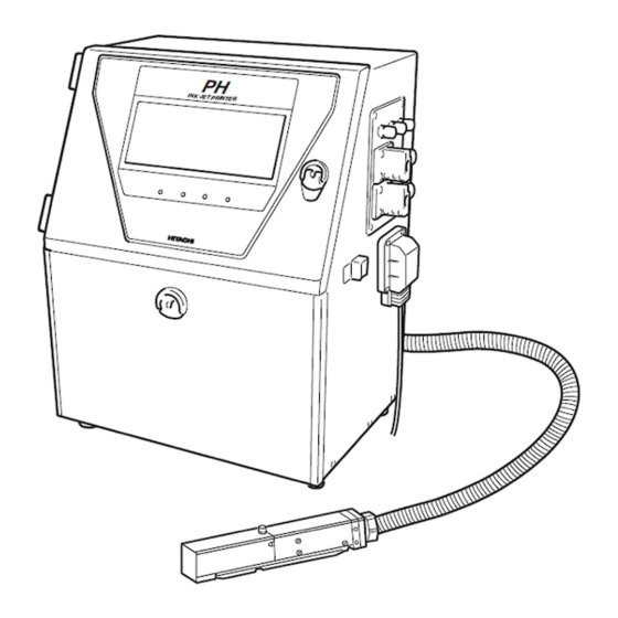
1.2 Structure of each part in the main body 1.2.1 External views (PH-D) Exhaust duct connection port Air-purge connection port See section "1.2.6, Print head air purge" in the instruction manual. - Page 13 1.2.2 Main body internal (PH-D)
- Page 14 1.2.3 Print head 1.3.5 Print head Note: Meaning of orifice plate lot number 6 A12345 Position of lot number Serial number Nozzle diameter 6: 65μm Orifice plate...
-
Page 15: Installation
1.3 Installation 1.3.1 Wiring of power supply Caution ・Be sure to use an appropriate plug and connect a protective ground. ・Place a wall socket in the vicinity of the unit so as to easily remove it. ・Use a power cable within the designated specifications. ・Do not bundle a signal level cable and a power cable together outside the unit so that the signals (signal terminal block, a connection signal to an external communication connector) are not affected by a noise from... - Page 16 (1) Remove the Inlet cover.(Fixing screw 4 locations) Inlet cover (4 fixed screws) (2) Insert the power cable to the Inlet. Power Cable 1-11...
- Page 17 (3) Mount the inlet cover. Inlet Cover CAUTION Power cable Tape the seal around the outside of the cable and as in the drawing, and insert it into the holder as shown in above. 1-12...
- Page 18 1.3.2 Installation procedure (PH-D) Perform an installation work of the unit according to the following procedure at the unpacking. Step Work Related page Selection of ink type 2.2 System environment (Touch screen operation) setup Makeup ink replenishment Instruction manual 7.4 Makeup ink replenishment Ink stream alignment Instruction manual...
-
Page 19: Maintenance Work
2. Maintenance work A screen for use in the maintenance work by a service personnel is described. 2.1 Setting of maintenance mode by service personnel For the maintenance work by a service personnel, restrictions on use of the following functions are removed. - System environment setup - Adjustment/operational checkout - Solenoid valve/pump test... - Page 20 3 When passing the password judgment, the "service personnel maintenance" is displayed and therefore, select "0" and press the Back key. Caution After the completion of the service maintenance work, be sure to return the setting of the “service personnel maintenance” to “1” (protect) (when the power supply is turned off, the display of the “service personnel maintenance”...
- Page 21 View alarm history The alarm log can be cleared by the clear key. screen Circulation control The viscometer calibration screen can be selected. menu Parts usage time The time of the pump and the solenoid valves can be management changed. Unit information The serial number and the ink coefficient can be changed.
-
Page 22: System Environment Setup
2.2 System environment setup -The setting with respect to the system environment of the IJ printer is performed. Ink type Cable length Nozzle size Ink temperature correction Excitation frequency Excitation curve Ambient temperature upper/lower limit The memory card with the IJP system is necessary to change the nozzle size. This setting is performed in the IJ printer "stop"... - Page 23 3 After the completion of the setting, when Back is pressed, the screen returns to the maintenance menu. Conditions set by the ink type*1 Excitation Operating Operating Excitation Nozzle size Ink type frequency temperature temperature curve (kHz) upper limit ( lower limit ( JP - K67 68.9...
-
Page 24: Adjustment/Operational Checkout
2.3 Adjustment/operational checkout 2.3.1 Excitation adjustment - Adjust the drive conditions of nozzles. - This adjustment is performed in a state other than the IJ printer “ready” state. - Be sure to perform this adjustment in the case of replacing the board (EZJ93, 106, 124), the nozzle (including the print head) or changing the ink type. - Page 25 3 When the automatic adjustment is not normally completed, the following factors are considered. Confirm whether or not each part is normal. - The connection of EZJ93 board and EZJ106 board is insufficient. - The dip switch on the EZJ106 board is wrongly set. - The connection of a coaxial cable connector for excitation (EZJ106 CN5) is insufficient.
-
Page 26: Charging Voltage Confirmation
2.3.2 Charging voltage confirmation With respect to the - This confirmation is performed in a “Stop“ state. password protection, - Confirm when performing the board exchange (EZJ93 and 106). refer to 2.1 setting of service personnel 1 Press adjustment/operational checkout at the second page of the maintenance mode. -
Page 27: Phase Margin Test
2.3.3 Phase margin test - Perform the phase margin test of a nozzle. - This test is performed for checking that (1) whether or not the nozzle is in a printable state (whether or not clogging is present) and (2) whether or not ink is deteriorated. - After the setting of a “standby”... - Page 28 3 Select the print timing from Button input or Sensor and the print data from For test or Data to be displayed on the screen, respectively. ・When the “Button input” is selected, the following figure is displayed and the printing phase is sequentially printed from 0 phase to 15(f) phase every time Start Printing is pressed.
- Page 29 When you want to stop the printing in midstream, the printing can be interrupted by selecting Abort. ・When selecting “For test”, the printing conditions are automatically set as described below. Number of line : one line Character size : 12×16 dots Inter-char.
-
Page 30: Auto Phase Gain Adjustment
2.3.4 Auto phase gain adjustment - The gain of the auto phase detection voltage is automatically adjusted. - Perform this adjustment after confirmation that the periphery of a gutter part within the nozzle head is not made dirty with ink or the like and the printing head cover is correctly fixed. - Page 31 3 After the completion of the automatic adjustment, when the Back key is pressed, the auto phase detection voltage is output and therefore, confirm the waveform by an oscilloscope. With respect to positions of Using the oscilloscope, confirm that the voltage of TP1 (APH signal) on the EZJ106 the board and the test pin, board is from 8 to 10 V as the maximum voltage, 2 V or less as the minimum voltage, refer to "...
-
Page 32: Level Sensor Confirmation
2.3.5 Level sensor confirmation - The operation confirmation of level sensor in the main ink tank is performed. (1) Too high (2) Initial level - The operation confirmation of level sensor in the ink reservoir is performed. (1) Too low - The operation confirmation of level sensor in the makeup ink reservoir is performed. -
Page 33: Heating Unit Confirmation
2.3.6 Heating unit confirmation - The operation confirmation of heating unit is performed. (1)Heating unit power ON/OFF. - A display of an ambient temperature and a heating unit temperature is performed. - Perform this operation confirmation in a state other than "ready" state. 1 Press adjustment/operational checkout at the second page of the service maintenance screen. -
Page 34: Test Of Solenoid Valve/Pump
2.4 Test of solenoid valve/pump - The operation confirmation of solenoid valve and pump is performed. (1) Supply valve (MV1) (2) Replenishment valve (MV2) (3) Recovery valve (MV3) (4) Agitation valve (MV4) (5) Circulation valve (MV5) (6) Pressure relief valve (MV6) (7) Makeup ink valve (MV7) - Page 35 Open : The solenoid valve is opened. Close : The solenoid valve is closed. Operated : The pump is operated. Stop : The pump is stopped. When pressing Back, the screen returns to the maintenance menu screen. *Caution: The pumps and solenoid valve can be operated simultaneously however, operate them with care when the solenoid valves are turned on while pump is activated because it is not a steady operation.
-
Page 36: Turn On The Power
2.5 Download - The function is used for upgrading the program. - The function is available in the service personnel maintenance mode. - A program on the EZJ93 board and the EZJ124 board is downloaded from the memory With notes in case of the card. - Page 37 4 After the download is completed, turn off the power. 5 Press the ejector (button) and take the memory card out of the slot. System data memory card Caution The upgrade software and the display language data are included in the memory card used for download.
-
Page 38: Calibration Of Viscometer
2.6 Calibration of viscometer 2.6.1 Calibrating viscometer - Calibration of viscometer is required for the model PH-D. - The calibration of viscometer is to determine the “coefficient” inherent in the equipment. - Calibrate the viscometer when installing equipment. Normally, calibrating it once is enough. - Page 39 4 The measurement is completed in four minutes, and a coefficient (calculated value) will be displayed Status:XXXXXX If the process status is ”fault” and message “Check viscometer for any defect” appears, Normal measurement has not been executed . Follow “4.9 Troubleshooting when fault occurs in viscometer”.
- Page 40 2.6.2 Confirmation of the ink viscosity coefficient -Viscosity coefficient need to be fixed by “Viscometer calibration”. - Viscosity coefficient differs in each unit. - Viscosity coefficient is not necessary to be changed usually. - Be sure to perform the viscometer calibration after the viscometer is changed. “Coefficient”...
-
Page 41: Operation Test Of Viscometer
2.6.3 Operation test of viscometer This function allows you to check the viscometer operation and measure the current ink viscosity. Note that this operation test is not to determine the coefficient. It is not necessary to use new ink for operation test. 1 Press Viscometer calibration on page 2 of circulation control of service maintenance screen. -
Page 42: Ink Concentration Control
2.7 Ink concentration control - Select whether or not the ink concentration is controlled based on results of the viscosity measurement. - Select whether or not the Ink concentration confirmation message will be displayed when the power is turned on. - Perform these at “stop”... -
Page 43: System Reset
2.8 System reset - Set the default values on the “Printing data,” “User pattern” and “Maintenance” screens. - Perform this function when the EZJ124 board or the EZJ93 board is replaced in a state allowing no backup. - If this function is performed, perform setup and/or adjustment according to the contents described in “3.2.1 EZJ124 board”... - Page 44 2.9 Back up - Copy “Printing data”, “User pattern” and “Unit-specific data” on a memory card. - Backup data can be copied on an IJ printer. - Backup on a memory card Copy data of backup Mode Copy data User mode Print data, substitution rules, user patterns, alphanumeric patterns, Unit-specific data Service personnel...
- Page 45 3 Turn on the power. 4 Put it into the Service personnel maintenance mode by using Password protection. 5 Press the Copy data on the Auxiliary function menu screen. The “Copy data” screen then opens. 6 Press Mem. card Printer and select a direction of copy.
-
Page 46: Unit Information
2.10 Unit information - Indicate the unit Type-Form, Ink type, Serial number and Ink viscosity coefficient. - Ink viscosity coefficient can be set in this screen without “Calibration of viscometer”. 1 Turn on the power. 2 Put it into the Service personnel maintenance mode by using Password protection. - Page 47 2.11 Handling of the warning “Product Speed Matching Error” - The warning “Product Speed Matching Error” can be set to “Enable” or “Disable”. Enable: The warning message is displayed when the conditions are met. Disable: The warning is not displayed even is the conditions are met. - The screen for the setting is displayed at the “Service personnel maintenance mode”, and it is not displayed at the “User maintenance mode”.
-
Page 48: Language Registration
2.12 Language registration -This function is to register screen languages. (Only English is registered when shipped.) - Register the languages to the IJP from the memory card. - If the customer is using password to protect the functions for maintenance work, release the protection on functions and after setting this function is finished, reset the protection on functions. - Page 49 6 Move the cursor to the Input mode and select the keyboard type. Special characters Accent characters, Greek and Russian Kana and Dedicated characters Katakana and dedicated characters for date - Special character can not be selected when the language of screen is Japanese or simplified characters.
-
Page 50: Fault / Warning Log Management Code
2.13 Fault / Warning log management code - This function displayed code number in the Fault/Warning log screen. Fault/Warning Log Code Table Code Code Message name Message name Ink Low Fault Improper Sensor Position Main Ink Tank Too Full Target Sensor Fault Deflection Voltage Fault Target Spacing Too Close Print Data Changeover In Progress S... - Page 51 Code Code Message name Message name External Communication Error 005 Replenishment Timeout --(Ink) External Communication Error 006 Ink Heating Current Fault ---(02) External Communication Error 007 External Communication Error 008 External Communication Error 009 External Communication Error 010 External Communication Error 011 Viscometer not calibrated External Communication Error 012 External Communication Error 013...
-
Page 52: Software Option Setup
2.14 Software option setup - Use this function when setting up software options to IJ printer. - In order to set up options, EZJ99 board and a memory card (IJP system-data is stored) are required. - Perform this function when the IJ printer is in a “Stop” state. - There are some combinations that cannot be set up simultaneously with other options. - Page 53 5 Change the option to set up to “1: Enable”. 6 Press OK. “Wait for a minute” is displayed. After the completion of the setup, the screen returns to the service maintenance screen. 7 Turn off the Power. Caution: - Turn off after more than 10 seconds of the returning to the service maintenance screen.
- Page 54 - Use this function when the IJ printer does not start up during turn on procedure. - Use the Rescue memory card which is prepared by Hitachi. - This function will initialized all registered data and settings, ensure reinstall all data and settings with “Back up”...
- Page 55 4 Turn off the power when the download is completed 5 Press the ejector (button) and take the rescue memory card out of the slot. 6 Insert a memory card with the IJP system data into the slot. System data memory card 7 Register screen languages after reference to "2.12 language registration"...
-
Page 56: Maintenance Of Controlling Part
3. Maintenance of controlling part 3.1 Construction of controlling part The controlling part is mainly composed of a controller part of performing the display and the data management, and an engine part of performing the printing control and the circulation system control. Caution against electric shock When opening the cover of the controller part and the engine part, be sure to cut off the power supply. - Page 57 Cover fixing screws (Two locations) Cover fixing screws (Two locations) Controller part [Controller part (cover-opening state)] Touch panel (operation side) Battery (Backside of panel) EZJ124 board LCD backlight power supply EZJ97 board...
-
Page 58: Controller Part
3.2 Controller part - With regard to the electric parts/control board of the controller part, the functional outline, the setting of the switch, the list of the check point and the note at the replacement are described. 3.2.1 EZJ124 board (controller board) [Function] - Preparation/management of print data is performed. - Page 59 (6) It is displayed, "Wait for a minute", and progresses the indicator bar. When the specific data stored on EZJ124 board are different from the data stored on the EZJ93 board, following message screen “Board Replacement Procedure” is displayed. Select “EZJ124” on the message. (When the specific data stored on EZJ124 board and on EZJ93 board are same, this message is not displayed.) (7) After pressing the replaced board button, following confirmation message will be displayed.
- Page 60 In the case where the EZJ124 board is replaced in a state allowing NO backup, follow the procedure below. [ Replacement procedure of EZJ124 board in a state allowing NO back up] (1) Turn off the power. (2) Replace the EZJ124 board.(Do not replace the EZJ93 board simultaneously.) (3) Before turning on the power, insert the system data memory card into the slot of EZJ124 board.
- Page 61 [ EZJ124 board external views ] Connector for Setscrews Setscrews LCD contrast Setscrews touch panel (5 locations) (5 locations) adjustment VR (5 locations) Connector for LCD harness CF card connector TP10 Connector for EZJ97 board TP60 Connector for battery TP11 TP12 Connector for Setscrews...
- Page 62 3.2.2 Battery [Function] - The back up battery for the RTC (Calendar IC) on the EZJ124 board [Note at the replacement] With respect to the setting With respect to the setting Caution of date and time, refer to of date and time, refer to the Instruction manual “4.3 the Instruction manual “4.3 setting the Date and Time”.
-
Page 63: Control Panel
3.2.3 Power supply for LCD backlight [Function] - The power supply board for LCD backlight. [Note at the replacement] - Before replacing the board, be sure to turn off the power. - Be sure to connect to CN1 and CN2. 3.2.4 Control panel [Function] - A LCD, a power supply for the backlight, a touch panel and an EZJ97 board (LED... - Page 64 3.2.5 Front panel assembly Replacement Procedure 1 Turn off the power supply. 2 Remove the fixing screws(4 pieces) and the harness from the clamps (2 positions) of the CCB cover and remove the CCB cover. Fixing screws (4 pieces) CCB Cover Harness Clamps (2 positions)
- Page 65 4 Remove the fixing screws (6 pieces) of the hinges(2 positions) and then remove the controller part from the body. Fixing screws (6 pieces) Hinges (2 potions) Controller part 5Remove the 3 connectors (CN2、CN4、CN8) on EZJ124 board and the touch panel connection cable. And then remove the fixing screws (5 pieces) of EZJ124 board and remove EZJ124 board.
- Page 66 6Remove the fixing screws (2 pieces) of the cover and the cover. and remove the connector for EZJ97 board. Fixing screws (2pieces) Connector for EZJ97 board Cover Cover 7Disassemble the door lock assembly as the diagram below indicates. [Note] When disassembling the door lock assembly, do not lose the O ring S6.
- Page 67 8Remove the fixing screws (12 pieces) of the LCD base and remove the LCD base. LCD base Connector for EZJ97 board Caution Before removing the LCD base, confirm to remove the connector for EZJ97 board. When the LCD base is removed with the connector connected, the harness might be damaged.
- Page 68 3.2.6 LCD assembly Replacement Procedure 1 Turn off the power supply. 2 Remove the fixing screws(4 pieces) and the harness from the clamps (2 positions) of the CCB cover and remove the CCB cover. Fixing screws (4 pieces) CCB Cover Harness Clamps (2 positions)
- Page 69 4 Remove the fixing screws (6 pieces) of the hinges(2 positions) and then remove the controller part from the body. Fixing screws (6 pieces) Hinges (2 potions) Controller part 5Remove the 3 connectors (CN2、CN4、CN8) on EZJ124 board and the touch panel connection cable. And then remove the fixing screws (5 pieces) of EZJ124 board and remove EZJ124 board.
- Page 70 6Remove the fixing screws (2 pieces) of the cover and the cover. and remove the connector for EZJ97 board. Fixing screws (2pieces) Connector for EZJ97 board Cover 7Remove the connector for LCD and the harness from the clamp and the connector for LCD backlight. Connector for LCD backlight Clamp...
- Page 71 8Disassemble the door lock assembly as the diagram below indicates. [Note] When disassembling the door lock assembly, do not lose the O ring S6. Door lock assembly 【Door lock assembly】 O ring S6 9Remove the fixing screws (12 pieces) of the LCD base and remove the LCD base.
- Page 72 10Remove the fixing screws (4 pieces) of the LCD assembly. Remove the LCD assembly and install a new LCD assembly by performing opposite procedure. [Note] When installing a new LCD assembly, note that the dusts doesn't enter between the front panel and the touch panel. LCD assembly Fixing screws (4 pieces)
-
Page 73: Engine Part
3.3 Engine part - With regard to the electric parts/control board of the engine part, the functional outline, the setting of the switch, the list of the check point/LED and the note at the replacement are described. 3.3.1 EZJ93 board (MPU board) [Function] - Performs printing control, circulation system control and nozzle control (charge voltage, excitation voltage, auto phase and so on). - Page 74 (6) It is displayed, "Wait for a minute", and progresses the indicator bar. When the specific data stored on EZJ93 board are different from the data stored on the EZJ124 board, following message screen “Board Replacement Procedure” is displayed. Select “EZJ93” on the message. (When the specific data stored on EZJ93 board and on EZJ124 board are same, this message is not displayed.) (7) After pressing the replaced board button, following confirmation message will be displayed.
- Page 75 In the case where the EZJ93 board is replaced in a state allowing NO backup, follow the procedure below. [ Replacement procedure of EZJ93 board in a state allowing NO back up] (1) Turn off the power. (2) Replace the EZJ93 board. (Do not replace the EZJ124 board simultaneously.) (3) Before turning on the power, insert the system data memory card into the slot of EZJ124 board.
- Page 76 [ EZJ93 board external views ] Five studs for fixing Five studs for fixing EZJ106 EZJ106 Five studs for fixing EZJ106 One setscrew Five studs for fixing Five studs for fixing EZJ106 EZJ106 3-21...
- Page 77 3.3.2 EZJ106 board (NH board) [Function] - Control of nozzle (charging voltage control, excitation voltage, APH detection, PTC control and the like) is performed. [Setting of switch/check point/LED display and the like] - Setting of switch Nozzle size 65μm DSW1 Mark DSW2 Mark...
- Page 78 3.3.3 EZJ95 board (I/O board) [Function] With respect to the wiring, - The I/F signal with the conveyer is connected. refer to Instruction manual Output signal: ready, fault, warning, printing-in-progress/printing-completed, on-line “1.5 Connection of signals”. Input signal: print target detector, printing stop, reverse direction printing, encoder (for product speed matching) [Setting of switch/check point/LED display and the like] - Setting of switch...
- Page 79 - When using the external dedicated power supply: Irrespective of the output form of the rotary encoder, set as shown in the following table depending on the power supply voltage. Power supply voltage SW2 - 1 SW2 - 2 SW2 - 3 SW2 - 4 DC12V DC24V...
- Page 80 [Circuit diagram of EZJ95] 3-25...
- Page 81 3.3.4 EZJ99 board (Optional board) [Function] Serves as an optional signal interface for the host equipment. [Note at the setting] - Confirm the included parts, and set it in accordance with setting procedure. [Included parts] Hexagonal spacer Resin spacer (2 pieces) (2 pieces) Ferrite core Screw...
- Page 82 (4) Set the two hexagonal spacers to board base, and the two plastic spacers to EZJ95 board. Board base Hexagonal spacer Plastic spacer EZJ95 board (5) Plug the EZJ99 board into connector CN1 on the EZJ93 board, and then attach the screws to the two hexagonal screws and tighten them.
- Page 83 (8) Turn the power on. (9) Before software options are added and the EZJ99 board is attached to the IJP, set the As for the software software option. option setup, see “2.14 Software option setup”. *) This procedure is not necessary when the software options have been installed and only the EZJ99 is replaced.
- Page 84 [Setting of switch] ・Setting of switch [SW1] Standard Description setting Bit 1 Sets host communications (Set to ON) Bit 2 Sets host communications (Set to OFF) Bit 3 Reserve (Set to OFF) Bit 4 Reserve (Set to OFF) Bit 5 Sets the polarity of strobe signal transmitted from host.
-
Page 85: Multiple Power Supply
3.3.5 Multiple Power Supply DC output for [Function] CN9 of EZJ93 - AC input:AC100∼240V board. (50/60Hz) DC output:+5V +12V +24V [Note at the replacement] - At the replacement, be sure to turn off the power. Fixing screw Fixing screw (4 locations) (4 locations) Fixing screw Fixing screw... - Page 86 3.3.7 Fan Replacement Procedure 1 Turn off the power supply. 2 Open the operation panel and remove the fixing screws (2 locations). Remove the electrical component cover. Fixing screw (2 locations) Electrical component cover Operation panel 3 Remove the fixing screw of the board base (2 locations) and the connector of the fan.
- Page 87 5 Remove the nuts (4 positions) and then remove the filter cover, exhaust filter, fixing screws (4 positions) and the fan. [Configuration of the model PH model] Rear cover Exhaust filter Spacer Filter cover Exhaust cover Fan guard Fan (Label side) Nut (4 pieces) Fixing screw (4 pieces)
- Page 88 3.3.8 Exhaust Filter Replacement Procedure [Replacement interval] - The replacement interval of the exhaust filter is about 4800 hours as a standard, but the proper replacement interval varies with the printer’s operating environment condition. Replace the exhaust filter at the same time with the air filter (in every two times).
- Page 89 4 Install a new Exhaust Filter by reversing the above procedure. (The red mark side is the filter cover side.) Caution There are a front side and a backside of the exhaust filter. Place the red mark side toward the Exhaust cover. 3-34...
-
Page 90: Maintenance Of Circulation System
4. Maintenance of Circulation System 4.1 General Structure of Circulation System 4.1.1 The general structure of the circulation system is shown in the following figure. Using an open/close type door (unit door) as a partition, the system is roughly divided into an ink circulating area (the front side of the equipment) and a driving part area (the rear side of the equipment). - Page 91 4.1.2 Approach to the parts on the front side of the equipment 1 Move the ink reservoir and the makeup ink reservoir to a safe place after removing the connection tube block. Connection tube block Connection tube block Ink reservoir Makeup ink Holder reservoir...
- Page 92 4.1.3 Approach to the parts on the rear side of the equipment 1 Perform the operations of 1 to 3 in “4.1.2 Approach to the parts on the front side of the equipment”. 2 Remove the fixing screws (2 pieces) of the unit door and open the unit door.
-
Page 93: Main Ink Tank Replacement Procedure
4.2 Main Ink Tank Replacement Procedure 1 Drain the ink in the main ink tank. (Execute “Ink Drainage” or drain ink from the drain tube.) 2 Turn off the power supply. 3 Perform “4.1.3 Approach to the parts on the rear side of the equipment”. 4 Remove the wire connecting part screws (3 positions) of the liquid level sensor in the main ink tank, the recovery tube and the exhaust tube. - Page 94 5 Remove the fixing screws (4 positions) of the main ink tank and take out the main tank. "Caution" Put wiping paper under the main ink tank to provide for an ink drip. Main ink tank Fixing screw Fixing screw 6 Clean the portion stained with ink and then install the main ink tank by reversing the above procedure.
-
Page 95: Pressure Reducing Valve Replacement Procedure
4.3 Pressure Reducing Valve Replacement Procedure 1 Perform “Pressure relief”. 2 Perform “4.1.2 Approach to the parts on the front side of the equipment”. 3 Remove Nonsert M4x16 (2 positions: upper right and lower left of Pressure reducing valve) and Pressure reducing valve. And remove Nonsert M4x12 (2 positions) and Pressure reducing valve joint PRV, and remove the O-rings (3 pieces). - Page 96 6 Pass Attaching pin through hole A and hole B for centering holes. Mount Pressure reducing valve joint PRV on Ink circulation unit by Nonsert M4x12 (2 pieces). And then remove Attaching pin. "Caution" : - Make sure that no O-ring drops out. - Make sure to use Nonsert M4x12.
-
Page 97: Joint Structure And Handling
4.4 Joint Structure and Handling 4.4.1 “ICU joint” structure and handling When removing the tube during the maintenance work, loosen the tube lock beforehand. The ICU joint should be removed only at occurrence of damage. ICU joint Tube lock Procedure for installing the tube 1 Pass the tube through the tube lock. - Page 98 4.4.2 “Filter joint” structure and handling Usually, for disconnecting the tube, loosen the filter joint nut and remove the whole without disassembling the filter. Disassembling should be performed only at occurrence of damage. Disassembling the filter joint 1 Loosen the filter joint nut and remove the whole from the mounting part. 2 Fix the end of the filter joint and loosen the tube block.
-
Page 99: Pump Unit Replacement Procedure
4.5 Pump Unit Replacement Procedure 1 Perform “Ink drainage” to “Pressure relief”. 2 Turn off the power supply. 3 Perform “4.1.3 Approach to the parts on the rear side of the equipment”. 4 Remove the wires from the clamps (5 positions) that fix them. Connector for the motor 5 Remove the connector that connects the motor. - Page 100 7 Remove the fixing screws (8 positions) at the upper and lower connecting parts of the circulation unit. The pump unit can be removed. "Caution 1": When removing the screws with a screwdriver, hold the lower side of the unit door so that the unit door and hinge may not be deformed.
-
Page 101: Solenoid Valves Replacement Procedure
4.6 Solenoid Valves Replacement Procedure "Caution " : MV8 (Cleaning valve) is deferent from other valves. Check the color of seal below. MV8 (Cleaning valve) Other valves Orange (Serial No.) White (Serial No.) 1 Perform the following pre-replacement operation for each solenoid valve that you are to replace. - Page 102 5 Remove the fixing screws (2 positions) of the solenoid valve. "Caution": Put wiping paper under the solenoid valve to provide for an ink drip. Fixing screw 6 Clean the portion stained with ink and then install a solenoid valve by reversing the above procedure.
-
Page 103: Pressure Sensor Replacement Procedure
4.7 Pressure Sensor Replacement Procedure 1 Perform “Nozzle Backwash”. (At the end of automatic stop without pouring the makeup ink to the gutter) 2 Turn off the power supply. 3 Perform “4.1.3 Approach to the parts on the rear side of the equipment”. (The reason is that the connector is provided on the rear side of the equipment.) 4 Remove the connector of the pressure sensor. -
Page 104: Circulation Unit Replacement Procedure
4.8 Circulation Unit Replacement Procedure 1 Perform “Ink drainage” and then “Pressure relief”. 2 Turn off the power supply. 3 Perform “4.1.3 Approach to the parts on the rear side of the equipment”. 4 Remove the wire connecting part screws (3 positions) of the liquid level sensor in the main ink tank and the exhaust tube. - Page 105 5 Remove the plumbing tubes (11 positions) that are connected to the circulation unit. "Caution" Take care about an ink drip. 6 Remove the clamps (5 positions) that fix the wires. 7 Remove the connectors of the electric parts (motor, solenoid valves, pressure sensor, level sensor and viscometer) 4-16...
- Page 106 8 Remove the fixing screws at 4 positions that fix the circulation unit. The circulation unit can be removed. Fixing screw Fixing screw 9 Clean the portion stained with ink and then install the main ink tank by reversing the above procedure. 10 Perform “Makeup ink refill”...
-
Page 107: Troubleshooting When Fault Occurs In Viscometer
4.9 Troubleshooting when Fault Occurs in Viscometer Perform the following when abnormality occurs in the viscometer: Note: If abnormality occurred when “Viscometer Calibration” was executed during installation, no “coefficient” can be determined. If “coefficient” has not been determined, the IJP will automatically switch to the dot count system and operate. - Page 108 (D) Pull out the viscometer IN-side tube (mark G) from viscometer. (The ink in tube will slightly drip: Fit wiping paper to the end of tube. No reverse flow of ink will occur inside the viscometer.) (E) Immediately lift the end of removed tube higher than the level of liquid in main container, and then continue this for at least 10 seconds (to return the ink in tube to the main container).
-
Page 109: Disassembling And Washing Viscometer
4.9.2 Disassembling and washing viscometer (A) Remove the three setscrews from viscometer cover, and then remove the cover. (B) Place the viscometer upside down while fitting wiping paper to the plunger, and then remove the plunger. (Let all of the ink remaining in viscometer seep out to the wiping paper.) (C) Make sure that no ink remains in viscometer, and then pull out the cylinder. -
Page 110: Viscometer Assembly Procedure
4.9.3 Viscometer assembly procedure (A) Replace the cylinder, and then insert the plunger. Handle the plunger with tweezers making sure that no dust adheres to the surface of plunger. (B) Set the collar to cylinder, taking care with its orientation (with the convex up). (C) Make sure that an O-ring is set in the viscometer cover, and then assemble the cover into the viscometer case. - Page 111 4.9.5 Proximity sensor replacement procedure Replace the single proximity sensor when it is faulty. Caution: Perform replacement only after turning power off. Do not spill the intensifier over the proximity sensor: Doing so could cause a fault. (A) Remove the viscometer from circulation unit, referring to item 4.9.1. (B) Remove the cover setscrew, and then take out the proximity sensor.
-
Page 112: Print Head Replacement Procedure
4.10 Print Head Replacement Procedure 1 Turn off the power supply. 2 Open the operation panel and remove the fixing screws (2 positions). Remove the board cover. Fixing screw Board cover Operation panel 3 Remove the print head and the connectors (6 positions). Excitation signal wire High-voltage wire EZJ106 board: CN5... - Page 113 5 Remove the removed tube from the fixing clamp. 6 Perform “4.1.3 Approach to the parts on the rear side of the equipment” and open the unit door. 7 Remove the wires removed in 3 from the fixing clamps. 8 Pull out the tube removed in 4 from the rear side of the equipment. 9 Remove the fixing screws (4 positions) of the print head on the rear side of the equipment.
-
Page 114: Troubleshooting Procedure For The Circulation System
4.11 Troubleshooting Procedure for the Circulation System Perform “(1) Fault locating and repairing method” for each trouble symptom. For the items marked * in “Probable Cause”, perform “(2) Locating method for the control system/circulation system” to make sure that the control system is normal, and then perform the repair work. - Page 115 Check method Symptom Probable cause Repairing method The supply pump The same as “Ink does not jet". malfunctions. When “Open” is Replace or repair the executed on the solenoid valve Solenoid (MV1). Refer to * MV1 Valve/Pump Test “4.12 Repairing malfunctions.
- Page 116 Symptom Probable cause Check method Repairing method collection The same as “The supply pump malfunctions ". pump malfunctions. When “Open” is Replace or repair the executed on the solenoid valve (MV3). The solenoid * MV3 Solenoid Refer to “4.12 valve Valve/Pump Test Repairing method malfunctions.
- Page 117 Symptom Probable cause Check method Repairing method The supply pump The same as “Ink does not jet. malfunctions. When “Open” is Replace or repair the executed on the solenoid valve The solenoid Solenoid (MV6). Refer to Charging or * MV6 valve Valve/Pump Test “4.12 Repairing...
- Page 118 (2) Fault locating method for the control system/circulation system (a) When the pump motor and all the solenoid valves are not operated, the multi- power supply (24 V system) is abnormal. (b) If the electric parts (pump motor, solenoid valves, and pressure sensor) are not operated in any case other than the above, make the following checks first.
-
Page 119: Repairing Method When The Circulation Route Is Dry Or Sticks
4.12 Repairing Method When the Circulation Route Is Dry or Sticks 4.12.1 Cleaning method for the solenoid valve 1 Remove the sticking solenoid valve. (Refer to “4.6 Solenoid Valves Replacement Procedure) 2 Connect the connector of the target solenoid valve. 3 Inject the makeup ink with the flush bottle from the holes shown in the following figure until it overflows and leave for about 10 minutes. - Page 120 4.12.3 Repairing method for the makeup ink pump 1 Remove the tube connecting block of the makeup ink reservoir and connect the cleaning bottle. (You can apply pressure more easily by putting a tube between the pipe and the cleaning bottle.) Cleaning bottle Pipe Pipe[N]...
-
Page 121: Print Head-Related Maintenance
Print head-related maintenance 5.1 Outline structure of print head and how to remove each cover 1. Outline structure of print head (1) The outline structure of the print head is shown in the following figure. Two kinds of bases (head base and gutter base) are joined to the head cable by screws. The sealing valve, the heating unit and the deflecting base are disposed on the head base. - Page 122 5.2 Nozzles Replacement Procedure (appendix: nozzle drive conditions) (1) Depressurize the printer. (2) Unscrew the video signal wire setscrews and the charged electrode setscrews, and remove the charged electrode. (3) Remove the nozzle setscrew (2 locations), the nozzle IN joint presser foot (sealing valve side) and the excitation connector.
- Page 123 (6) Attach a new nozzle and fix the nozzle setscrew, (2 locations), the nozzle IN joint presser foot (sealing valve side), the nozzle OUT joint and the excitation connector. “Caution” (A) Confirm that a filter is present in the terminal area (inside the sealing valve) of the nozzle IN joint.
- Page 124 Appendix: nozzle drive conditions This table shows the nozzle drive conditions for each ink of the PH type IJP together. When performing the reset or the like of the kinds of ink, be careful because the excitation frequency and the standard pressure vary depending on the ink. (1) 65 μ...
- Page 125 68.9 0 - 35 0.245 68.9 0 - 40 0.255 68.9 0 - 35 0.255 68.9 0 - 35 0.255 68.9 0 - 35 0.255 68.9 0 - 35 0.245 68.9 0 - 35 0.255 68.9 0 - 35 0.245 74.0 0 - 35 0.245...
-
Page 126: Deflecting Base Replacement Procedure
5.3 Deflecting base Replacement Procedure When the LED protection glass is damaged or when the deflection base is extremely dirty and cannot be rid of the abnormality even after cleaning, it is necessary to replace the deflection base. Perform it by using the following procedure. (1) Depressurize the printer. - Page 127 (6) Perform the assembly in inverse procedure. Caution (A) When mounting the rear cover and the deflection base, pay attention to pinching of the lead and gasket. (B) here are two kinds of length of the M2 screw. It may cause a failure if mistakenly mounted .
- Page 128 b) Fill it up with the silicone sufficiently as shown below. The metallic portion of the Silicone Filling Portion high-voltage line terminal portion (Hatching Portion) should be completely hidden. Rib of the base plate Fill it up to approximately the same height as the rib of the base plate so that the screw head will not be out.
- Page 129 Knack of infusing the silicone When infusing the silicone into the dispenser, perform it as shown below (to purge air). Cylinder Put the silicone in Metallic needle Place the needle on the upside Cylinder Wait until the silicone comes down to the piston Downside is NG Piston...
- Page 130 5.5 Sealing valve (MV9) Replacement Procedure (1) Depressurize the printer. (2) Remove the head cover and the heater cover. (3) Remove the head base rear cover and disassemble the connector of the sealing valve. (4) Unloosen the nozzle IN joint presser foot and the sealing valve presser foot. (A) A filter is put in the terminal area (inside the sealing valve) of the nozzle IN joint.
- Page 131 (6) Prepare a new sealing valve and put O-rings into the respective holes of the joint part. φ (A) Put the O-ring P2.2 (hole diameter: about 2.1) into the hole on the heating unit φ side and put the O-ring P1.7 (hole diameter: about 1.6) into the hole on the makeup ink IN side.
- Page 132 5.6 Heating unit Replacement Procedure When “Ink Heating Too High”, “Heating Unit Sensor Fault” and “Ink Heating Current Fault” occur, the heating unit must be replaced. (1) Perform depressure. (2) Remove all of the covers. (3) Remove the connector (4P, white) of the heating unit. Heating unit connector (4) Remove the sealing valve.
- Page 133 (9) Connect the ink-furnishing tube(E) and fasten it by the heating unit joint presser foot. “Caution” (A) Engage the slit of the heating unit joint presser foot as shown in the following figure. (B) After dipping the O-ring in makeup ink, connect the ink-furnishing tube. (Damage prevention of O-ring) Sealing valve IN joint Sealing valve packing...
-
Page 134: Head Base Replacement Procedure
5.8 Head base Replacement Procedure When damaging the head base, the head base must be replaced. Perform it by the following procedure. (1) Remove all of the covers described in the item 5.1. (2) Remove the nozzle described in the item 5.2. (3) Remove the deflecting base described in the item 5.3. - Page 135 (12) Attach the heater, the heater spacer, the deflecting base, the heater spacer packing, the heater packing and the deflecting base packing. Heater Heater spacer Deflecting base Heater Heater spacer packing Heater packing Deflecting base packing (13) Dispose the APH tube part group on the head base and connect it to the recovery tube.
- Page 136 16) Screw the video signal wire and the high voltage wire. After screwing the high voltage wire, coat it with silicon. With respect to the coating method, refer to the item 5.3. (17) Assemble each connector and close the base rear cover. (18) Attach the gutter base, the sealing valve and the nozzle.
- Page 137 (3) Remove the four setscrews and unplug connector CN1 of lead wires. Screw (for APH sensor) Screws (for securing) Screw (for APH sensor) EZJ98 board Connector CN1 Among the four setscrews (M2x5), two are for securing the EZJ98 board, the other two, for securing the APH sensor and EZJ98 board.
-
Page 138: Troubleshooting List
6. Troubleshooting 6.1 Troubleshooting List Name Remarks Subsection Faults – Ink-stop type 6.2.1 Ink Low 6.2.2 Main Ink Tank Too Full 6.2.3 Makeup Ink Low 6.2.4 Replenishment Timeout 6.2.5 Ink Drop Charge Too Low 6.2.6 No Ink Drop Charge 6.2.7 Noise Fault C/M/S 6.2.8 Deflection Voltage Leakage... - Page 139 Faults – No on-screen indications 6.5.1 Chipped print (lower dots) 6.5.2 Chipped print (upper dots) 6.5.3 Varying character height 6.5.4 Increased character distortion 6.5.5 Disordered characters 6.5.6 Ink leakage/blowout 6.5.7 Printing initiation failure in ready state 6.5.8 No ink ejection from nozzle 6.5.9 Freeze of display 6.5.10...
-
Page 140: Faults - Ink-Stop Type
6.2 Faults – Ink-stop type 6.2.1 Ink Low Ink Low Open the maintenance cover. Uncap the ink reservoir and add ink. Is there ink in the ink reservoir? Is the fault cleared by pressing the Clear key? ・Turn OFF the power. ・Unscrew and pull out the sensor section. -
Page 141: Main Ink Tank Too Full
6.2.2 Main Ink Tank Too Full Main Ink Tank Too Fill Is the initial-level sensor Open the maintenance cover. Check the initial- Has the Main Ink Tank Is the ink main tank full level sensor Too Fill fault of ink? connection again and frequently occurred? correct it if necessary. -
Page 142: Makeup Ink Low
6.2.3 Makeup Ink Low Makeup ink Open the maintenance cover. Is the makeup ink Reservoir charged with the makeup ink? Uncap the makeup ink reservoir and add the makeup ink. Turn OFF the power. Can the abnormality be cleared by pressing the Clear key? Is the sensor connector disconnected? -
Page 143: Replenishment Time-Out
6.2.4 Replenishment Time-out Replenishment Time-out Is the ink refilling function being executed? Press the Clear key to clear the fault and execute the ink Press the Reset key to clear the refilling function again. fault and restart the printer. Does the “Replenishment Time-out”... -
Page 144: Ink Drop Charge Too Low
6.2.5 Ink Drop Charge Too Low Ink Drop Charge Too Low Is the nozzle clogged or the ink stream bent? Pour a cleaning solution over the orifice plate surface to clean it, then allow it to thoroughly dry. If the problem is Does the charge not fixed: electrode communicate... -
Page 145: No Ink Drop Charge
6.2.6 No Ink Drop Charge No Ink Drop Charge Is the ink stream See under “No ink being ejected from ejection from nozzle.” the nozzle? See under “Ink Drop Is the nozzle clogged or Charge Too Low”. the ink stream bent? See under “Ink Drop Is the gutter section Charge Too Low”. - Page 146 6.2.7 Noise Fault C/M/S Noise Fault C/M/S Is the IJ printer connected to its dedicated ground? Properly establish the ground connection. Are the nozzle head and IJ printer main body insulated from Ensure that the print head the other equipment? and printer main body are not in contact with the other equipment.
-
Page 147: Deflection Voltage Leakage
6.2.8 Deflection Voltage Leakage Deflection Voltage Leakage Does the ink stream enter the center of the Is the ink or makeup ink gutter? deposited on the deflection electrodes and their surrounding sections? Adjust the ink stream position. Is any foreign matter Thoroughly remove deposited between the deflection electrodes? - Page 148 Does the IJ printer become ready when you start it by pressing the Startup key with the high-voltage power supply unit output connector disconnected? Replace the high-voltage power supply unit. Resume the Is the alarm issued? operation. Replace the EZJ106 board. Resume the Is the alarm issued? operation.
-
Page 149: Deflection Voltage Fault
6.2.9 Deflection Voltage Fault Deflection Voltage Fault Is the EZJ106 board CN6 connector or high-voltage power supply CN1 connector disconnected? Disconnect the connector and then Connect the connector. reconnect it. Does the printer become ready for printing? Replace the high-voltage power supply unit. -
Page 150: Dc Power Supply Fan Fault
6.2.10 DC Power Supply Fan Fault DC Power Supply Fan Fault Is the EZJ93 CN9 connector or Is the multiple power supply fan multiple power supply CN4 running? connector disconnected? Connect the connector. Replace the multiple power supply. Is the problem fixed? Replace the EZJ93 board. -
Page 151: Charge Voltage Fault
6.2.11 Charge Voltage Fault Charge Voltage Fault Remove the print head cover. Pour the makeup ink over the charge electrode area to clean it. ・Allow the print head surface to adequately dry. ・Clear the fault. ・Restart the IJ printer. Does the printer become ready? Replace the EZJ106 board. - Page 152 6.2.12 Internal Communication Error S Internal Communication Error S Does the fault recur upon power-on reset? Replace the EZJ93 board. Resume the operation. 6.2.13.1 F Memory Fault C/M/S F Memory F Memory Fault M/S Fault C Does the fault recur Does the fault recur upon power-on reset? upon power-on reset?
- Page 153 6.2.13.2 F Memory Fault 9 F Memory Fault 9 Does the fault recur when the EZJ99 board is attached? System reset with Rescue CF card. Does the fault recur? Resume the Replace the EZJ99 board. operation. 6.2.14 Hardware Error C Hardware Error C Is the CN3 connection on...
-
Page 154: Ink Heating Too High
6.2.15 Ink Heating Too High Ink Heating Too High ・Clear the fault. ・Restart the IJ printer. See Section “6.5.8, No ink ejection Does the ink jet out? from nozzle.” Disconnect EZJ106 board CN7 connector and reconnect it. ・Clear the fault. ・From the maintenance screen, place the heating unit in the operating mode. -
Page 155: Heating Unit Sensor Fault
6.2.16 Heating Unit Sensor Fault Heating Unit Sensor Fault Disconnect the EZJ106 board CN7 connector and reconnect it. Does the fault recur? Replace the heating unit. ・Clear the fault. ・From the maintenance screen, place the heating unit in the operating mode. ・Restart the IJ printer. -
Page 156: Ink Heating Current Fault
6.2.17 Ink Heating Current Fault Ink Heating Current Fault Is the PTC resistance measured (between the EZJ94 board TP3 and TP15) lower than 23 Ω ? Replace the heating unit. ・Clear the fault. ・From the maintenance screen, place the heating unit in the operating mode. -
Page 157: Ambient Temperature Sensor Fault
6.2.18 Ambient Temperature Sensor Fault Ambient Temperature Sensor Fault Disconnect the EZJ106 board CN7 connector and reconnect it. Does the fault recur? Replace the print head. Does the fault recur? Resume the Replace the EZJ93 board. operation. 6.2.19 Viscometer Temperature Sensor Fault Viscometer Temperature Sensor Fault Pull out and insert the... -
Page 158: Pump Motor Fault
6.2.20 Pump Motor Fault Pump Motor Fault Pull out and insert the connector CN2 of the EZJ93 board and the pump motor connector. Does the fault recur? Replace the pump motor. Does the fault recur? Resume the Replace the EZJ93 board. operation 6.2.21 Cooling Fan Fault Cooling Fan Fault... -
Page 159: Faults - Print-Stop Type
6.3 Faults – Print-stop type 6.3.1 Print Overlap Fault Print Overlap Fault Is the next printing sequence timed before completion of the current one? Is the time interval between the end of a printing operation and the beginning of the next printing operation less than 10 Set the time interval between the end of a printing operation and... -
Page 160: Cover Open
6.3.2 Cover Open Cover Open Is the print head cover removed? Properly install the print head cover. Is the print head cover completely closed? Completely close the print head cover. Is the magnet at the end of the cover damaged or missing? Properly install the magnet. -
Page 161: Improper Sensor Position
6.3.3 Improper Sensor Position Improper Sensor Position Is the repeat printing function required? Is there an excessive clearance between the print head and print target detector? Is the “Repeat count” is set to “0000” from the print Decrease the specifications screen? clearance between the print head and print target... -
Page 162: Target Sensor Fault
6.3.4 Target Sensor Fault Target Sensor Fault Is the target sensor fault function required? From the printing specifications screen, select a “Target sensor timer” setting of “0000”. Is the “Sensor out timer” setting is greater than necessary for the sensor normal ON time? Select a setting that is greater than necessary. - Page 163 6.3.5 Target Spacing Too Close Target Spacing Too Close Are there more than four workpieces (print targets) between the sensor and print head? Decrease the clearance between the sensor and print head and reduce the number of workpieces between the sensor and print head to four or less.
- Page 164 6.3.7 Blank Print Items Blank Print Items Does any print item consisting of Blank characters alone exist? Adjust the print contents so that print items consisting of Blank characters only no Does any item of the longer exist. EAN-13 format be inputted less than 10 characters? Input just 10 characters in the...
-
Page 165: Substitution Character Undefined
6.3.9 Substitution Character Undefined Substitution Character Undefined Is character substitution setup performed for the calendar character “Year”? Open the year substitution rule setup screen and enter a substitution character in an undefined field. Resume the operation. 6-28... -
Page 166: Ink Drop Charge Too High
6.3.10 Ink Drop Charge Too High Ink Drop Charge Too High Clean the gutter section and its surrounding area with a Is the gutter cleaning solution. When using carbon type ink like JP-K31A, section soiled? refer “Instruction manual 1.2.3 Print head cleaning (4). Does the IJ printer become ready for printing when you... - Page 167 Is any vibration or shock applied to the IJ printer, print head, or print head cable during operation or startup? Eliminate the cause of vibration or shock. Does the IJ printer become ready for printing when you eject ink and start the IJ printer with the high- voltage power supply unit high-voltage output...
-
Page 168: Internal Communication Error C / M
6.3.11 Internal Communication Error C / M Internal Communication Error C/M Is the EZJ93 board CN3 connector disconnected or in poor contact? Is the EZJ124 board CN3 connector disconnected or in poor contact? Normality is restored when the connector is disconnected and then reconnected. - Page 169 6.3.12 External Communication Error NNN Refer to “Instruction Manual 6.Communication.” 6.3.13 External Signal Error NNN Refer to “Option Manual SOP-05.” 6-32...
-
Page 170: Warning Conditions (Printing Continuously Performed)
6.4 Warning conditions (printing continuously performed) 6.4.1 Ink Shelf Life Exceeded Ink Shelf Life Exceeded Has the “Ink alarm time” preselected from the operation management screen elapsed since last ink replacement? Was the “Ink operating time” set to 0 from the operation management screen when the ink was replaced last? -
Page 171: Operating Temperature Too High / Too Low
6.4.2 Operating Temperature Too High / Too Low Operating temperature Too High / Too Low Is the operating temperature Properly set the operating upper-/lower-limit value temperature upper-/lower-limit erroneously set? value. Does the IJ printer Use an air-conditioner or the like to ensure that the IJ printer temperature indication agree ambient temperature is within... -
Page 172: Ink Heating Too Low
6.4.3 Ink Heating Too Low Ink Heating Too Low Disconnect the EZJ94 board CN7 connector and reconnect it. Is the warning issued again? Replace the heating unit. Is the warning issued again? Replace the EZJ106 board. Is the warning issued again? Resume the Replace the EZJ93 board. -
Page 173: Battery Low
6.4.4 Battery Low Battery Low Is the EZJ124 board CN4 connector disconnected or in poor contact? Normality is restored when the connector is disconnected Replace the battery. and then reconnected. Resume the operation. 6.4.5 Product Speed Matching Error Product Speed Matching Error The frequency of the encoder signal is exceeding the printing capability of the IJ printer. -
Page 174: Ink Pressure Low
6.4.6 Ink Pressure Low Ink Pressure Low Check the indicated value and standard value of the ink pressure on the Operation management screen. Is it below the lower limit? (Indicated value < standard value x 0.90) Can the pressure be adjusted by the pressure reducing valve? -
Page 175: Ink Pressure High
6.4.7 Ink Pressure High Ink Pressure High Check the indicated value and standard value of the ink pressure on the Operation management screen. Is it above the upper limit? (Indicated value > standard value x 1.10) Can the pressure be adjusted by the pressure reducing valve? Replace the pressure reducing... -
Page 176: Viscosity Reading Instability
6.4.8 Viscosity Reading Instability Viscometer uneven abnormality during installation Viscosity Reading (calibration) Instability * Appears in processing status approx. 12 minutes after calibration starts. Perform the viscometer operation test on the Re-execute viscometer Circulation system control calibration (2-3 times). screen. Does calibration finish normally? Is it normally measured? -
Page 177: Viscosity Readings Out Of Range
6.4.9 Viscosity Readings Out of Range Viscosity Reading Out of Range Perform the viscometer operation test on the Circulation system control screen.。 Is it normally measured? Replace the ink. Is it normally measured? Replace the proximity sensor. Is it normally measured? Disassemble and clean the viscometer. -
Page 178: High Ink Concentration
6.4.10 High Ink Concentration High Ink Concentration Check the printing quality. Is the printing quality normal? Replace the ink. Operate the printer for an hour or so, and check the ink viscosity. Has the viscosity increased? Replace the ink in the ink reservoir. Resume the operation. - Page 179 6.4.12 Excitation V-ref. Review Excitation V-ref. Review Readjust the excitation setup. Resume the operation. 6.4.13 Ink Low Warning Refer to “6.2.1 Ink Low” 6.4.14 Makeup Ink Low Warning Refer to “6.2.3 Makeup Ink Low” 6-42...
-
Page 180: Faults - No On-Screen Indications
6.5 Faults - No on-screen indications 6.5.1 Chipped print (lower dots) Chipped print Direction of deflection Is the ink stream positioned at the center of the gutter? Adjust the ink stream Missing dots position so that the ink Is the ink pressure stream is centered with higher that the respect to the gutter. - Page 181 6.5.2 Chipped print (upper dots) Missing dots Chipped print Direction of deflection Is the ink stream positioned at the center of the gutter? Adjust the ink stream position so that the ink Is the ink pressure stream is centered with lower than the respect to the gutter.
-
Page 182: Varying Character Height
6.5.3 Varying character height Varying character height Is optimum clearance provided between the nozzle head end and print target? Optimize the clearance between the nozzle head end and print target. Was the character height setting changed? Adjust the character height setting. Is the ink pressure within the specified range? -
Page 183: Increased Character Distortion
6.5.4 Increased character distortion Increased character distortion Is optimum clearance provided between the nozzle head end and print target? Optimize the clearance between the nozzle head Is the ink pressure end and print target. higher than the specified limit? Has the operating Can the ink pressure time exceeded the ink be adjusted? -
Page 184: Disordered Characters
6.5.5 Disordered characters Disordered characters Are the upper or lower print dots lost? See under “Chipped print”. Is the upper end of the print blotted? Is the operating temperature with the specified limits? Ensure that the operating temperature is within the specified limits. -
Page 185: Ink Leakage/Blowout
6.5.6 Ink leakage/blowout Ink leakage/blowout Is the ink stream bent, dislocated from the gutter, or brought into contact with the gutter edge? Clean the orifice plate and the inside and outside of the nozzle head cover with the makeup ink, and then allow Clean the orifice place them to thoroughly dry. - Page 186 6.5.7 Printing initiation failure in ready-for-printing state (no prints) No prints Does the obtained Is the printer in Is the print start print consist of the “Ready” spaces only? signal entered? state? Is the “Product Check the print Enter characters speed matching”...
-
Page 187: No Ink Ejection From Nozzle
6.5.8 No ink ejection from nozzle No ink ejection from nozzle Does the on-screen pressure reading represent the specified value? Execute the nozzle Is the supply backwash function. pump running? Is the EZJ93 board Is the problem CN2 connector, fixed? junction connector, Replace the ink filter or supply pump CN1... - Page 188 6.5.9 Freeze of display *) “Freeze of display” means that the touch screen does not operate without any error message when the screen is touched. Freeze of display Remove the panel protection sheet. Does the screen operate normally? Attach the panel protection sheet correctly.
- Page 189 6.5.10 Coordinate misalignment of the touch panel *) Key input on the touch panel is possible (key input sound is heard), but shows the state that is out of a coordinate. Coordinate misalignment of the touch panel Is coordinate adjustment possible? Adjust a coordinate.
- Page 190 6.6 Miscellaneous 6.6.1 Problems due to inappropriate ink stream position in charged electrode If the ink stream does not pass through the charged electrode, the following > problems may occur: (1) The height of printed characters will be larger than standard (2) Since the ink drops are not charged normally: - The character quality will degrade (characters are distorted).
- Page 191 6.6.2 Problems due to inappropriate ink stream position to gutter If the ink stream does not enter the center of gutter, the following problems may > occur: (1) The ink stream hits the inner wall of gutter inlet and “splash” occurs. This will dirty the gutter, causing either Ink Drop Charge Too High or No Ink Drop Charge.
- Page 192 6.6.3 Increase of dot missing - “Dot missing” is a phenomenon in which some of the dots comprising a character are lost. Generally, missing of one per several thousand Deflecting missing direction dots is normal, but this may increase if the following abnormal status continues: Deflection direction Dot missing (1) When equipment was in the ink jetting status...
- Page 193 6.6.4 Handling of the charge related faults - The model PX, PXR and PH are changed from the model KX in terms of handling of the charge related faults as follows. Model KX Faults Ink ejection Conditions that the fault occur No electrical Ink is The APH waveform is checked, and the fault occurs when the...
- Page 194 6.6.5 Failure of adjustment of excitation voltage Failure of adjustment of excitation voltage Disconnect and reconnect the Is the EZJ106 board CN5 Resume the EZJ106 board CN5 connector connector disconnected or operation. correctly. in poor contact? When the adjustment excitation Is the DSW1 of fails, is the voltage of 1...
- Page 195 6.6.6 System Error (31,34,35) *) This alarm is displayed when download goes wrong. System Error (31,34,35) Insert the system-data memory card and turn on the power switch. Does the fault restore? System reset with Rescue CF card. Does the fault restore? Resume the operation Replace the EZJ124 board.
- Page 196 6.6.7 System Error ( Others ) *) This alarm is displayed when the data to download is not normal. This alarm is displayed when the data of system data memory card is abnormal. (Failure of memory card or the data write-in fail to memory card is considered.) System Error (Others) Insert the system-data memory card and turn on the power switch.
- Page 197 6.6.8 Power Restoration Procedure Power Restoration Procedure Is the EZJ93 board CN3 connector disconnected or in poor contact? Is the EZJ124 board CN3 connector disconnected or in poor contact? Normality is restored when the connector is disconnected and then reconnected. Does the fault recur? System reset with Rescue CF card.
- Page 198 6.6.9 Memory card Error(2,5,6,7,8) Memory card Error Insert the system-data memory card and turn on the power switch. Does the fault restore? Make a system data memory card again. Insert the new system data memory card and turn on the power switch to restore. Does the fault restore? Initialize the memory card with FAT 16 format then make a system data memory card again and...
- Page 199 6.6.10 Storage Media Error Storage Media Error Does the fault recur upon power-on reset? Insert the system-data memory card and turn on the power switch. Does the fault restore? System reset with Rescue CF card. Does the fault restore? Resume the Replace the EZJ124 board.
- Page 200 3)Put the orifice plate as shown in the figure below. wash mode. Ink beam position is This is the orifice plate. Incline as shown in this figure and not good. put outside of orifice to be upper. Beaker Continuing run Inform to Hitachi 6-63...
-
Page 202: Electrical Connection Diagram
7.2 Electrical Connection Diagram... - Page 203 Eject Ink (Goes to Ready) ON Sequence Name Operation [Start up] - [Eject ink] OFF Remarks Start sequence − Step Interval Pre-heating Refresh ink Pressurize Suck Eject Eject ink Suck air in Detect bent Suck air in Interval for Refresh ink Heating Detect the Ready...
- Page 204 Sequence Name Cleaning stop Operation [Shut down]→[Shut down] or [Circulation Control] - [Cleaning stop] Remarks Suck the circulation / recovery path − Step High- Interval Pressurize Eject makeup ink Check the Pressure- Pressure- Pressure- Outline voltage OFF the makeup MV8 OFF relief relief the relief the...
-
Page 205: Dimensions Around Charge Electrode And Deflection Electrode
7.4 Dimensions around charge electrode and deflection electrode... - Page 206 7.5 Excitation curve - Depending on the ambient temperature of IJ printer, the setting value is changed to the excitation voltage value suitable to form particles. - The curve No. varies depending on the ink type. (1) [Excitation curve (65 um nozzle)] JP-K26 Excitation voltage setting value Temperature...
- Page 207 JP-K33 Excitation voltage setting value Temperature 10 11 12 13 14 15 16 17 18 19 0 - 20 51 57 63 69 75 81 87 93 99 105 111 117 123 129 135 141 147 154 160 166 34 38 42 46 50 54 58 62 66 70 74 78 82 86 90 94 98 102 106 110 17 19 21 23 25 27 29 31 33 35 37 39 41 43 45 47 49 51 53 55 17 19 21 23 25 27 29 31 33 35 37 39 41 43 45 47 49 51 53 55 JP-Y37...
- Page 208 JP-R65 Excitation voltage setting value Temperature 10 11 12 13 14 15 16 17 18 19 0 - 20 73 82 91 100 108 117 126 135 144 152 161 170 179 188 196 205 214 223 231 240 56 62 69 76 82 89 96 102 109 116 122 129 136 142 149 156 162 169 176 182 38 42 47 51 56 61 65 70 74 79 83 88 92 97 101 106 110 115 120 124 38 42 47 51 56 61 65 70 74 79 83 88 92 97 101 106 110 115 120 124 JP-K67...
- Page 209 JP-R76 Excitation voltage setting value Temperature 10 11 12 13 14 15 16 17 18 19 0 - 20 84 94 104 114 124 135 145 155 165 175 185 195 205 215 225 236 246 256 266 276 58 65 72 79 86 93 99 106 113 120 127 134 141 148 155 162 168 175 182 189 31 35 38 42 46 50 53 57 61 64 68 72 75 79 83 87 90 94 98 101 18 20 22 24 26 29 31 33 35 37 39 41 43 45 47 50 52 54 56 58 JP-K77...
- Page 210 JP-B85 Excitation voltage setting value Temperature 10 11 12 13 14 15 16 17 18 19 0 - 20 75 84 93 102 111 120 129 138 147 156 165 174 183 192 201 210 219 228 237 246 60 68 75 82 89 96 104 111 118 125 132 140 147 154 161 168 176 183 190 197 46 51 57 62 68 73 79 84 90 95 101 106 112 117 123 128 134 139 145 150 46 51 57 62 68 73 79 84 90 95 101 106 112 117 123 128 134 139 145 150 JP-K86...
- Page 211 JP-B95 Excitation voltage setting value Temperature 10 11 12 13 14 15 16 17 18 19 0 - 20 79 88 97 107 116 126 135 144 154 163 173 182 191 201 210 220 229 238 248 257 60 67 74 81 88 96 103 110 117 124 132 139 146 153 160 168 175 182 189 196 41 46 50 55 60 65 70 75 80 85 90 95 99 104 109 114 119 124 129 134 31 35 39 42 46 50 53 57 61 64 68 72 76 79 83 87 90 94 98 101 JP-F97...