Table of Contents
Advertisement
Quick Links
Advertisement
Table of Contents

Related Manuals for Draytek Vigor 3220 SERIES


Summary of Contents for Draytek Vigor 3220 SERIES
- Page 2 Vigor2832 Series ADSL2/2+ Security Firewall User’s Guide Version: 1.1 Firmware Version: V3.8.3.1 (For future update, please visit DrayTek web site) Date: April 19, 2016 Vigor2832 Series User’s Guide...
- Page 3 Web registration is preferred. You can register your Vigor router via http://www.DrayTek.com. Firmware & Tools Updates Due to the continuous evolution of DrayTek technology, all routers will be regularly upgraded. Please consult the DrayTek web site for more information on newest firmware, tools and documents. http://www.DrayTek.com...
- Page 4 Product: Vigor2832 Series Router DrayTek Corp. declares that Vigor2832 Series of routers are in compliance with the following essential requirements and other relevant provisions of R&TTE 1999/5/EC, ErP 2009/125/EC and RoHS 2011/65/EU. The product conforms to the requirements of Electro-Magnetic Compatibility (EMC) Directive 2004/108/EC by complying with the requirements set forth in EN55022/Class B and EN55024/Class B.
-
Page 5: Table Of Contents
Part I Installation ........................1 I-1 Introduction ........................... 2 I-1-1 Indicators and Connectors ....................3 I-2 Hardware Installation ........................5 I-2-1 Installing Vigor Router ......................5 I-2-2 Installing USB Printer to Vigor Router ................. 6 I-3 Accessing Web Page ........................14 I-4 Changing Password........................ - Page 6 II-1-2-11 Details Page for IPv6 – AICCU in WAN1/WAN2/WAN3/WAN4....80 II-1-2-12 Details Page for IPv6 – DHCPv6 Client in WAN1/WAN2 ......82 II-1-2-13 Details Page for IPv6 – Static IPv6 in in WAN1/WAN2 ......83 II-1-2-14 Details Page for IPv6 – 6in4 Static Tunnel in WAN1 / WAN2 ....84 II-1-2-15 Details Page for IPv6 –...
- Page 7 II-4-10 SMS / Mail Alert Service....................166 II-4-11 Bonjour ......................... 168 Application Notes ........................171 A-1 How to Implement the LDAP/AD Authentication for User Management? ..171 II-5 Routing............................. 174 Web User Interface ........................175 II-5-1 Static Route ........................175 II-5-2 Load-Balance /Route Policy ...................
-
Page 8: Content Filter
Application Notes ........................261 A-1 How to Build a LAN-to-LAN VPN Between Remote Office and Headquarter via IPsec Tunnel (Main Mode) ................261 IV-2 SSL VPN ..........................266 Web User Interface ........................267 IV-2-1 General Setup ....................... 267 IV-2-2 SSL Web Proxy......................268 IV-2-3 SSL Application...................... - Page 9 VI-1-4 User Password......................347 VI-1-5 Login Page Greeting ..................... 350 VI-1-6 Configuration Backup....................352 VI-1-7 SysLog/Mail Alert ......................354 VI-1-8 Time and Date....................... 357 VI-1-9 SNMP..........................358 VI-1-10 Management ....................... 360 VI-1-11 Reboot System......................364 VI-1-12 Firmware Upgrade ...................... 365 VI-1-13 Activation........................
- Page 10 VII-1-7 Keyword Object......................436 VII-1-8 Keyword Group ......................438 VII-1-9 File Extension Object ....................439 VII-1-10 SMS/Mail Service Object ................... 441 VII-1-11 Notification Object ...................... 446 VII-1-12 String Object ......................447 Application Notes ........................448 A-1 How to Send a Notification to Specified Phone Number via SMS Service in WAN Disconnection ..................
- Page 11 Appendix I: VLAN Applications on Vigor Router ................492 Part IX DrayTek Tools ....................500 X-1 SmartVPN Client........................501 X-1-1 DrayTek Android-based SmartVPN APP for the establishment of SSL VPN connection ..............................501 X-1-2 How to Use SmartVPN Android APP to Establish SSL VPN Tunnel?......502 Part X Telnet Commands....................506...
-
Page 13: Part I Installation
This part will introduce Vigor router and guide to install the device in hardware and software. Vigor2832 Series User’s Guide... -
Page 14: Introduction
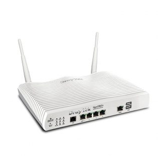
Vigor2832 series is an ADSL2/2+ router. It integrates IP layer QoS, NAT session/bandwidth management to help users control works well with large bandwidth. By adopting hardware-based VPN platform and hardware encryption of AES/DES/3DES, the router increases the performance of VPN greatly and offers several protocols (such as IPSec/PPTP/L2TP) with up to 32 VPN tunnels. -
Page 15: I-1-1 Indicators And Connectors
Before you use the Vigor router, please get acquainted with the LED indicators and connectors first. Status Explanation ACT (Activity) Blinking The router is powered on and running normally. The router is powered off. USB1~USB2 / A USB device is connected and active. Blinking The data is transmitting. - Page 16 Interface Description Factory Reset Restore the default settings. Usage: Turn on the router (ACT LED is blinking). Press the hole and keep for more than 5 seconds. When you see the ACT LED begins to blink rapidly than usual, release the button. Then the router will restart with the factory default configuration.
-
Page 17: Hardware Installation
Before starting to configure the router, you have to connect your devices correctly. Connect the cable Modem/DSL Modem/Media Converter to any WAN port of router with Ethernet cable (RJ-45). Connect one end of an Ethernet cable (RJ-45) to the LAN port of the router and the other end of the cable (RJ-45) into the Ethernet port on your computer. -
Page 18: I-2-2 Installing Usb Printer To Vigor Router
You can install a printer onto the router for sharing printing. All the PCs connected this router can print documents via the router. The example provided here is made based on Windows 7. For other Windows system, please visit www.DrayTek.com. Before using it, please follow the steps below to configure settings for connected computers (or wireless clients). - Page 19 A dialog will appear. Click Add a local printer and click Next. In this dialog, choose Create a new port. In the field of Type of port, use the drop down list to select Standard TCP/IP Port. Then, click Next. Vigor2832 Series User’s Guide...
- Page 20 In the following dialog, type 192.168.1.1 (router’s LAN IP) in the field of Hostname or IP Address and type 192.168.1.1 as the Port name. Then, click Next. Click Standard and choose Generic Network Card. Vigor2832 Series User’s Guide...
- Page 21 Now, your system will ask you to choose right name of the printer that you installed onto the router. Such step can make correct driver loaded onto your PC. When you finish the selection, click Next. Type a name for the chosen printer. Click Next. Vigor2832 Series User’s Guide...
- Page 22 10. Choose Do not share this printer and click Next. 11. Then, in the following dialog, click Finish. Vigor2832 Series User’s Guide...
- Page 23 12. The new printer has been added and displayed under Printers and Faxes. Click the new printer icon and click Printer server properties. 13. Edit the property of the new printer you have added by clicking Configure Port. Vigor2832 Series User’s Guide...
- Page 24 14. Select "LPR" on Protocol, type p1 (number 1) as Queue Name. Then click OK. Next please refer to the red rectangle for choosing the correct protocol and LPR name. Vigor2832 Series User’s Guide...
- Page 25 If please visit www.draytek.com to find out the printer list. Open Support >FAQ/Application Notes; find out the link of USB>>Printer Server and click Then, click the What types of printers are compatible with Vigor router? link.
-
Page 26: Accessing Web Page
Make sure your PC connects to the router correctly. You may either simply set up your computer to get IP dynamically from the router or set up the IP address of the computer to be the same subnet as the default IP address of Vigor router 192.168.1.1. - Page 27 Now, the Main Screen will appear. Info The home page will be different slightly in accordance with the type of the router you have. The web page can be logged out according to the chosen condition. The default setting is Auto Logout, which means the web configuration system will logout after 5 minutes without any operation.
-
Page 28: Changing Password
Please change the password for the original security of the router. Open a web browser on your PC and type http://192.168.1.1. A pop-up window will open to ask for username and password. Please type “admin/admin” as Username/Password for accessing into the web user interface with admin mode. - Page 29 Info Even the password is changed, the Username for logging onto the web user interface is still “admin”. Vigor2832 Series User’s Guide...
-
Page 30: Dashboard
Dashboard shows the connection status including System Information, IPv4 Internet Access, IPv6 Internet Access, Interface (physical connection), Security and Quick Access. Click Dashboard from the main menu on the left side of the main page. A web page with default selections will be displayed on the screen. Refer to the following figure: On the top of the Dashboard, a virtual panel (simulating the physical panel of the router) displays the physical interface connection. -
Page 31: I-5-2 Name With A Link
For detailed information about the LED display, refer to I-1-1 LED Indicators and Connectors. A name with a link (e.g., Router Name, Current Time, WAN1~4 and etc.) below means you can click it to open the configuration page for modification. Vigor2832 Series User’s Guide... -
Page 32: I-5-3 Quick Access For Common Used Menu
All the menu items can be accessed and arranged orderly on the left side of the main page for your request. However, some important and common used menu items which can be accessed in a quick way just for convenience. Look at the right side of the Dashboard. -
Page 33: I-5-4 Gui Map
Host connected physically to the router via LAN port(s) will be displayed with green circles in the field of Connected. All of the hosts (including wireless clients) displayed with Host ID, IP Address and MAC address indicates that the traffic would be transmitted through LAN port(s) and then the WAN port. The purpose is to perform the traffic monitor of the host(s). -
Page 34: I-5-5 Web Console
It is not necessary to use the telnet command via DOS prompt. The changes made by using web console have the same effects as modified through web user interface. The functions/settings modified under Web Console also can be reviewed on the web user interface. -
Page 35: I-5-6 Config Backup
There is one way to store current used settings quickly by clicking the Config Backup icon. It allows you to backup current settings as a file. Such configuration file can be restored by using System Maintenance>>Configuration Backup. Simply click the icon on the top of the main screen and a pop up dialog will appear. Click Save to store the setting. -
Page 36: I-5-8 Online Status
Such page displays the physical connection status such as LAN connection status, WAN connection status, ADSL information, and so on. Physical Connection for IPv4 Protocol Vigor2832 Series User’s Guide... - Page 37 Physical Connection for IPv6 Protocol Detailed explanation (for IPv4) is shown below: Item Description LAN Status Primary DNS-Displays the primary DNS server address for WAN interface. Secondary DNS -Displays the secondary DNS server address for WAN interface. IP Address-Displays the IP address of the LAN interface. TX Packets-Displays the total transmitted packets at the LAN interface.
-
Page 38: I-5-8-2 Virtual Wan
Item Description interface. TX Bytes - Displays the speed of transmitted octets at the LAN interface. RX Bytes - Displays the speed of received octets at the LAN interface. WAN IPv6 Status Enable – No in red means such interface is available but not enabled. -
Page 39: Quick Start Wizard
Quick Start Wizard can help you to deploy and use the router easily and quickly. Click Wizards>>Quick Start Wizards. The first screen of Quick Start Wizard is entering login password. After typing the password, please click Next. On the next page as shown below, please select the WAN interface (WAN 1 to WAN4) that you use. -
Page 40: I-6-1 For Wan1 (Adsl)
WAN1 is specified for ADSL or VDSL2 connection. vailable settings are explained as follows: Item Description Display Name Type a name to identify such WAN. VLAN Tag insertion The settings configured in this field are available for WAN1 (VDSL2)/(ADSL) and WAN2. Enable –... - Page 41 Available settings are explained as follows: Item Description Protocol / Choose PPPoE/PPPoA for WAN1 interface. Encapsulation Type in the value provided by ISP. Auto detect – Click this button to have the VPI and VCI to be detected by the system automatically Type in the value provided by ISP.
- Page 42 Available settings are explained as follows: Item Description Service Name Enter the description of the specific network service. (Optional) User Name Type in the valid user name (maximum 63 characters) provided by the ISP in this field. Password Type a valid password provided by the ISP. Confirm Password Retype the password.
- Page 43 Now, you can enjoy surfing on the Internet. Choose WAN1 as WAN Interface and click the Next button; you will get the following page. Available settings are explained as follows: Item Description Protocol There are two modes offered for you to choose for WAN1 interface.
-
Page 44: I-6-2 For Wan2 (Ethernet)
Cancel Click it to give up the quick start wizard. Please type in the IP address/mask/gateway information originally provided by your ISP. Then click Next for viewing summary of such connection. Click Finish. A page of Quick Start Wizard Setup OK!!! will appear. Then, the system status of this protocol will be shown. - Page 45 Item Description Display Name Type a name for the router. VLAN Tag insertion Enable – Enable the function of VLAN with tag. The router will add specific VLAN number to all packets on the WAN while sending them out. Please type the tag value and specify the priority for the packets sending by WAN2.
- Page 46 Available settings are explained as follows: Item Description Service Name Enter the description of the specific network service. (Optional) Username Assign a specific valid user name provided by the ISP. Note: The maximum length of the user name you can set is 63 characters.
- Page 47 Please manually enter the Username/Password provided by your ISP. Click Next for viewing summary of such connection. Click Finish. A page of Quick Start Wizard Setup OK!!! will appear. Then, the system status of this protocol will be shown. Now, you can enjoy surfing on the Internet. Vigor2832 Series User’s Guide...
- Page 48 Choose WAN2 as the WAN Interface and click the Next button. The following page will be open for you to specify Internet Access Type. Click PPTP/L2TP as the Internet Access Type. Then click Next to continue. Available settings are explained as follows: Item Description Username...
- Page 49 manually. IP Address - Type the IP address. Subnet Mask –Type the subnet mask. Gateway – Type the IP address of the gateway. Primary DNS –Type in the primary IP address for the router. Second DNS –Type in secondary IP address for necessity in the future.
- Page 50 Choose WAN2 as the WAN Interface and click the Next button. The following page will be open for you to specify Internet Access Type. Click Static IP as the Internet Access type. Simply click Next to continue. Available settings are explained as follows: Item Description WAN IP...
- Page 51 Please type in the IP address information originally provided by your ISP. Then click Next for next step. Click Finish. A page of Quick Start Wizard Setup OK!!! will appear. Then, the system status of this protocol will be shown. Now, you can enjoy surfing on the Internet.
- Page 52 Choose WAN2 as WAN Interface and click the Next button. The following page will be open for you to specify Internet Access Type. Click DHCP as the Internet Access type. Simply click Next to continue. Available settings are explained as follows: Item Description Host Name...
- Page 53 After finished the settings above, click Next for viewing summary of such connection. Click Finish. A page of Quick Start Wizard Setup OK!!! will appear. Then, the system status of this protocol will be shown. Now, you can enjoy surfing on the Internet. Vigor2832 Series User’s Guide...
-
Page 54: I-6-3 For Wan3 / Wan4 (Usb)
WAN3/WAN4 is dedicated to physical mode in USB. Choose WAN3 as WAN Interface. Then, click Next for getting the following page. Available settings are explained as follows: Item Description Internet Access Choose one of the selections as the protocol of accessing the internet. - Page 55 APN Name – APN means Access Point Name which is provided and required by some ISPs. Type the name and click Apply. 3G/4G USB Modem SIM Pin code –Type PIN code of the SIM card that will be used (DHCP mode) to access Internet.
-
Page 56: Service Activation Wizard
Service Activation Wizard is a tool which allows you to use trial version of WCF directly without accessing into the server (MyVigor) located on http://myvigor.draytek.com. For using Web Content Filter Profile, please refer to later section Web Content Filter Profile for detailed information. - Page 57 Commtouch is the web content filter based on Commtouch operated in the worldwide. There is a 30-day trial period. After trial, you can purchase DrayTek's prepared Commtouch GlobalView WCF package from retailing outlets. BPjM is WCF for German Speaking users. The fragfINN is whitelist for German Speaking users.
- Page 58 Wait for a moment till the following page appears. When such page appears, you can enable or disable these services for your necessity. Then, click Finish. Info The service will be activated and applied as the default rule configured in Firewall>>General Setup.
-
Page 59: Registering Vigor Router
You have finished the configuration of Quick Start Wizard and you can surf the Internet at any time. Now it is the time to register your Vigor router to MyVigor website for getting more service. Please follow the steps below to finish the router registration. Please login the web configuration interface of Vigor router by typing “admin/admin”... - Page 60 Info If you haven’t an accessing account, please refer to section Creating an Account for MyVigor to create your own one. Please read the articles on the Agreement regarding user rights carefully while creating a user account. The following page will be displayed after you logging in MyVigor. From this page, please click Add or Product Registration.
- Page 61 When the following page appears, please type in Nickname (for the router) and choose the right registration date from the popup calendar (it appears when you click on the box of Registration Date). After adding the basic information for the router, please click Submit.
- Page 62 This page is left blank. Vigor2832 Series User’s Guide...
-
Page 63: Part Ii Connectivity
It means wide area network. Public IP will be used in WAN. It means local area network. Private IP will be used in LAN. Local Area Network (LAN) is a group of subnets regulated and ruled by router. The design of network structure is related to what type of public IP addresses coming from your ISP. -
Page 64: Wan
It allows users to access Internet. IP means Internet Protocol. Every device in an IP-based Network including routers, print server, and host PCs, needs an IP address to identify its location on the network. To avoid address conflicts, IP addresses are publicly registered with the Network Information Centre (NIC). - Page 65 Besides, 3G/4G USB Modem in WAN3/WAN4 also can be used as backup device. Therefore, when WAN1 and WAN2 are not available, the router will use 3.5G for supporting automatically. The supported 3G/4G USB Modem will be listed on DrayTek web site. Please visit www.draytek.com for more detailed information.
-
Page 66: Web User Interface
This section will introduce some general settings of Internet and explain the connection modes for WAN1, WAN2 and WAN3/WAN4 in details. This router supports multiple-WAN function. It allows users to access Internet and combine the bandwidth of the multiple WANs to speed up the transmission through the network. Each WAN port can connect to different ISPs, Even if the ISPs use different technology to provide telecommunication service (such as DSL, Cable modem, etc.). -
Page 67: Ii-1-1-1 Wan1 (Adsl/Vdsl)
Physical Mode / Type Display the physical mode and physical type of such WAN interface. Line Speed(Kbps) Display the downstream and upstream rate of such WAN interface. DownLink/UpLink Active Mode Display whether such WAN interface is Active device or backup device. Backup (WAN#)- Display the backup WAN interface for such WAN when it is disabled. - Page 68 VLAN Tag insertion The settings configured in this field are available for ADSL. Enable – Enable the function of VLAN with tag. The router will add specific VLAN number to all packets on the WAN while sending them out. Please type the tag value and specify the priority for the packets sending by WAN1.
-
Page 69: Ii-1-1-2 Wan2 (Ethernet)
Ethernet is the Physical Mode for WAN2. Available settings are explained as follows: Item Description Enable Choose Yes to invoke the settings for this WAN interface. Choose No to disable the settings for this WAN interface. Display Name Type the description for such WAN interface. Physical Mode Display the physical mode of such WAN interface. -
Page 70: Ii-1-1-3 Wan3 / Wan4 (Usb)
automatically among all of the WAN interfaces in connection status. Active When If you choose Failover as the Active Mode, the option of Active When will appear. Any of the selected WAN disconnect – Such WAN connection will be activated when any selected WAN interface (checked below) disconnects. - Page 71 Active Mode Choose Always On to make such WAN connection being activated always. Load Balance: Check this box to enable auto load balance function for such WAN interface. When the data traffic is large, the WAN interface with the function enabled will balance the data transmission automatically among all of the WAN interfaces in connection status.
-
Page 72: Ii-1-2 Internet Access
For the router supports multi-WAN function, the users can set different WAN settings (for WAN1/WAN2/WAN3/WAN4) for Internet Access. Due to different Physical Mode for WAN interface, the Access Mode for these connections also varies. Refer to the following figures. And, And, Available settings are explained as follows: Item... - Page 73 Access Mode Use the drop down list to choose a proper access mode. The details page of that mode will be popped up. If not, click Details Page for accessing the page to configure the settings. Details Page This button will open different web page (based on IPv4) according to the access mode that you choose in WAN interface.
-
Page 74: Ii-1-2-1 Details Page For Pppoe/Pppoa In Wan1 (Physical Mode: Adsl)
Available settings are explained as follows: Item Description Enable/Disable Click Enable for activating this function. If you click Disable, this function will be closed and all the settings that you adjusted in this page will be invalid. DSL Modem Settings Set up the DSL parameters required by your ISP. - Page 75 PPPoE Pass-through The router offers PPPoE dial-up connection. Besides, you also can establish the PPPoE connection directly from local clients to your ISP via the Vigor router. When PPPoA protocol is selected, the PPPoE package transmitted by PC will be transformed into PPPoA package and sent to WAN server.
-
Page 76: Ii-1-2-2 Details Page For Mpoa In Wan1 (Physical Mode: Adsl)
for connection. If required, you can configure another account and password for ADSL connection by checking this box. If it is checked, the system will ask you to type another group of account and password additionally. PPP Authentication – Select PAP only or PAP or CHAP for PPP. - Page 77 Available settings are explained as follows: Item Description Enable/Disable Click Enable for activating this function. If you click Disable, this function will be closed and all the settings that you adjusted in this page will be invalid. DSL Modem Settings Set up the DSL parameters required by your ISP.
- Page 78 mode, you also can enable this setting to use current WAN gateway IP address for pinging. With the IP address(es) pinging, Vigor router can check if the WAN connection is on or off. TTL (Time to Live) – Set TTL value of PING operation. ...
-
Page 79: Ii-1-2-3 Details Page For Pppoe In Etherenet Wan
Enable: Check the box to specify username and password as the DHCP client identifier for some ISP. Username: Type a name as username. The maximum length of the user name you can set is 63 characters. Password: Type a password. The maximum length of the password you can set is 62 characters. - Page 80 parameters according to the information provided by your ISP. Service Name (Optional) - Enter the description of the specific network service. Username – Type in the username provided by ISP in this field. The maximum length of the user name you can set is 63 characters.
-
Page 81: Ii-1-2-4 Details Page For Static Or Dynamic Ip In Etherenet Wan
Fixed IP – Click Yes to use this function and type in a fixed IP address in the box of Fixed IP Address. Default MAC Address – You can use Default MAC Address or specify another MAC address by typing on the boxes of MAC Address for the router. - Page 82 Available settings are explained as follows: Item Description Enable / Disable Click Enable for activating this function. If you click Disable, this function will be closed and all the settings that you adjusted in this page will be invalid. Keep WAN Connection Normally, this function is designed for Dynamic IP environments because some ISPs will drop connections if there is no traffic within certain periods of time.
- Page 83 Ping Interval – Type the interval for the system to execute the PING operation. Ping Retry – Type the number of times that the system is allowed to execute the PING operation before WAN disconnection is judged. It means Max Transmit Unit for packet. RIP Protocol Routing Information Protocol is abbreviated as RIP (RFC1058)...
- Page 84 Password: Type a password. The maximum length of the password you can set is 62 characters. Specify an IP address – Click this radio button to specify some data if you want to use Static IP mode. IP Address: Type the IP address. ...
-
Page 85: Ii-1-2-5 Details Page For Pptp/L2Tp In Etherenet Wan
To use PPTP/L2TP as the accessing protocol of the internet, please click the PPTP/L2TP tab. The following web page will be shown. Available settings are explained as follows: Item Description PPTP/L2TP Enable PPTP- Click this radio button to enable a PPTP client to establish a tunnel to a DSL modem on the WAN interface. - Page 86 than the current one you are using. Fixed IP - Usually ISP dynamically assigns IP address to you each time you connect to it and request. In some case, your ISP provides service to always assign you the same IP address whenever you request.
- Page 87 3G /4G USB Modem (PPP Click Enable for activating this function. If you click Disable, mode) this function will be closed and all the settings that you adjusted in this page will be invalid. SIM PIN code Type PIN code of the SIM card that will be used to access Internet.
-
Page 88: Ii-1-2-7 Details Page For 3G/4G Usb Modem (Dhcp Mode) In Usb Wan
detection mode, you have to type Primary or Secondary IP address in this field for pinging. TTL (Time to Live) – Set TTL value of PING operation. Ping Interval – Type the interval for the system to execute the PING operation. ... -
Page 89: Ii-1-2-8 Details Page For Ipv6 - Offline In Wan1/Wan2/Wan3/Wan4
SIM PIN code Type PIN code of the SIM card that will be used to access Internet. The maximum length of the PIN code you can set is 19 characters. Network Mode Force Vigor router to connect Internet with the mode specified here. - Page 90 Available settings are explained as follows: Item Description WAN Connection Such function allows you to verify whether network Detection connection is alive or not through Ping Detect. Mode – Choose Always On or Ping Detect for the system to execute for WAN detection. Always On means no detection will be executed.
-
Page 91: Ii-1-2-10 Details Page For Ipv6 - Tspc In Wan1/Wan2/Wan3/Wan4
available for the areas such as Taiwan (hinet), the Netherlands, Australia and UK. – – Tunnel setup protocol client (TSPC) is an application which could help you to connect to IPv6 network easily. Please make sure your IPv4 WAN connection is OK and apply one free account from hexago (http://gogonet.gogo6.com/page/freenet6-account ) before you try to use TSPC for network connection. - Page 92 After finished the above settings, click OK to save the settings. – – Available settings are explained as follows: Item Description Always On Check this box to keep the network connection always. Username Type the name obtained from the broker. Please apply new account at http://www.sixxs.net/.
- Page 93 WAN Connection Such function allows you to verify whether network Detection connection is alive or not through Ping Detect. Mode – Choose Always On or Ping Detect for the system to execute for WAN detection. Ping IP/Hostname – If you choose Ping Detect as detection mode, you have to type IP address in this field for pinging.
- Page 94 – – DHCPv6 client mode would use DHCPv6 protocol to obtain IPv6 address from server. Available settings are explained as follows: Item Description Identify Association Choose Prefix Delegation or Non-temporary Address as the identify association. IAID Type a number as IAID. WAN Connection Such function allows you to verify whether network Detection...
- Page 95 – – This type allows you to setup static IPv6 address for WAN interface. Available settings are explained as follows: Item Description Static IPv6 Address IPv6 Address – Type the IPv6 Static IP Address. Configuration Prefix Length – Type the fixed value for prefix length. Add –...
- Page 96 WAN Connection Such function allows you to verify whether network Detection connection is alive or not through Ping Detect. Mode – Choose Always On or Ping Detect or NS Detect for the system to execute for WAN detection. Always On means no detection will be executed.
- Page 97 6in4 IPv6 Address Type the static IPv6 address for IPv4 tunnel with the value for prefix length. LAN Routed Prefix Type the static IPv6 address for LAN routing with the value for prefix length. Tunnel TTL Type the number for the data lifetime in tunnel. WAN Connection Such function allows you to verify whether network Detection...
- Page 98 – – This type allows you to setup 6rd for WAN interface. Available settings are explained as follows: Item Description 6rd Mode Auto 6rd – Retrieve 6rd prefix automatically from 6rd service provider. The IPv4 WAN must be set as "DHCP". Static 6rd - Set 6rd options manually.
- Page 99 Vigor2832 Series User’s Guide...
- Page 100 This router allows you to create multi-PVC for different data transferring for using. Simply go to WAN and select Multi-PVC/VLAN page. The system allows you to set up to eight channels which are ready for choosing as the first PVC line that will be used as multi-PVC. Available settings are explained as follows: Item Description...
- Page 101 Click any index (8~10) to get the following web page: Available settings are explained as follows: Item Description Multi-VLAN Channel 8~10 Enable – Click it to enable the configuration of this channel. Disable –Click it to disable the configuration of this channel. WAN Type The connections and interfaces created in every channel may select a specific WAN type to be built upon.
- Page 102 WAN links for Channel 5, 6 and 7 are provided for router-borne application such as TR-069. The settings must be applied and obtained from your ISP. For your special request, please contact with your ISP and then click WAN link of Channel 5, 6 or 7 to configure your router. Available settings are explained as follows: Item Description...
- Page 103 two options. VLAN Tag – Type the value as the VLAN ID number. Valid settings are in the range from 1 to 4095. The network traffic flowing on each channel will be identified by the system via their VLAN Tags. Channels using the same WAN type may not configure the same VLAN tag value.
- Page 104 parameters according to the information provided by your ISP. ISP Name – Type in the name of your ISP. Username – Type in the username provided by ISP in this field. The maximum length of the name you can set is 80 characters.
- Page 105 Available settings are explained as follows: Item Description QoS Type Select a proper QoS type for the channel according to the information that your ISP provides. It represents Peak Cell Rate. The default setting is “0”. It represents Sustainable Cell Rate. The value of SCR must be smaller than PCR.
- Page 106 This function is used to determine the data traffic volume for each WAN interface respectively to prevent from overcharges for data transmission by the ISP. Please note that the Quota Limit and Billing cycle day of month settings will need to be configured correctly first in order for some period calculations to be performed correctly.
- Page 107 running out. Monthly Some ISP might apply for the network limitation based on the traffic limit per month. This setting is to offer a mechanism of resetting the traffic record every month. Data quota resets on day … – You can determine the starting day in one month.
- Page 108 Administrator is selected. Or, the system will send out SMS message to the administrator if Send SMS messages to Administrator is selected. Vigor2832 Series User’s Guide...
- Page 109 Due to the shortage of IPv4 address, more and more countries use IPv6 to solve the problem. However, to continually use the original rich resources of IPv4, both IPv6 and IPv4 networks shall communicate for each other via intercommunication mechanism to complete the shifting job from IPv4 to IPv6 gradually.
- Page 110 Info Only one WAN interface support IPv6 service at one time. In this example, WAN2 is chosen as the one supporting IPv6 service. In the following figure, use the drop down list to choose a proper connection type. Different connection types will bring out different configuration page. Refer to the following: ...
- Page 111 Access into the setting page for IPv6 service, it is not necessary for you to configure anything. Click OK and open Online Status. If the connection is successful, you will get the IP address for IPv4 and IPv6 at the same time. Vigor2832 Series User’s Guide...
- Page 112 Vigor2832 Series User’s Guide...
- Page 113 TSPC – Tunnel application, both IPv6 hosts communicate through IPv4 network Choose TSPC and type the information for TSPC service. Info While using such mode, you have to make sure the IPv4 network connection is normal. (In the following figure, the TSPC information is obtained from http://gogo6.com/ after applied for the service.) Click OK and open Online Status.
- Page 114 AICCU – Tunnel application Choose AICCU and type the information for AICCU of IPv6. Info While using such mode, you have to make sure the IPv4 network connection is normal. (In the following figure, the AICCU information is obtained from https://www.sixxs.net/main/ after applied for the service.) Click OK and open Online Status.
- Page 115 DHCPv6 Client Choose DHCPv6 Client. Click one of the identity associations and type the IAID number. Click OK and open Online Status. If the connection is successful, the physical connection will be shows as follows: Vigor2832 Series User’s Guide...
- Page 116 Static IPv6 Choose Static IPv6. Type IPv6 address, Prefix Length and Gateway Address. Click OK and open Online Status. If the connection is successful, the physical connection will be shows as follows: Vigor2832 Series User’s Guide...
- Page 117 6in4 Static Tunnel Choose 6in4 Static Tunnel. Type remote endpoint IPv4 address, 6in4 IPv6 Address, LAN Routed Prefix and Tunnel TTL. Click OK and open Online Status. If the connection is successful, the physical connection will be shows as follows: Vigor2832 Series User’s Guide...
- Page 118 Choose 6rd. Type IPv4 Border Relay, IPv4 Mask Length, 6rd Prefix and 6rd Prefix Length. Click OK and open Online Status. If the connection is successful, the physical connection will be shows as follows: Vigor2832 Series User’s Guide...
- Page 119 After finished the WAN settings for IPv6, please configure the LAN settings to make the router’s client get the IPv6 address. Access into the web user interface of Vigor2832. Open LAN>> General Setup. Click the IPv6 button. In the field of DHCPv6 Server Configuration, when DHCPv6 service is enabled, you can assign available IPv6 address for the client manually.
- Page 120 Make sure you have obtained the correct IPv6 IP address. Get into MS-DOS interface and type the command of “ipconfig”. Refer to the following figure. From the above figure we can see IPv6 IP address has been captured by the system. Use the Ping command to ping any IPv6 address indicating an IPv6 website.
- Page 121 Connect to the website for IPv6. Open a web browser and type an URL of IPv6, e.g., www.kame.net. If your computer accesses into the website by using IPv6 address, you may see a turtle dancing on the screen. If not, only a steady turtle will be seen. If you can see a turtle dancing on the screen, that means IPv6 service is ready for you to access and utilize.
- Page 122 Local Area Network (LAN) is a group of subnets regulated and ruled by router. The design of network structure is related to what type of public IP addresses coming from your ISP. The most generic function of Vigor router is NAT. It creates a private subnet of your own. As mentioned previously, the router will talk to other public hosts on the Internet by using public IP address and talking to local hosts by using its private IP address.
- Page 123 Vigor router will exchange routing information with neighboring routers using the RIP to accomplish IP routing. This allows users to change the information of the router such as IP address and the routers will automatically inform for each other. When you have several subnets in your LAN, sometimes a more effective and quicker way for connection is the Static routes function rather than other method.
- Page 124 This page provides you the general settings for LAN. Click LAN to open the LAN settings page and choose General Setup. There are several subnets provided by the router which allow users to divide groups into different subnets (LAN1 – LAN6). In addition, different subnets can link for each other by configuring Inter-LAN Routing.
- Page 125 Enable/Disable – Enable/Disable the function of DHCP Option. Each DHCP option is composed by an option number with data. For example, Option number:100 Data: abcd When such function is enabled, the specified values for DHCP option will be seen in DHCP reply packets. Interface –...
- Page 126 – – There are two configuration pages for LAN1, Ethernet TCP/IP and DHCP Setup (based on IPv4) and IPv6 Setup. Click the tab for each type and refer to the following explanations for detailed information. Available settings are explained as follows: Item Description Network Configuration...
- Page 127 to forward the DHCP request to the DHCP server. Start IP Address - Enter a value of the IP address pool for the DHCP server to start with when issuing IP addresses. If the 1st IP address of your router is 192.168.1.1, the starting IP address must be 192.168.1.2 or greater, but smaller than 192.168.1.254.
- Page 128 When you finish the configuration, please click OK to save and exit this page. – – There are two configuration pages for each LAN port, Ethernet TCP/IP and DHCP Setup (based on IPv4) and IPv6 Setup. Click the tab for each type and refer to the following explanations for detailed information.
- Page 129 Delete – Click it to remove an existed entry. Unique Local Address Such feature is used for the host without assigned IPv6 (ULA) configuration address to obtain IPv6 address automatically or have an IPv6 address specified manually via ULA configuration. It is convenient for communication among different subnets.
- Page 130 Router Advertisement Configuration – Click Enable to enable router advertisement server. The router advertisement daemon sends Router Advertisement messages, specified by RFC 2461, to a local Ethernet LAN periodically and when requested by a node sending a Router Solicitation message. These messages are required for IPv6 stateless auto-configuration.
- Page 131 Available settings are explained as follows: Item Description Network Configuration Enable/Disable - Click Enable to enable such configuration; click Disable to disable such configuration. For NAT Usage - Click this radio button to invoke NAT function. For Routing Usage - Click this radio button to invoke this function.
- Page 132 192.168.1.254. IP Pool Counts - Enter the maximum number of PCs that you want the DHCP server to assign IP addresses to. The default is 50 and the maximum is 253. Gateway IP Address - Enter a value of the gateway IP address for the DHCP server.
- Page 133 size of the network. (Default: 255.255.255.0/ 24) RIP Protocol Control, Disable - deactivate the RIP protocol. It will lead to a stoppage of the exchange of routing information between routers. (Default) Enable – activate the RIP protocol. DHCP Server DHCP stands for Dynamic Host Configuration Protocol. The Configuration router by factory default acts a DHCP server for your network so it automatically dispatch related IP settings to any local...
- Page 134 With the 6-port Gigabit switch on the LAN side, Vigor router provides extremely high speed connectivity for the highest speed local data transfer of any server or local PCs. On the Wireless-equipped models (e.g., Vigor2832n), each of the wireless SSIDs can also be grouped within one of the VLANs.
- Page 135 Enable Click it to enable VLAN configuration. P1 – P4 – Check the LAN port(s) to group them under the selected VLAN. Wireless LAN SSID1 – SSID4 – Check the SSID boxes to group them under the selected VLAN. Subnet Choose one of them to make the selected VLAN mapping to the specified subnet only.
- Page 136 Click OK. Open LAN>>General Setup. If you want to let the clients in both groups communicate with each other, simply activate Inter-LAN Routing by checking the box between LAN1 and LAN2. Vigor router supports up to six private IP subnets on LAN. Each can be independent (isolated) or common (able to communicate with each other).
- Page 137 Available settings are explained as follows: Item Description Enable Click this radio button to invoke this function. However, IP/MAC which is not listed in IP Bind List also can connect to Internet. Disable Click this radio button to disable this function. All the settings on this page will be invalid.
- Page 138 It allows you to add the one you choose from the ARP table or the IP/MAC address typed in Add and Edit to the table of IP Bind List. Update It allows you to edit and modify the selected IP address and MAC address that you create before.
- Page 139 LAN port mirror can be applied for the users in LAN. Generally speaking, this function copies traffic from one or more specific ports to a target port. This mechanism helps manager track the network errors or abnormal packets transmission without interrupting the flow of data access the network.
- Page 140 Available settings are explained as follows: Item Description Enable Check the box to enable LAN 802.1x function. Authentication Type Use the drop down list to choose which server (External RADIUS or Local 802.1x) will be used for authenticating LAN user. 802.1x ports After enabling the function, simply specify the LAN port(s) to apply such function.
- Page 141 This page allows you to configure a profile with specified URL for accessing into or display a message when a wireless/LAN user connects to Internet through this router. No matter what the purpose of the wireless/LAN client is, he/she will be forced into the URL configured here while trying to access into the Internet or the desired web page through this router.
- Page 142 To configure the profile, click any index number link to open the following page. Available settings are explained as follows: Item Description Enable Check the box to enable this function. Title Such information will be shown on the top of the browser. Body Two types can be specified for web portal setup.
- Page 143 Notice Content given in this field will be displayed on the screen when a web page is redirected by web portal mechanism. Position on Screen – The content of notice and the defined button can be shown upside (Top) or downside (Bottom) the text defined for message body.
- Page 144 Usually, the router serves as an NAT (Network Address Translation) router. NAT is a mechanism that one or more private IP addresses can be mapped into a single public one. Public IP address is usually assigned by your ISP, for which you may get charged. Private IP addresses are recognized only among internal hosts.
- Page 145 Port Redirection is usually set up for server related service inside the local network (LAN), such as web servers, FTP servers, E-mail servers etc. Most of the case, you need a public IP address for each server and this public IP address/domain name are recognized by all users. Since the server is actually located inside the LAN, the network well protected by NAT of the router, and identified by its private IP address/port, the goal of Port Redirection function is to forward all access request with public IP address from external users to the mapping...
- Page 146 Each item is explained as follows: Item Description Index Display the number of the profile. Service Name Display the description of the specific network service. WAN Interface Display the WAN IP address used by the profile. Protocol Display the transport layer protocol (TCP or UDP). Public Port Display the port number which will be redirected to the specified Private IP and Port of the internal host.
- Page 147 Mode Two options (Single and Range) are provided here for you to choose. To set a range for the specific service, select Range. In Range mode, if the public port (start port and end port) and the starting IP of private IP had been entered, the system will calculate and display the ending IP of private IP automatically.
- Page 148 As mentioned above, Port Redirection can redirect incoming TCP/UDP or other traffic on particular ports to the specific private IP address/port of host in the LAN. However, other IP protocols, for example Protocols 50 (ESP) and 51 (AH), do not travel on a fixed port. Vigor router provides a facility DMZ Host that maps ALL unsolicited data on any protocol to a single host in the LAN.
- Page 149 Choose Private IP or Active True IP first. Active True IP selection is available for WAN1 only. Private IP Enter the private IP address of the DMZ host, or click Choose PC to select one. Choose IP Click this button and then a window will automatically pop up, as depicted below.
- Page 150 Item Description Enable Check to enable the DMZ Host function. Private IP Enter the private IP address of the DMZ host, or click Choose PC to select one. Choose IP Click this button and then a window will automatically pop up, as depicted below.
- Page 151 Open Ports allows you to open a range of ports for the traffic of special applications. Common application of Open Ports includes P2P application (e.g., BT, KaZaA, Gnutella, WinMX, eMule and others), Internet Camera etc. Ensure that you keep the application involved up-to-date to avoid falling victim to any security exploits.
- Page 152 Available settings are explained as follows: Item Description Enable Open Ports Check to enable this entry. Comment Make a name for the defined network application/service. WAN Interface Specify the WAN interface that will be used for this entry. WAN IP Specify the WAN IP address that will be used for this entry.
- Page 153 After finishing all the settings here, please click OK to save the configuration. Port Triggering is a variation of open ports function. The key difference between "open port" and "port triggering" is: Once the OK button is clicked and the configuration has taken effect, "open port" keeps ...
- Page 154 Available settings are explained as follows: Item Description Comment Display the text which memorizes the application of this rule. Triggering Protocol Display the protocol of the triggering packets. Triggering Port Display the port of the triggering packets. Incoming Protocol Display the protocol for the incoming data of such triggering profile.
- Page 155 incoming packets will use the selected protocol. Select the protocol (TCP, UDP or TCP/UDP) for the incoming data of such triggering profile. Incoming Port Type the port or port range for the incoming packets. After finishing all the settings here, please click OK to save the configuration. Vigor2832 Series User’s Guide...
- Page 156 The ISP often provides you with a dynamic IP address when you connect to the Internet via your ISP. It means that the public IP address assigned to your router changes each time you access the Internet. The Dynamic DNS feature lets you assign a domain name to a dynamic WAN IP address.
- Page 157 The UPnP (Universal Plug and Play) protocol is supported to bring to network connected devices the ease of installation and configuration which is already available for directly connected PC peripherals with the existing Windows 'Plug and Play' system. For NAT routers, the major feature of UPnP on the router is “NAT Traversal”.
- Page 158 Assume you have a registered domain name from the DDNS provider, say hostname.dyndns.org, and an account with username: test and password: test. Open Applications>>Dynamic DNS. Check Enable Dynamic DNS Setup. Available settings are explained as follows: Item Description Enable Dynamic DNS Check this box to enable DDNS function.
- Page 159 The following two blocks should be typed your account Login Name: test and Password: test. Available settings are explained as follows: Item Description Enable Dynamic DNS Check this box to enable the current account. If you did Account check the box, you will see a check mark appeared on the Active column of the previous web page in step 2).
- Page 160 There are two methods offered for you to choose: WAN IP - If it is selected and the WAN IP of Vigor router is private, DDNS update will take place right away. Internet IP – If it is selected and the WAN IP of Vigor ...
- Page 161 The LAN DNS lets the network administrators host servers with privacy and security. When the network administrators of your office set up FTP, Mail or Web server inside LAN, you can specify specific private IP address (es) to correspondent servers. Thus, even the remote PC is adopting public DNS as the DNS server, the LAN DNS resolution on Vigor2832 Series will respond the specified private IP address.
- Page 162 Index Click the number below Index to access into the setting page. Profile Display the name of the LAN DNS profile. Domain Name Display the domain name of the LAN DNS profile. Forwarding Display that such profile is conditional DNS forwarding or not.
- Page 163 IP addresses mapping with the same domain name. Add – Click it to open a dialog to type the host’s IP address. Only responds to the DNS…. – Different LAN PCs can share the same domain name. However, you have to check this box to make the router identify &...
- Page 164 DNS security is able to ensure that the incoming data is not falsified and the source of the data is secure and correct to prevent from DNS attack by someone. All of WAN interfaces of Vigor router can be configured with DNS Security enabled respectively.
- Page 165 This page is used to configure settings for manually detecting if the domain is secure not. Available settings are explained as follows: Item Description Domain Type the domain name or IP address (IPv4/IPv6) that you want to query. Interface Specify the interface required for executing diagnose. DNS Server Type the IP address of the DNS Server which will diagnose the domain specified above.
- Page 166 The Vigor router has a built-in clock which can update itself manually or automatically by means of Network Time Protocols (NTP). As a result, you can not only schedule the router to dialup to the Internet at a specified time, but also restrict Internet access to certain hours so that users can connect to the Internet only during certain hours, say, business hours.
- Page 167 Available settings are explained as follows: Item Description Enable Schedule Check to enable the schedule. Setup Start Date Specify the starting date of the schedule. (yyyy-mm-dd) Start Time (hh:mm) Specify the starting time of the schedule. Duration Time Specify the duration (or period) for the schedule. (hh:mm) Action Specify which action Call Schedule should apply during the...
- Page 168 Mon - Sun 9:00 am 6:00 pm Make sure the PPPoE connection and Time Setup is working properly. Configure the PPPoE always on from 9:00 to 18:00 for whole week. Configure the Force Down from 18:00 to next day 9:00 for whole week. Assign these two profiles to the PPPoE Internet access profile.
- Page 169 Shared Secret The RADIUS server and client share a secret that is used to authenticate the messages sent between them. Both sides must be configured to use the same shared secret. The maximum length of the shared secret you can set is 36 characters.
- Page 170 secret. Enable - Check to enable RADIUS client feature. Shared Secret - The RADIUS server and client share a secret that is used to authenticate the messages sent between them. Both sides must be configured to use the same shared secret.
- Page 171 Available settings are explained as follows: Item Description Enable Check to enable TACACS+ feature. Server IP Address Enter the IP address of TACACS+ server. Destination Port The UDP port number that the TACACS+ server is using. Shared Secret The TACACS+ server and client share a secret that is used to authenticate the messages sent between them.
- Page 172 Lightweight Directory Access Protocol (LDAP) is a communication protocol for using in TCP/IP network. It defines the methods to access distributing directory server by clients, work on directory and share the information in the directory by clients. The LDAP standard is established by the work team of Internet Engineering Task Force (IETF).
- Page 173 Available settings are explained as follows: Item Description Enable Check to enable such function. Bind Type There are three types of bind type supported. Simple Mode – Just simply do the bind authentication without any search action. Anonymous – Perform a search action first with ...
- Page 174 Available settings are explained as follows: Item Description Name Type a name for such profile. The length of the user name is limited to 19 characters. Common Name Identifier Type or edit the common name identifier for the LDAP server. The common name identifier for most LDAP server is “cn”.
- Page 175 The UPnP (Universal Plug and Play) protocol is supported to bring to network connected devices the ease of installation and configuration which is already available for directly connected PC peripherals with the existing Windows 'Plug and Play' system. For NAT routers, the major feature of UPnP on the router is “NAT Traversal”.
- Page 176 IGMP is the abbreviation of Internet Group Management Protocol. It is a communication protocol which is mainly used for managing the membership of Internet Protocol multicast groups. Available settings are explained as follows: Item Description IGMP Proxy Check this box to enable this function. The application of multicast will be executed through WAN/PVC/VLAN port.
- Page 177 A PC client on LAN can be woken up by the router it connects. When a user wants to wake up a specified PC through the router, he/she must type correct MAC address of the specified PC on this web page of Wake on LAN (WOL) of this router. In addition, such PC must have installed a network card supporting WOL function.
- Page 178 The function of SMS (Short Message Service)/Mail Alert is that Vigor router sends a message to user’s mobile or e-mail box through specified service provider to assist the user knowing the real-time abnormal situations. Vigor router allows you to set up to 10 SMS profiles which will be sent out according to different conditions.
- Page 179 Available settings are explained as follows: Item Description Index Check the box to enable such profile. Mail Service Use the drop down list to choose mail service object. All of the available objects are created in Object Settings>>SMS/Mail Service Option. If there is no object listed, click Mail Service link to define a new one with specified service provider.
- Page 180 Bonjour is a service discovery protocol which is a built-in service in Mac OS X; for Windows or Linux platform, there is correspondent software to enable this function for free. Usually, users have to configure the router or personal computers to use above services. Sometimes, the configuration (e.g., IP settings, port number) is complicated and not easy to complete.
- Page 181 2. Open the web browse, Firefox. If Bonjour and DNSSD have been installed, you can open the web page (DNSSD) and see the following results. 3. Open System Maintenance>>Management. Type a name as the Router Name and click 4. Next, open Applications>>Bonjour. Check the service that you want to use via Bonjour. 5.
- Page 182 6. Now, any page or document can be printed out through Vigor router (installed with a printer). Vigor2832 Series User’s Guide...
- Page 183 For simplifying the configuration of LDAP authentication for User Access Management, we implement “Group” feature. There is no need to pre-configure user profile for each user on Vigor router anymore. We only need to configure the Groups DN, then the Vigor router (e.g., Vigor2832 series) can pass the authentication to LDAP server with the pre-defined Group path.
- Page 184 Click OK to save the settings above. Open User Management>>General Setup. Select User-Based as the Mode option. Vigor2832 Series User’s Guide...
- Page 185 Then open VPN and Remote Access>>PPP General Setup to check the profile(s) that will be authenticated with LDAP server. After above configurations, users belong to either “rd1” or “shrd” group can access Internet after inputting their credentials on LDAP server. Vigor2832 Series User’s Guide...
- Page 186 Other routing Specify routing policy to determine the direction of the data transmission. Info For more detailed information about using policy route, refer to Support >>FAQ/Application Notes on www.draytek.com. Vigor2832 Series User’s Guide...
- Page 187 Go to LAN to open setting page and choose Static Route. The router offers IPv4 and IPv6 for you to configure the static route. Both protocols bring different web pages. Available settings are explained as follows: Item Description Index The number (1 to 30) under Index allows you to open next page to set up static route.
- Page 188 Here is an example (based on IPv4) of setting Static Route in Main Router so that user A and B locating in different subnet can talk to each other via the router. Assuming the Internet access has been configured and the router works properly: ...
- Page 189 Click the LAN >> Static Route and click on the Index Number 1. Check the Enable box. Please add a static route as shown below, which regulates all packets destined to 192.168.10.0 will be forwarded to 192.168.1.2. Click OK. Available settings are explained as follows: Item Description Enable...
- Page 190 You can set up to 40 profiles for IPv6 static route. Click the IPv6 tab to open the following page: Available settings are explained as follows: Item Description Index The number (1 to 40) under Index allows you to open next page to set up static route.
- Page 191 Available settings are explained as follows: Item Description Index Click the number of index to access into the configuration web page. Enable Check this box to enable this policy. Protocol Display the protocol used for this policy. Interface Display the interface to send packets to once the policy is matched.
- Page 192 Available settings are explained as follows: Item Description Source IP Any – Any IP can be treated as the source IP. Src IP Start - Type the source IP start for the specified WAN interface. Src IP End - Type the source IP end for the specified WAN interface.
- Page 193 4. After specifying the interface, click Next to get the following page. Available settings are explained as follows: Item Description Force NAT /Force It determines which mechanism that the router will use to Routing forward the packet to WAN. 5. After choosing the mechanism, click Next to get the summary page for reference. 6.
- Page 194 To use Advance Mode, do the following steps: 1. Click the Advance Mode radio button. 2. Click Index 2 to access into the following page. Available settings are explained as follows: Item Description Enable Check this box to enable this policy. Protocol Use the drop-down menu to choose a proper protocol for the WAN interface.
- Page 195 Destination IP Any – Any IP can be treated as the destination IP. Dest IP Start- Type the destination IP start for the specified WAN interface. Dest IP End - Type the destination IP end for the specified WAN interface. If this field is blank, it means that all the destination IPs will be passed through the WAN interface.
- Page 196 Available settings are explained as follows: Item Description Mode Analyze how a packet will be sent – Choose such mode to make Vigor router analyze how a single packet will be sent by a route policy. Analyze how multiple packets… - Choose such mode to make Vigor router analyze how multiple packets in a specified file will be sent by a route policy.
- Page 197 Analyze – Click it to perform the job of analyzing. The analyzed result will be shown on the page. If required, click export analysis to export the result as a file. Note that the analysis was based on the current "load-balance/route policy"...
- Page 198 The web user interface will be revised later. Example 1: In the following figure, a LAN to LAN VPN tunnel is built between DrayTek VPN router (e.g., Vigor2832 Series) and the remote router. Firewall Router can receive all of the traffic coming from remote PC which wants to access into Internet;...
- Page 199 Click any Index number link (e.g., 1 in this case). Configure the settings as follows. Now, if you want such route policy will be applied by Vigor router with higher priority, please adjust the value of Priority for such route policy. In general, default route is specified with the lowest priority for it value is fixed as “250”.
- Page 200 Example 2: Below shows a scenario that local users behind Vigor router A want to access into a remote service (e.g., YouTube) which is blocked or restricted by local Service Provider in area with restrictions. A policy route can be created by the side of Router A to break through the Internet censorship circumvention.
- Page 201 Address Mapping is used to map a specified private IP or a range of private IPs of NAT subnet into a specified WAN IP (or WAN IP alias IP). Refer to the following figure. Suppose the WAN settings for a router are configured as follows: WAN1: 202.211.100.10, WAN1 alias: 202.211.100.11 WAN2: 203.98.200.10 Without address mapping feature, when a NAT host with an IP say "192.168.1.10"...
- Page 202 Click the Details Page of WAN 1 to open the following page. From the above figure, set main WAN IP address as 202.211.100.10. Click the WAN IP Alias button to configure the other IP address which is 202.211.100.11. Make sure Join IP NAT Pool is not checked. Click OK to save the settings. Vigor2832 Series User’s Guide...
- Page 203 After finished configuration for WAN1, open Load-Balance/Route Policy. Click Index number 1 and 2 to configure the details. After finished the settings, click OK to save the settings respectively. Vigor2832 Series User’s Guide...
- Page 204 Upon completing the above configuration, you have specified the outgoing IP address(es) for some specific computers. Now, you bind some specific computers to some WAN IP alias for outgoing traffic. Vigor2832 Series User’s Guide...
- Page 205 The following figure shows a simple application of load balance. WAN1 and WAN2 can be used to access into Internet. The PC in LAN1 can send the data to the remote PC through the specified WAN1. Access into web user interface of Vigor2832 Series. Open Load-Balance/Route Policy>>General Setup.
- Page 206 In the following page, check Enable; set Dest IP Start and Dest IP End with 203.65.1.35 and 203.65.1.35; choose WAN1 as the Interface; click default gateway. After finished the above settings, click OK to save the configuration. Now, the packets sent to the remote PC (IP address: 203.65.1.35) will be forced to pass through WAN1.
- Page 207 Wireless LAN enables high mobility so WLAN users can simultaneously access all LAN facilities just like on a wired LAN as well as Internet access. Vigor2832 Series User’s Guide...
- Page 208 This function is used for “n” models only. Over recent years, the market for wireless communications has enjoyed tremendous growth. Wireless technology now reaches or is capable of reaching virtually every location on the surface of the earth. Hundreds of millions of people exchange information every day via wireless communication products.
- Page 209 Vigor Router is equipped with a hardware AES encryption engine so it can apply the highest protection to your data without influencing user experience. To ensure the security and privacy of your wireless communication, we provide several prevailing standards on market. WEP (Wired Equivalent Privacy) is a legacy method to encrypt each frame transmitted via radio using either a 64-bit or 128-bit key.
- Page 210 WPS (Wi-Fi Protected Setup) provides easy procedure to make network connection between wireless station and wireless access point (vigor router) with the encryption of WPA and WPA2. Vigor2832 Series User’s Guide...
- Page 211 Item Description Name Type the SSID name of this router for wireless 2.4GHz. The default name is defined with DrayTek. Change the name if required. Mode At present, the router can connect to 11b Only, 11n Only, 11g Only, Mixed (11b+11g), Mixed (11g+11n), and Mixed (11b+11g+11n) stations simultaneously.
- Page 212 determine for you. Security Key The wireless mode offered by this wizard is WPA2/PSK. The WPA encrypts each frame transmitted from the radio using the key, which either PSK (Pre-Shared Key) entered manually in this field below or automatically negotiated via 802.1x authentication.
- Page 213 Next Click it to get into the next setting page. Cancel Exit the wireless wizard without saving any changes. 4. After typing the required information, click Next. 5. The following page will display the configuration summary for wireless setting. 6. Click Finish to complete the wireless settings configuration. Vigor2832 Series User’s Guide...
- Page 214 By clicking the Wireless LAN>> General Settings, a new web page will appear so that you could configure the SSID and the wireless channel. Please refer to the following figure for more information. Available settings are explained as follows: Item Description Enable Wireless LAN Check the box to enable wireless function.
- Page 215 text numbers or various special characters. Isolate Member –Check this box to make the wireless clients (stations) with the same SSID not accessing for each other. VPN – Check this box to make the wireless clients (stations) with different VPN not accessing for each other. Schedule Set the wireless LAN to work at certain time interval only.
- Page 216 This page allows you to set security with different modes for SSID 1, 2, 3 and 4 respectively. After configuring the correct settings, please click OK to save and invoke it. The password (PSK) of default security mode is provided and stated on the label pasted on the bottom of the router.
- Page 217 simultaneously if 802.1x mode is selected. Disable - Turn off the encryption mechanism. WEP-Accepts only WEP clients and the encryption key should be entered in WEP Key. WEP/802.1x Only - Accepts only WEP clients and the encryption key is obtained dynamically from RADIUS server with 802.1X protocol.
- Page 218 In the Access Control, the router may restrict wireless access to certain wireless clients only by locking their MAC address into a black or white list. The user may block wireless clients by inserting their MAC addresses into a black list, or only let them be able to connect by inserting their MAC addresses into a white list.
- Page 219 Cancel Give up the access control set up. Click it to save the access control list. Clear All Clean all entries in the MAC address list. After finishing all the settings here, please click OK to save the configuration. WPS (Wi-Fi Protected Setup) provides easy procedure to make network connection between wireless station and wireless access point (vigor router) with the encryption of WPA and WPA2.
- Page 220 On the side of Vigor 3220 series which served as an AP, press WPS button once on the front panel of the router or click Start PBC on web configuration interface. On the side of a station with network card installed, press Start PBC button of network card.
- Page 221 Below shows Wireless LAN>>WPS web page: Available settings are explained as follows: Item Description Enable WPS Check this box to enable WPS setting. WPS Status Display related system information for WPS. If the wireless security (encryption) function of the router is properly configured, you can see ‘Configured’...
- Page 222 WDS means Wireless Distribution System. It is a protocol for connecting two access points (AP) wirelessly. Usually, it can be used for the following application: Provide bridge traffic between two LANs through the air. Extend the coverage range of a WLAN. To meet the above requirement, two WDS modes are implemented in Vigor router.
- Page 223 Click WDS from Wireless LAN menu. The following page will be shown. Available settings are explained as follows: Item Description Mode Choose the mode for WDS setting. Disable mode will not invoke any WDS setting. Bridge mode is designed to fulfill the first type of application.
- Page 224 WEP or Pre-shared key field valid or not. Choose one of the types for the router. Pre-shared Key Type – There are some types for you to choose. WPA and WPA2 are used for WDS devices (e.g.2920n wireless router, you can set the encryption mode as WPA or WPA2 to establish your WDS system between AP and the router.
- Page 225 This page allows users to set advanced settings such as operation mode, channel bandwidth, guard interval, and aggregation MSDU for wireless data transmission. Available settings are explained as follows: Item Description Operation Mode Mixed Mode – the router can transmit data with the ways supported in both 802.11a/b/g and 802.11n standards.
- Page 226 use Long Preamble if needed to communicate with this kind of devices. Tx Power Set the power percentage for transmission signal of access point. The greater the value is, the higher intensity of the signal will be. WMM Capable To apply WMM parameters for wireless data transmission, please click the Enable radio button.
- Page 227 The downstream or upstream from FTP, HTTP or some P2P applications will occupy large of bandwidth and affect the applications for other programs. Please use Bandwidth Management to make the bandwidth usage more efficient. Available settings are explained as follows: Item Description SSID...
- Page 228 Vigor router can scan all regulatory channels and find working APs in the neighborhood. Based on the scanning result, users will know which channel is clean for usage. Also, it can be used to facilitate finding an AP for a WDS link. Notice that during the scanning process (about 5 seconds), no client is allowed to connect to Vigor.
- Page 229 Station List provides the knowledge of connecting wireless clients now along with its status code. There is a code summary below for explanation. For convenient Access Control, you can select a WLAN station and click Add to Access Control below. Available settings are explained as follows: Item Description...
- Page 230 This page is left blank. Vigor2832 Series User’s Guide...
- Page 231 A Virtual Private Network (VPN) is the extension of a private network that encompasses links across shared or public networks like the Internet. In short, by VPN technology, you can send data between two computers across a shared or public network in a manner that emulates the properties of a point-to-point private link.
- Page 232 A Virtual Private Network (VPN) is the extension of a private network that encompasses links across shared or public networks like the Internet. In short, by VPN technology, you can send data between two computers across a shared or public network in a manner that emulates the properties of a point-to-point private link.
- Page 233 Such wizard is used to configure VPN settings for VPN client. Such wizard will guide to set the LAN-to-LAN profile for VPN dial out connection (from server to client) step by step. Open Wizards>>VPN Client Wizard. The following page will appear. Available settings are explained as follows: Item Description...
- Page 234 When you finish the mode and profile selection, please click Next to open the following page. In this page, you have to select suitable VPN type for the VPN client profile. There are six types provided here. Different type will lead to different configuration page. After making the choices for the client profile, please click Next.
- Page 235 When you choose IPsec, you will see the following graphic: When you choose L2TP, you will see the following graphic: Vigor2832 Series User’s Guide...
- Page 236 When you choose L2TP over IPsec (Nice to Have) or L2TP over IPsec (Must), you will see the following graphic: When you choose SSL, you will see the following graphic: Available settings are explained as follows: Item Description Profile Name Type a name for such profile.
- Page 237 for this profile. This setting is useful for dial-out only. WAN1 First/ WAN2 First /WAN3 First/WAN4 First- While connecting, the router will use WAN1/WAN2/WAN3/WAN4/WAN5 as the first channel for VPN connection. If WAN1/WAN2/WAN3/WAN4 fails, the router will use another WAN interface instead. WAN1 Only /WAN2 Only/WAN3 Only/WAN4 Only - While connecting, the router will use WAN1/WAN2/WAN3/WAN4 as the only channel for VPN connection.
- Page 238 After finishing the configuration, please click Next. The confirmation page will be shown as follows. If there is no problem, you can click one of the radio buttons listed on the page and click Finish to execute the next action. Available settings are explained as follows: Item Description...
- Page 239 Such wizard is used to configure VPN settings for VPN server. Such wizard will guide to set the LAN-to-LAN profile for VPN dial in connection (from client to server) step by step. Open Wizards>>VPN Server Wizard. The following page will appear. Available settings are explained as follows: Item Description...
- Page 240 Different Dial-in Type will lead to different configuration page. In addition, adjustable items for each dial-in type will be changed according to the VPN Server Mode (Site to Site VPN and Remote Dial-in User) selected. After making the choices for the server profile, please click Next. You will see different configurations based on the selection you made.
- Page 241 When you check PPTP & IPsec & L2TP (three types) or PPTP & IPsec (two types) or L2TP with Policy (Nice to Have/Must), you will see the following graphic: Available settings are explained as follows: Item Description Profile Name Type a name for such profile. The length of the file is limited to 10 characters.
- Page 242 Remote Network Please type the network mask (according to the real location Mask of the remote host) for building VPN connection. After finishing the configuration, please click Next. The confirmation page will be shown as follows. If there is no problem, you can click one of the radio buttons listed on the page and click Finish to execute the next action.
- Page 243 Enable the necessary VPN service as you need. If you intend to run a VPN server inside your LAN, you should disable the VPN service of Vigor Router to allow VPN tunnel pass through, as well as the appropriate NAT settings, such as DMZ or open port. After finishing all the settings here, please click OK to save the configuration.
- Page 244 This submenu only applies to PPP-related VPN connections, such as PPTP, L2TP, L2TP over IPsec. Available settings are explained as follows: Item Description Dial-In PPP Authentication PAP Only - elect this option to force the router to authenticate dial-in users with the PAP protocol. PAP/CHAP/MS-CHAP/MS-CHAPv2 - Selecting this option means the router will attempt to authenticate dial-in users with the CHAP protocol first.
- Page 245 this function when your peer router requires mutual authentication. You should further specify the User Name and Password of the mutual authentication peer. The length of the name/password is limited to 23/19 characters. Assigned IP Start Enter a start IP address for the dial-in PPP connection. You should choose an IP address from the local private network.
- Page 246 In IPsec General Setup, there are two major parts of configuration. There are two phases of IPsec. Phase 1: negotiation of IKE parameters including encryption, hash, Diffie-Hellman parameter values, and lifetime to protect the following IKE exchange, authentication of both peers using either a Pre-Shared Key or Digital Signature (x.509).
- Page 247 Key. Certificate for Dial-in –Choose one of the local certificates from the drop down list. Pre-Shared Key- Specify a key for IKE authentication. Confirm Pre-Shared Key- Retype the characters to confirm the pre-shared key. Note: Any packets from the remote dial-in user which does not match the rule defined in VPN and Remote Access>>Remote Dial-In User will be applied with the method specified here.
- Page 248 Name Display the profile name of that index. Click each index to edit one peer digital certificate. There are three security levels of digital signature authentication: Fill each necessary field to authenticate the remote peer. The following explanation will guide you to fill all the necessary fields. Available settings are explained as follows: Item Description...
- Page 249 You can manage remote access by maintaining a table of remote user profile, so that users can be authenticated to dial-in via VPN connection. You may set parameters including specified connection peer ID, connection type (VPN connection - including PPTP, IPsec Tunnel, and L2TP by itself or over IPsec) and corresponding security methods, etc.
- Page 250 Click each index to edit one remote user profile. Each Dial-In Type requires you to fill the different corresponding fields on the right. If the fields gray out, it means you may leave it untouched. The following explanation will guide you to fill all the necessary fields. Available settings are explained as follows: Item Description...
- Page 251 Specify Remote Node -You can specify the IP address of the remote dial-in user, ISDN number or peer ID (used in IKE aggressive mode). Uncheck the checkbox means the connection type you select above will apply the authentication methods and security methods in the general settings.
- Page 252 Triple DES (3DES), and AES. Local ID (Optional)- Specify a local ID to be used for Dial-in setting in the LAN-to-LAN Profile setup. This item is optional and can be used only in IKE aggressive mode. After finishing all the settings here, please click OK to save the configuration. Here you can manage LAN-to-LAN connections by maintaining a table of connection profiles.
- Page 253 If there is no profile joined yet, this page will be shown as follows: Available settings are explained as follows: Item Description View All – Click it to display the LAN to LAN profiles. Trunk – Click it to display the Trunk profiles. Set to Factory Default Click to clear all indexes.
- Page 254 Available settings are explained as follows: Item Description Common Settings Profile Name – Specify a name for the profile of the LAN-to-LAN connection. Enable this profile - Check here to activate this profile. VPN Dial-Out Through - Use the drop down menu to choose a proper WAN interface for this profile.
- Page 255 abnormal IPsec VPN connection disruption. It will help to provide the state of a VPN connection for router’s judgment of redial. Normally, if any one of VPN peers wants to disconnect the connection, it should follow a serial of packet exchange procedure to inform each other.
- Page 256 First or Subject Name First) to be used for Dial-in setting in the LAN-to-LAN Profile setup. This item is optional and can be used only in IKE aggressive mode. Local Certificate – Select one of the profiles set in Certificate Management>>Local Certificate.
- Page 257 IKE phase 1 key lifetime-For security reason, the lifetime of key should be defined. The default value is 28800 seconds. You may specify a value in between 900 and 86400 seconds. IKE phase 2 key lifetime-For security reason, the lifetime of key should be defined.
- Page 258 the User Name and Password of remote dial-in user below. IPsec Tunnel- Allow the remote dial-in user to trigger an IPsec VPN connection through Internet. L2TP with IPsec Policy - Allow the remote dial-in user to make a L2TP VPN connection through the Internet. You can select to use L2TP alone or with IPsec.
- Page 259 Subject Name First – The subject name (configured in Certificate Management>>Local Certificate) will be inspected first. IPsec Security Method - This group of fields is a must for IPsec Tunnels and L2TP with IPsec Policy when you specify the remote node. Medium- Authentication Header (AH) means data will ...
- Page 260 through the VPN connection. This is usually used when you find there are several subnets behind the remote VPN router. RIP Direction - The option specifies the direction of RIP (Routing Information Protocol) packets. You can enable/disable one of direction here. Herein, we provide four options: TX/RX Both, TX Only, RX Only, and Disable.
- Page 261 Translated Type – There are two types for you to choose. Whole Subnet Specific IP Address Virtual IP Mapping – A pop up dialog will appear for you to specify the local IP address and the mapping virtual IP address.
- Page 262 VPN trunk includes four features - VPN Backup, VPN load balance, GRE over IPsec, and Binding tunnel policy. – – VPN TRUNK Management is a backup mechanism which can set multiple VPN tunnels as backup tunnel. It can assure the network connection not to be cut off due to network environment blocked by any reason.
- Page 263 Available settings are explained as follows: Item Description Backup Profile List Set to Factory Default - Click to clear all VPN TRUNK-VPN Backup mechanism profile. No – The order of VPN TRUNK-VPN Backup mechanism profile. Status - “v” means such profile is enabled; “x” means such profile is disabled.
- Page 264 Detailed information for this dialog, see later section - Advanced Load Balance and Backup. Load Balance Profile List Set to Factory Default - Click to clear all VPN TRUNK-VPN Load Balance mechanism profile. - The order of VPN TRUNK-VPN Load Balance mechanism profile.
- Page 265 General Setup Status- After choosing one of the profile listed above, please click Enable to activate this profile. If you click Disable, the selected or current used VPN TRUNK-Backup/Load Balance mechanism profile will not have any effect for VPN tunnel. Profile Name- Type a name for VPN TRUNK profile.
- Page 266 First of all, go to VPN and Remote Access>>LAN-to-LAN. Set two or more LAN-to-LAN profiles first that will be used for Member1 and Member2. If you do not set enough LAN-to-LAN profiles, you cannot operate VPN TRUNK – VPN Backup /Load Balance mechanism profile management well.
- Page 267 Later, on peer side (as VPN Client): please type 192.168.50.100 in the field of My GRE IP and type IP address of the server (192.168.50.200) in the field of Peer GRE IP. After setting profiles for load balance, you can choose any one of them and click Advance for more detailed configuration.
- Page 268 Available settings are explained as follows: Item Description Profile Name List the load balance profile name. Load Balance Algorithm Round Robin – Based on packet base, both tunnels will send the packet alternatively. Such method can reach the balance of packet transmission with fixed rate. Weighted Round Robin –...
- Page 269 configuring Binding Tunnel. Insert after – Click this radio button to adding a new binding tunnel table. Tunnel Bind Table Index- 128 Binding tunnel tables are provided by this device. Specify the number of the tunnel for such Load Balance profile. Active –...
- Page 270 To configure a successful binding tunnel, you have to: Type Binding Src IP range (Start and End) and Binding Des IP range (Start and End). Choose TCP/UDP, IGMP/ICMP or Other as Binding Protocol. Available settings are explained as follows: Item Description Profile Name List the backup profile name.
- Page 271 Member 1 will be the top priority for the system to do VPN connection. Detail Information This field will display detailed information for Environment Recovers Detection. You can find the summary table of all VPN connections. You may disconnect any VPN connection by clicking Drop button.
- Page 272 Refresh Seconds - Choose the time for refresh the dial information among 5, 10, and 30. Refresh - Click this button to refresh the whole connection status. Vigor2832 Series User’s Guide...
-
Page 273: Application Notes
Log into the web user interface of Vigor router. Open VPN and Remote Access>>LAN to LAN to create a LAN-to-LAN profile. The following settings are for a permanent VPN connection. Click any index number to open the configuration page. Type a name which is easy for identification for such profile (in this case, type VPN Server), and check the box of Enable This Profile. - Page 274 Now navigate to the next section, Dial-In Settings to check PPTP, IPsec Tunnel and L2TP boxes. Check the box of Specify Remote… and type the Peer VPN Server IP (e.g., 218.242.130.19 in this case). Press the IKE Pre-Shared Key button to set the PSK; and select Medium (AH) or High (ESP) as the security method.
- Page 275 Log into the web user interface of Vigor router. Open VPN and Remote Access>>LAN to LAN to create a LAN-to-LAN profile. The following settings are for a permanent VPN connection. Click any index number to open the configuration page. Type a name which is easy for identification for such profile (in this case, type VPN Client), and check the box of Enable This Profile.
- Page 276 Now navigate to the next section, Dial-Out Settings to select the IPsec Tunnel service and type the remote server IP/host name (e.g., 218.242.133.91, in this case). Press the IKE Pre-Shared Key button to set the PSK; and select Medium (AH) or High (ESP) as the security method.
- Page 277 Open VPN and Remote Access>>Connection Management to check the dial-in connection status (from head office). Vigor2832 Series User’s Guide...
-
Page 278: Ssl Vpn
An SSL VPN (Secure Sockets Layer virtual private network) is a form of VPN that can be used with a standard Web browser. There are two benefits that SSL VPN provides: It is not necessary for users to preinstall VPN client software for executing SSL VPN connection. -
Page 279: Web User Interface
This page determines the general configuration for SSL VPN Server and SSL Tunnel. Available settings are explained as follows: Item Description Bind to WAN Choose and check WAN interface(s) for SSL VPN tunnel. Port Such port is set for SSL VPN server. It will not affect the HTTPS Port configuration set in System Maintenance>>Management. -
Page 280: Iv-2-2 Ssl Web Proxy
SSL Web Proxy will allow the remote users to access the internal web sites over SSL. Each item is explained as follows: Item Description Name Display the name of the profile that you create. Display the URL. Active Display current status (active or inactive) of such profile. Click number link under Index filed to set detailed configuration. - Page 281 Access Method There are three modes for you to choose. Disable – The profile will be inactive. If you choose Disable, all the web proxy profile appeared under VPN remote dial-in web page will disappear. Secured Port Redirection – Such technique applies private port mapping to random WAN port.
-
Page 282: Iv-2-3 Ssl Application
It provides a secure and flexible solution for network resources, including VNC (Virtual Network Computer) /RDP (Remote Desktop Protocol), to any remote user with access to Internet and a web browser. Each item is explained as follows: Item Description Name Display the application name of the profile that you create. - Page 283 Server Application Name Type a name for such application. The length of the name is limited to 23 characters. Application There are two types offered for you to create an application profile. Virtual Network Computing (VNC) – It allows you to access and control a remote PC through VNC protocol.
-
Page 284: Iv-2-4 User Account
With SSL VPN, Vigor2832 Series let teleworkers have convenient and simple remote access to central site VPN. The teleworkers do not need to install any VPN software manually. From regular web browser, you can establish VPN connection back to your main office even in a guest network or web cafe. - Page 285 Click each index to edit one remote user profile. Available settings are explained as follows: Item Description User account and Enable this account - Check the box to enable this function. Authentication Idle Timeout- If the dial-in user is idle over the limitation of the timer, the router will drop this connection.
- Page 286 Item Description can be viewed as one pure L2TP connection. Nice to Have - Apply the IPSec policy first, if it is applicable during negotiation. Otherwise, the dial-in VPN connection becomes one pure L2TP connection. Must -Specify the IPSec policy to be definitely applied on the L2TP connection.
- Page 287 Item Description (data) will be encrypted and authenticated. You may select encryption algorithm from Data Encryption Standard (DES), Triple DES (3DES), and AES. Local ID - Specify a local ID to be used for Dial-in setting in the LAN-to-LAN Profile setup. This item is optional and can be used only in IKE aggressive mode.
-
Page 288: Iv-2-5 User Group
There are 10 user group profiles which can be created for authentication by LDAP server. Such profiles will be used by applications such as User Management, VPN and etc. Each item is explained as follows: Item Description Set to Factory Default Click to clear all indexes. - Page 289 Available settings are explained as follows: Item Description Enable Check this box to enable such profile. Group Name Type a name for such profile. The length of the name is limited to 23 characters. Access Authority Specify the authority for such profile. At present, Vigor router allows you to create SSL Web Proxy and SSL Application profiles used for SSL VPN.
-
Page 290: Iv-2-6 Online User Status
If you have finished the configuration of SSL Web Proxy (server), users can find out corresponding settings when they access into DrayTek SSL VPN portal interface. Next, users can open SSL VPN>> Online Status to view logging status of SSL VPN. -
Page 291: Certificate Management
A digital certificate works as an electronic ID, which is issued by a certification authority (CA). It contains information such as your name, a serial number, expiration dates etc., and the digital signature of the certificate-issuing authority so that a recipient can verify that the certificate is real. -
Page 292: Web User Interface
Available settings are explained as follows: Item Description Generate Click this button to open Generate Certificate Request window. Type in all the information that the window requests. Then click Generate again. Import Click this button to import a saved file as the certification information. - Page 293 Info Please be noted that “Common Name” must be configured with rotuer’s WAN IP or domain name. After clicking GENERATE, the generated information will be displayed on the window below: Vigor router allows you to generate a certificate request and submit it the CA server, then import it as “Local Certificate”.
- Page 294 Available settings are explained as follows: Item Description Upload Local Certificate It allows users to import the certificate which is generated by Vigor router and signed by CA server. If you have done well in certificate generation, the Status of the certificate will be shown as “OK”.
- Page 295 Click this button to refresh the information listed below. Click this button to view the detailed settings for certificate request. Info You have to copy the certificate request information from above window. Next, access your CA server and enter the page of certificate request, copy the information into it and submit a request.
-
Page 296: Iv-3-2 Trusted Ca Certificate
Therefore, Vigor router offers a mechanism which allows you to generate root CA to save time and provide convenience for general user. Later, such root CA generated by DrayTek server can perform the issuing of local certificate. Info Root CA can be deleted but not edited. - Page 297 Click Create to open the following page. Type in all the information that the window request such as certifcate name (used for identifying different certificate), subject alternative name type and relational settings for subject name. Then click GENERATE again. To import a pre-saved trusted CA certificate, please click IMPORT to open the following window.
-
Page 298: Iv-3-3 Certificate Backup
Local certificate and Trusted CA certificate for this router can be saved within one file. Please click Backup on the following screen to save them. If you want to set encryption password for these certificates, please type characters in both fields of Encrypt password and Confirm password. -
Page 299: Part V Security
While the broadband users demand more bandwidth for multimedia, interactive applications, or distance learning, security has been always the most concerned. The firewall of the Vigor router helps to protect your local network against attack from unauthorized outsiders. It also restricts users in the local network from accessing the Internet. - Page 300 While the broadband users demand more bandwidth for multimedia, interactive applications, or distance learning, security has been always the most concerned. The firewall of the Vigor router helps to protect your local network against attack from unauthorized outsiders. It also restricts users in the local network from accessing the Internet.
- Page 301 Stateful inspection is a firewall architecture that works at the network layer. Unlike legacy static packet filtering, which examines a packet based on the information in its header, stateful inspection builds up a state machine to track each connection traversing all interfaces of the firewall and makes sure they are valid.
-
Page 302: Web User Interface
Below shows the menu items for Firewall. General Setup allows you to adjust settings of IP Filter and common options. Here you can enable or disable the Call Filter or Data Filter. Under some circumstance, your filter set can be linked to work in a serial manner. So here you assign the Start Filter Set only. Also you can configure the Log Flag settings, Apply IP filter to VPN incoming packets, and Accept incoming fragmented UDP packets. -
Page 303: Firewall
Data Filter Check Enable to activate the Data Filter function. Assign a start filter set for the Data Filter. Accept large incoming… Some on-line games (for example: Half Life) will use lots of fragmented UDP packets to transfer game data. Instinctively as a secure firewall, Vigor router will reject these fragmented packets to prevent attack unless you enable “Accept large incoming fragmented UDP or ICMP Packets”. - Page 304 Such page allows you to choose filtering profiles including QoS, Load-Balance policy, WCF, APP Enforcement, URL Content Filter, for data transmission via Vigor router. Available settings are explained as follows: Item Description Filter Select Pass or Block for the packets that do not match with the filter rules.
- Page 305 refer to section Syslog/Mail Alert for more detailed information. URL Content Filter Select one of the URL Content Filter profile settings (created in CSM>> URL Content Filter) for applying with this router. Please set at least one profile for choosing in CSM>> URL Content Filter web page first.
- Page 306 Window size – It determines the size of TCP protocol (0~65535). The more the value is, the better the performance will be. However, if the network is not stable, small value will be proper. Session timeout – Setting timeout for sessions can make the best utilization of network resources.
-
Page 307: V-1-2 Filter Setup
Click Firewall and click Filter Setup to open the setup page. To edit or add a filter, click on the set number to edit the individual set. The following page will be shown. Each filter set contains up to 7 rules. Click on the rule number button to edit each rule. - Page 308 Service Type Display the protocol setting with source port and destination port value. Action Display the action taken when packets match the rule. Display the CSM profile name used by such rule. Move Up/Down Use Up or Down link to move the order of the filter rules. Next Filter Set Set the link to the next filter set to be executed after the current filter run.
- Page 309 Source/Destination IP Click Edit to access into the following dialog to choose the source/destination IP or IP ranges. To set the IP address manually, please choose Any Address/Single Address/Range Address/Subnet Address as the Address Type and type them in this dialog. In addition, if you want to use the IP range from defined groups or objects, please choose Group and Objects as the Address Type.
- Page 310 5. If there is no error, click Finish to complete wizard setting. To use Advance Mode, do the following steps: 1. Click the Advance Mode radio button. 2. Click one of the indexe number linke (e.g., Index 2) to access into the following page. Available settings are explained as follows: Item Description...
- Page 311 Comments Enter filter set comments/description. Maximum length is 14- character long. Index(1-15) Set PCs on LAN to work at certain time interval only. You may choose up to 4 schedules out of the 15 schedules pre-defined in Applications >> Schedule setup. The default setting of this field is blank and the function will always work.
- Page 312 To set the service type manually, please choose User defined as the Service Type and type them in this dialog. In addition, if you want to use the service type from defined groups or objects, please choose Group and Objects as the Service Type.
- Page 313 branch from the drop-down menu. Be aware that the router will apply the specified filter rule for ever and will not return to previous filter rule any more. Sessions Control The number typed here is the total sessions of the packets that do not match the filter rule configured in this page.
- Page 314 Web Content Filter Select one of the Web Content Filter profile settings (created in CSM>> Web Content Filter) for applying with this router. Please set at least one profile for anti-virus in CSM>> Web Content Filter web page first. Or choose [Create New] from the drop down list in this page to create a new profile.
- Page 315 TCP protocol only; session timeout is configured for the data flow which matched with the firewall rule. DrayTek Banner – Please uncheck this box and the following screen will not be shown for the unreachable web page. The default setting is Enabled.
-
Page 316: V-1-3 Dos Defense
As a sub-functionality of IP Filter/Firewall, there are 15 types of detect/ defense function in the DoS Defense setup. The DoS Defense functionality is disabled for default. Click Firewall and click DoS Defense to open the setup page. Available settings are explained as follows: Item Description Enable Dos Defense... - Page 317 be regarded as “attack event” and the session will be paused for 10 seconds. Enable ICMP flood defense Check the box to activate the ICMP flood defense function. Similar to the UDP flood defense function, once if the Threshold of ICMP packets from Internet has exceeded the defined value, the router will discard the ICMP echo requests coming from the Internet.
- Page 318 scan, SYN FINscan, Xmas scan and full Xmas scan. Block Tear Drop Check the box to activate the Block Tear Drop function. Many machines may crash when receiving ICMP datagrams (packets) that exceed the maximum length. To avoid this type of attack, the Vigor router is designed to be capable of discarding any fragmented ICMP packets with a length greater than 1024 octets.
- Page 319 Vigor2832 Series User’s Guide...
-
Page 320: Application Notes
We can specify certain computers (e.g., 192.168.1.10 ~ 192.168.1.20) accessing to Internet through Vigor router. Others (e.g., 192.168.1.31 and 192.168.1.32) outside the range can get the source from LAN only. The way we can use is to set two rules under Firewall. For Rule 1 of Set 2 under Firewall>>Filter Setup is used as the default setting, we have to create a new rule starting from Filter Rule 2 of Set 2. - Page 321 Check the box of Check to enable the Filter Rule. Type the comments (e.g., block_all). Choose Block If No Further Match for the Filter setting. Then, click OK. Info In default, the router will check the packets starting with Set 2, Filter Rule 2 to Filter Rule 7.
- Page 322 Check the box of Check to enable the Filter Rule. Type the comments (e.g., open_ip). Click the Edit button for Source IP. A dialog box will be popped up. Choose Range Address as Address Type by using the drop down list. Type 192.168.1.10 in the field of Start IP, and type 192.168.1.20 in the field of End IP.
- Page 323 Now, check the content of Source IP is correct or not. The action for Filter shall be set with Pass Immediately. Then, click OK to save the settings. Both filter rules have been created. Click OK. Now, all the settings are configured well. Only the computers with the IP addresses within 192.168.1.10 ~ 192.168.1.20 can access to Internet.
-
Page 324: Csm(Central Security Management)
CSM is an abbreviation of Central Security Management which is used to control IM/P2P usage, filter the web content and URL content to reach a goal of security management. As the popularity of all kinds of instant messenger application arises, communication cannot become much easier. -
Page 325: Web User Interface
You can define policy profiles for IM (Instant Messenger)/P2P (Peer to Peer)/Protocol/Misc application. This page allows you to set 32 profiles for different requirements. The APP Enforcement Profile will be applied in Default Rule of Firewall>>General Setup for filtering. Available settings are explained as follows: Item Description Set to Factory Default... - Page 326 Below shows the items which are categorized under IM. Available settings are explained as follows: Item Description Profile Name Type a name for the CSM profile. The maximum length of the name you can set is 15 characters. Select All Click it to choose all of the items in this page.
-
Page 327: V-2-2 Appe Signature Upgrade
The APPE Enforcement Profile adopted by Vigor router will be treated as the APPE signature. DrayTek will periodically upgrade versions for all of the APPs supported by Vigor router. However, it might be inconvenient for users to upgrade the APP version one by one. This feature is specially designed to offer a quick method to execute APP version upgrade. -
Page 328: V-2-3 Url Content Filter Profile
Choose File to locate the signature file which downloaded from MyVigor portal or FTP server previously. Then, click Upgrade and wait for the system completing the process. Upgrade Automatically Scheduled Update - Check the box to make Vigor router upgrading the APPE signature based on the schedule configured here. - Page 329 Each item is explained as follows: Item Description Set to Factory Default Clear all profiles. Profile Display the number of the profile which allows you to click to set different policy. Name Display the name of the URL Content Filter Profile. Administration Message You can type the message manually for your necessity.
- Page 330 Priority It determines the action that this router will apply. Both: Pass – The router will let all the packages that match with the conditions specified in URL Access Control and Web Feature below passing through. When you choose this setting, both configuration set in this page for URL Access Control and Web Feature will be inactive.
-
Page 331: V-2-4 Web Content Filter Profile
with the keywords listed on the box below. Block - Restrict accessing into the corresponding webpage with the keywords listed on the box below. If the web pages do not match with the keyword set here, it will be processed with reverse action. Exception List –... - Page 332 Please refer to section of creating MyVigor account. WCF adopts the mechanism developed and offered by certain service provider (e.g., DrayTek). No matter activating WCF feature or getting a new license for web content filter, you have to click Activate to satisfy your request.
- Page 333 Setup Test Server It is recommended for you to use the default setting, auto-selected. Find more Click it to open http://myvigor.draytek.com for searching another qualified and suitable server. Set to Factory Default Click this link to retrieve the factory settings.
- Page 334 check it by comparing the record stored. If it matches, the page will be retrieved quickly. Such item can provide URL matching with the fastest rate. L1+L2 Cache – the router will check the URL with fast processing rate combining the feature of L1 and L2. Eight profiles are provided here as Web content filters.
- Page 335 Pass - allow accessing into the corresponding webpage with the characters listed on Group/Object Selections. If the web pages do not match with the specified feature set here, they will be processed with the categories listed on the box below. Block - restrict accessing into the corresponding webpage with the characters listed on Group/Object Selections.
-
Page 336: V-2-5 Dns Filter Profile
The DNS Filter monitors DNS queries on UDP port 53 and will pass the DNS query information to the WCF to help with categorizing HTTPS URL's. DNS can be specified in LAN>>General Setup by using the server (e.g., 168.95.1.1) on router or external DNS server (e.g., 8.8.8.8). - Page 337 Syslog - The filtering result can be recorded according to the setting selected for Syslog. None – There is no log file will be recorded for this profile. Pass – Only the log about Pass will be recorded in Syslog. ...
-
Page 338: Application Notes
The website of MyVigor (a server located on http://myvigor.draytek.com) provides several useful services (such as Anti-Spam, Web Content Filter, Anti-Intrusion, and etc.) to filtering the web pages for the sake of protecting your system. To access into MyVigor for getting more information, please create an account for MyVigor. - Page 339 2. Click the Activate link. A login page for MyVigor web site will pop up automatically. 3. Click the link of Create an account now. 4. Check to confirm that you accept the Agreement and click Accept. Vigor2832 Series User’s Guide...
- Page 340 5. Type your personal information in this page and then click Continue. 6. Choose proper selection for your computer and click Continue. Vigor2832 Series User’s Guide...
- Page 341 New Account Confirmation 8. Check to see the confirmation email with the title of Letter from myvigor.draytek.com. 9. Click the Activate my Account link to enable the account that you created. The following screen will be shown to verify the register process is finished. Please click Login.
- Page 342 11. Now, click Login. Your account has been activated. You can access into MyVigor server to activate the service (e.g., WCF) that you want. 1. Access into http://myvigor.draytek.com. Find the line of Not registered yet?. Then, click the link Click here! to access into next page.
- Page 343 2. Check to confirm that you accept the Agreement and click Accept. 3. Type your personal information in this page and then click Continue. 4. Choose proper selection for your computer and click Continue. 5. Now you have created an account successfully. Click START. Vigor2832 Series User’s Guide...
- Page 344 New Account Confirmation 6. Check to see the confirmation email with the title of Letter from myvigor.draytek.com. 7. Click the Activate my Account link to enable the account that you created. The following screen will be shown to verify the register process is finished. Please click Login.
- Page 345 8. When you see the following page, please type in the account and password (that you just created) in the fields of UserName and Password. Then type the code in the box of Auth Code according to the value displayed on the right side of it. Now, click Login.
-
Page 346: How To Block Facebook Service Accessed By The Users Via Web Content Filter / Url Content Filter
There are two ways to block the facebook service, Web Content Filter and URL Content Filter. Web Content Filter, Benefits: Easily and quickly implement the category/website that you want to block. Note: License is required. URL Content Filter, Benefits: Free, flexible for customize webpage. Note: Manual setting (e.g., one keyword for one website.) Make sure the Web Content Filter (powered by Commtouch) license is valid. - Page 347 Open CSM >> Web Content Filter Profile to create a WCF profile. Check Social Networking with Action, Block. Enable this profile in Firewall>>General Setup>>Default Rule. Next time when someone accesses facebook via this router, the web page would be blocked and the following message would be displayed instead. II.
- Page 348 Open CSM>>URL Content Filter Profile. Click an index number to open the setting page. Configure the settings as the following figure. When you finished the above steps, click OK. Then, open Firewall>>General Setup. Vigor2832 Series User’s Guide...
- Page 349 Click the Default Rule tab. Choose the profile just configured from the drop down list in the field of URL Content Filter. Now, users cannot open any web page with the word “facebook” inside. B. Disallow users to play games on Facebook Open Object Settings>>Keyword Object.
- Page 350 Open CSM>>URL Content Filter Profile. Click an index number to open the setting page. Configure the settings as the following figure. When you finished the above steps, please open Firewall>>General Setup. Click the Default Rule tab. Choose the profile just configured from the drop down list in the field of URL Content Filter.
-
Page 351: Part Vi Management
There are several items offered for the Vigor router system setup: System Status, TR-069, Administrator Password, User Password, Login Page Greeting, Configuration Backup, Syslog /Mail Alert, Time and Date, Management, Reboot System, Firmware Upgrade and Activation. It is used to control the bandwith of data transmission through configuration of Sessions Limit, Bandwidth Limit, and Quality of Servie (QoS). -
Page 352: System Maintenance
For the system setup, there are several items that you have to know the way of configuration: System Status, TR-069, Administrator Password, User Password, Login Page Greeting, Configuration Backup, Syslog /Mail Alert, Time and Date, Management, Reboot System, Firmware Upgrade, Activation and Internal Service User List. Below shows the menu items for System Maintenance. -
Page 353: Web User Interface
The System Status provides basic network settings of Vigor router. It includes LAN and WAN interface information. Also, you could get the current running firmware version or firmware related information from this presentation. Available settings are explained as follows: Item Description Model Name Display the model name of the router. - Page 354 Link Status - Display current connection status. MAC Address - Display the MAC address of the WAN Interface. Connection - Display the connection type. IP Address - Display the IP address of the WAN interface. Default Gateway - Display the assigned IP address of the default gateway. IPv6 Address - Display the IPv6 address for LAN.
- Page 355 This device supports TR-069 standard. It is very convenient for an administrator to manage a TR-069 device through an Auto Configuration Server e.g., VigorACS. Available settings are explained as follows: Item Description ACS Server On Choose the interface for the router connecting to ACS server. ACS Server URL/Username/Password –...
- Page 356 Last Inform Response Time – Display the time that VigorACS server made a response while receiving Inform message from CPE last time. CPE Client Such information is useful for Auto Configuration Server. Enable/Disable – Allow/Deny the CPE Client to connect with Auto Configuration Server.
-
Page 357: Vi-1-3 Admin Setting
This page allows you to set new password for administrator. Available settings are explained as follows: Item Description Administrator Password Old Password - Type in the old password. The factory default setting for password is “admin”. New Password -Type in new password in this field. The length of the password is limited to 23 characters. - Page 358 Password – Type the password for the local user. Confirm Password – Type the password again for confirmation. Add – After typing the user name and password above, simply click it to create a new local user. The new one will be shown on the Local User List immediately.
- Page 359 This page allows you to set new password for user operation. Available settings are explained as follows: Item Description Enable User Mode for After checking this box, you can access into the web user simple web configuration interface with the password typed here for simple web configuration.
- Page 360 3. The following screen will appear. Simply click OK. 4. Log out Vigor router web user interface by clicking the Logout button. 5. The following window will be open to ask for username and password. Type the new user password in the filed of Password and click Login. Vigor2832 Series User’s Guide...
- Page 361 6. The main screen with User Mode will be shown as follows. Settings to be configured in User Mode will be less than settings in Admin Mode. Only basic configuration settings will be available in User Mode. Info Setting in User Mode can be configured as same as in Admin Mode. Vigor2832 Series User’s Guide...
- Page 362 Enable Check this box to enable the login customization function. Login Page Title Type a brief description (e.g., Welcome to DrayTek) which will be shown on the heading of the login dialog. Welcome Message and Type words or sentences here. It will be displayed for Bulletin bulletin message.
- Page 363 Vigor2832 Series User’s Guide...
- Page 364 Such function can be used to apply the router settings configured by Vigor2820/ Vigor2830/ Vigor2850 to Vigor2832. Follow the steps below to backup your configuration. Go to System Maintenance >> Configuration Backup. The following page will be popped-up, as shown below. Available settings are explained as follows: Item Description...
- Page 365 Click Save button, the configuration will download automatically to your computer as a file named config.cfg. The above example is using Windows platform for demonstrating examples. The Mac or Linux platform will appear different windows, but the backup function is still available. Info Backup for Certification must be done independently.
- Page 366 SysLog function is provided for users to monitor router. Available settings are explained as follows: Item Description SysLog Access Setup Enable - Check Enable to activate function of syslog. Syslog Save to – Check Syslog Server to save the log to Syslog server.
- Page 367 address is available or not. SMTP Server/SMTP Port - The IP address/Port number of the SMTP server. Mail To - Assign a mail address for sending mails out. Return-Path - Assign a path for receiving the mail from outside. Use SSL - Check this box to use port 465 for SMTP server for some e-mail server uses https as the transmission method.
- Page 368 From the Syslog screen, select the router you want to monitor. Be reminded that in Network Information, select the network adapter used to connect to the router. Otherwise, you won’t succeed in retrieving information from the router. Vigor2832 Series User’s Guide...
- Page 369 It allows you to specify where the time of the router should be inquired from. Available settings are explained as follows: Item Description Current System Time Click Inquire Time to get the current time. Use Browser Time Select this option to use the browser time from the remote administrator PC host as router’s system time.
- Page 370 This page allows you to configure settings for SNMP and SNMPV3 services. The SNMPv3 is more secure than SNMP through the encryption method (support AES and DES) and authentication method (support MD5 and SHA) for the management needs. Available settings are explained as follows: Item Description Enable SNMP Agent...
- Page 371 setting is public. The maximum length of the text is limited to 23 characters. Notification Host IP (IPv4) Set the IPv4 address of the host that will receive the trap community. Notification Host IP (IPv6) Set the IPv6 address of the host that will receive the trap community.
- Page 372 This page allows you to manage the settings for Internet/LAN Access Control, Access List from Internet, Management Port Setup, TLS/SSL Encryption Setup, and Device Management. The management pages for IPv4 and IPv6 protocols are different. Available settings are explained as follows: Item Description Router Name...
- Page 373 The web user interface will be open until you click the Logout icon manually. Internet Access Control Allow management from the Internet - Enable the checkbox to allow system administrators to login from the Internet. There are several servers provided by the system to allow you managing the router from Internet.
- Page 374 Available settings are explained as follows: Item Description Management Access Allow management from the Internet - Enable the checkbox Control to allow system administrators to login from the Internet. There are several servers provided by the system to allow you managing the router from Internet. Check the box(es) to specify.
- Page 375 Available settings are explained as follows: Item Description Allow management from Enable the checkbox to allow system administrators to login from LAN interface. There are several servers provided by the system which allow you to manage the router from LAN interface.
- Page 376 The Web user interface may be used to restart your router. Click Reboot System from System Maintenance to open the following page. Index (1-15) in Schedule Setup - You can type in four sets of time schedule for performing system reboot. All the schedules can be set previously in Applications >> Schedule web page and you can use the number that you have set in that web page.
- Page 377 Download the newest firmware from DrayTek's web site or FTP site. The DrayTek web site is www.DrayTek.com (or local DrayTek's web site) and FTP site is ftp.DrayTek.com. Click System Maintenance>> Firmware Upgrade to launch the Firmware Upgrade Utility. Choose the right firmware by clicking Select. Then, click Upgrade. The system will upgrade the firmware of the router automatically.
- Page 378 After you have finished the setting profiles for WCF (refer to Web Content Filter Profile), it is the time to activate the mechanism for your computer. Click System Maintenance>>Activation to open the following page for accessing http://myvigor.draytek.com. Available settings are explained as follows: Item...
- Page 379 User profiles (clients) defined and enabled in User Management>>User Profile will be displayed in this page. Such page allows you to turn on or turn off security authentication service (offered by inernal RADIUS and/or Local 802.1X) for each user profile without accessing into the User Management configuration page.
- Page 380 Uncheck the box to turn off ecurity authentication service offered by Local 802.1X server for the user profile. If you check the box next to such item, all of the user profiles listed in this page will be enabled with Local 802.1X service enabled;...
- Page 381 Sometimes network administrator does not wish end-users to change the configuration of CPE device.VigorACS (the administrator) server could use the KeepProfile Setting in the Provision page to always keep the parameter as original. This document will demonstrate how to keep the admin123 as admin password via ACS SI. 1.
- Page 382 Click on drop menu to select on the setting menu, and choose SystemMaintenance _AdminPassword Click Password parameter then drag it to left block Type admin123 in Value field Click Save button to save the setting 2. ACS server will pops up “Save Success” window. 3.
- Page 383 2. Try to modify the admin password to 123, then check whether ACS server will detect the changes and keep the original setting. 3. Wait a period of time for CPE inform. Then from the ACS log, we will find ACS has detected the parameter difference but assigned the original value again.
- Page 384 A PC with private IP address can access to the Internet via NAT router. The router will generate the records of NAT sessions for such connection. The P2P (Peer to Peer) applications (e.g., BitTorrent) always need many sessions for procession and also they will occupy over resources which might result in important accesses impacted.
- Page 385 Vigor routers as edge routers of DS domain shall check the marked DSCP value in the IP header of bypassing traffic, to allocate certain amount of resource execute appropriate policing, classification or scheduling. The core routers in the backbone will do the same checking before executing treatments in order to ensure service-level consistency throughout the whole QoS-enabled network.
- Page 386 Below shows the menu items for Bandwidth Management. In the Bandwidth Management menu, click Sessions Limit to open the web page. To activate the function of limit session, simply click Enable and set the default session limit. Available settings are explained as follows: Item Description Session Limit...
- Page 387 session. Default session limit - Defines the default session number used for each computer in LAN. Limitation List Displays a list of specific limitations that you set on this web page. Specific Limitation Start IP- Defines the start IP address for limit session. End IP - Defines the end IP address for limit session.
- Page 388 In the Bandwidth Management menu, click Bandwidth Limit to open the web page. To activate the function of limit bandwidth, simply click Enable and set the default upstream and downstream limit. Available settings are explained as follows: Item Description Bandwidth Limit Enable - Click this button to activate the function of limit bandwidth.
- Page 389 Specific Limitation Start IP - Define the start IP address for limit bandwidth. End IP - Define the end IP address for limit bandwidth. Each /Shared - Select Each to make each IP within the range of Start IP and End IP having the same speed defined in TX limit and RX limit fields;...
- Page 390 In the Bandwidth Management menu, click Quality of Service to open the web page. Available settings are explained as follows: Item Description General Setup Index – Display the WAN interface number that you can edit. Status – Display if the WAN interface is available for such function or not.
- Page 391 Item Description for VoIP SIP/RTP sent with highest priority. SIP UDP Port – Set a port number used for SIP. This page displays the QoS settings result of the WAN interface. Click the Setup link to access into next page for the general setup of WAN interface. As to class rule, simply click the Edit link to access into next for configuration.
- Page 392 When you click Setup, you can configure the bandwidth ratio for QoS of the WAN interface. There are four queues allowed for QoS control. The first three (Class 1 to Class 3) class rules can be adjusted for your necessity. Yet, the last one is reserved for the packets which are not suitable for the user-defined class rules.
- Page 393 of bandwidth. Outbound TCP ACK The difference in bandwidth between download and upload Prioritize are great in ADSL2+ environment. For the download speed might be impacted by the uploading TCP ACK, you can check this box to push ACK of upload faster to speed the network traffic.
- Page 394 For adding a new rule, click Add to open the following page. Available settings are explained as follows: Item Description Check this box to invoke these settings. Hardware Check this box to enable the hardware acceleration when Acceleration such rule is applied. Ethernet Type Please specify which protocol (IPv4 or IPv6) will be used for this rule.
- Page 395 After finishing all the settings here, please click OK to save the configuration. By the way, you can set up to 20 rules for one Class. If you want to edit an existed rule, please select the radio button of that one and click Edit to open the rule edit page for modification. To add a new service type, edit or delete an existed service type, please click the Edit link under Service Type field.
- Page 396 For adding a new service type, click Add to open the following page. Available settings are explained as follows: Item Description Service Name Type in a new service for your request. The maximum length of the name you can set is 11 characters. Service Type Choose the type (TCP, UDP or TCP/UDP or other) for the new service.
- Page 397 The QoS function is used to do bandwidth management for the services with certain IP or port number. However, there is no effect of bandwidth management on the service such as VNC or PPTV without fixed IP or port number. APP QoS employs the function of APP Enforcement to detect the types of software in application layer.
- Page 398 request. Select All Click it to select all of the protocols. Clear All Click it to de-select all of the protocols. Apply to all Choose one of the actions from the drop down list. It is prepared for applying to all protocols. Apply –...
- Page 399 Internet connection line? The advanced bandwidth management technology-QoS (Quality of Service) helps you to well allocate the bandwidth upon your demand of Voice, Video, or Data transferring. Let's see how to get the optimum bandwidth per your request by using DrayTek Vigor router as below.
- Page 400 Check the box of ACT. Click Edit to specify the local address. In the pop-up window, choose Range Address as the Address Type and type the start IP address and end IP address in relational fields. Click OK to save the settings and exit the window.
- Page 401 The class rule for VoIP has been set. Click OK to return to previous page. Do the same steps to add class rules for IPTV and Data/Email with IP addresses as shown below. Vigor2832 Series User’s Guide...
- Page 402 Assuming you get 2MB/512Kb Internet line. You can click the Setup link of WAN1 to set up the bandwidth for different groups among VoIP, IPTV and Data/Email. 10. In the Setup page, check the box of Enable the QoS Control. Type 30, 50 and 15 in the boxes for VoIP, IPTV and Data/Email respectively.
- Page 403 11. Click OK to save the settings. The class rules for WAN1 are defined as shown below. Vigor2832 Series User’s Guide...
- Page 404 Assume a teleworker sometimes works at home and takes care of children. When working time, he would use Vigor router at home to connect to the server in the headquarter office downtown via either HTTPS or V PN to check email and access internal database. Meanwhile, children may chat on Skype in the restroom.
- Page 405 Return to previous page. Enter the Name of Index Class #1 by clicking Edit link. Type the name “E-mail” for Class 1. Click OK to save the settings. Click the Setup link for WAN2. The user can set reserved bandwidth (e.g., 25%) for E-mail using protocol POP3 and SMTP.
- Page 406 Click Setup link for WAN2. Check Enable UDP Bandwidth Control on the bottom to prevent enormous UDP traffic influence other application. Click OK. Vigor2832 Series User’s Guide...
- Page 407 If the worker has connected to the headquarter using host to host VPN tunnel. (Please refer to Chapter 3 VPN for detail instruction), he may set up an index for it. Enter the Class Name of Index 3. In this index, he will set reserved bandwidth for 1 VPN tunnel. 10.
- Page 408 12. Then click Edit of Local Address to set a worker’s subnet address. Click Edit of Remote Address to set headquarter’s IP address. Leave other fields and click OK. Vigor2832 Series User’s Guide...
- Page 409 User Management is a security feature which disallows any IP traffic (except DHCP-related packets) from a particular host until that host has correctly supplied a valid username and password. Instead of managing with IP address/MAC address, User Management function manages hosts with user account. Network administrator can give different firewall policies or rules for different hosts with different User Management accounts.
- Page 410 General Setup can determine the standard (rule-based or user-based) for the users controlled by User Management. The mode (standard) selected here will influence the contents of the filter rule(s) applied to every user. Available settings are explained as follows: Item Description Mode There are two modes offered here for you to choose.
- Page 411 Authentication page Web Authentication - Choose the protocol for web authentication. Display IP Address on tracking window – Check the box to display the IP address of the client on the tracking window. Landing Page Type the information to be displayed on the first web page when the LAN user accessing into Internet via such router.
- Page 412 This page allows you to set customized profiles (up to 200) which will be applied for users controlled under User Management. Simply open User Management>>User Profile. To set the user profile, please click any index number link to open the following page. Notice that profile 1 (admin) and profile 2 (Dial-In User) are factory default settings.
- Page 413 Available settings are explained as follows: Item Description Common Settings Enable this account - Check this box to enable such user profile. Username - Type a name for such user profile (e.g., LAN_User_Group_1, WLAN_User_Group_A, WLAN_User_Group_B, etc). When a user tries to access Internet through this router, an authentication step must be performed first.
- Page 414 user. By default, the Idle Timeout is set to 10 minutes. Max User Login - Such profile can be used by many users. You can set the limitation for the number of users accessing Internet with the conditions of such profile. The default setting is 0 which means no limitation in the number of users.
- Page 415 Next, the user can access Internet through any browser on Windows. Note that Alert Tool can be downloaded from DrayTek web site. Telnet – If it is selected, the user can use Telnet command to perform the authentication job.
- Page 416 – Click this box to set and increase the data quota for such profile. – Click this box to decrease the data quota for such profile. Reset quota to default when scheduling time expired - Set default time quota and data quota for such profile. When the scheduling time is up, the router will use the default quota settings automatically.
- Page 417 This page allows you to bind several user profiles into one group. These groups will be used in Firewall>>General Setup as part of filter rules. Please click any index number link to open the following page. Default object – 1 and 2 User defined object –...
- Page 418 After finishing all the settings here, please click OK to save the configuration. This page displays the user(s) connected to the router and refreshes the connection status in an interval of several seconds. Available settings are explained as follows: Item Description Refresh Seconds Use the drop down list to choose the time interval of...
- Page 419 If a LAN client who hasn’t passed the authentication opens an external web site in his browser, he will be redirected to the router’s Web authentication interface first. Then, the client is trying to access http://www.draytek.com and but brought to the Vigor Vigor2832 Series User’s Guide...
- Page 420 router. Since this is an SSL connection, some web browsers will display warning messages. With Microsoft Internet Explorer, you may get the following warning message. Please press Continue to this website (not recommended). With Mozilla Firefox, you may get the following warning message. Select I ...
- Page 421 If the authentication is successful, the client will be redirected to the original web site that he tried to access. In this example, it is http://www.draytek.com . Furthermore, you will get a popped up window as the following. Then you can access the Internet.
- Page 422 Note, if you block the web browser to pop up any window, you will not see such window. If the authentication is failed, you will get the error message, The username or password you entered is incorrect. Please login again. In above description, you access an external web site to trigger the authentication.
- Page 423 With the default setup <body stats=1><script language='javascript'> window.location='http://www.draytek.com'</script></body>, you will be redirected to http://www.draytek.com . You may change it if you want. For example, you will get the following welcome message if you enter Login Successful in the Welcome Message table.
- Page 424 If SSL Tunnel or SSL Web Proxy is enabled in the VPN profile, the user profile in User Management will always be invalid for Web authentication. For example, if you create a user profile in User Management with chaochen/test as username/password, while a VPN Remote Dial-in user profile with the same username “chaochen”...
- Page 425 Info Here expired time is “Unlimited” means the Time Quota function is not enabled for this account. After login, this account will not be expired until it is logout. In the Web interface of router, the configuration page of Time Quota is shown as below. Vigor2832 Series User’s Guide...
- Page 426 If the Time Quota is set with “0” minute, you will get the following message which means this account has no time quota. If the Time Quota is enabled and time is not 0 minute, You will get the following message. The expired time is shown after you login. After you run out the available time, you can’t use this account any more until the administrator manually adds additional time for you.
- Page 427 The configuration of the VigorPro Alert Notice Tool is as follows: Click Authenticate Now!! to start the authentication immediately. You may get the VigorPro Alert Notice Tool from the following link: http://www.draytek.com/user/SupportDLUtility.php Info 1 Any modification to the Firewall policy will break down the connections of all current users.
- Page 428 Landing Page is a special feature configured under User Management. It can specify the message, content to be seen or specify which website to be accessed into when users try to access into the Internet by passing the authentication. Here, we take Vigor2832 Series router as an example.
- Page 429 In the following page, check the box of Landing page and click OK to save the settings. Open any browser (e.g., FireFox, Internet Explorer). The logging page will appear and asks for username and password. Please type the correct username and password. Click Login.
- Page 430 In the field of Landing Page, please type the words as below: “ <body stats=1><script language='javascript'> window.location='http://www.draytek.com'</script></body>” Next, enable the Landing Page function. Open User Management -> User Profile and click one of the index number (e.g., index number 3) links.
- Page 431 In the following page, check the box of Landing page and click OK to save the settings. Open any browser (e.g., FireFox, Internet Explorer). The logging page will appear and asks for username and password. Please type the correct username and password. Vigor2832 Series User’s Guide...
- Page 432 Click Login. If the logging is successful, you will be directed into the website of www.draytek.com. Vigor2832 Series User’s Guide...
- Page 433 When you finished the configuration, click OK to save it. Info Only DrayTek products can be detected by this function. Vigor2832 Series User’s Guide...
- Page 434 USB device connected on Vigor router can be regarded as a server or WAN interface. By way of Vigor router, clients on LAN can access, write and read data stored in USB storage disk with different applications. Vigor2832 Series User’s Guide...
- Page 435 For IPs in a range and service ports in a limited range usually will be applied in configuring router’s settings, therefore we can define them with objects and bind them with groups for using conveniently. Later, we can select that object/group that can apply it. For example, all the IPs in the same department can be defined with an IP object (a range of IP address).
- Page 436 You can set up to 192 sets of IP Objects with different conditions. Available settings are explained as follows: Item Description Set to Factory Default Clear all profiles. Index Display the profile number that you can configure. Name Display the name of the object profile. To set a new profile, please do the steps listed below: 1.
- Page 437 Available settings are explained as follows: Item Description Name Type a name for this profile. Maximum 15 characters are allowed. Interface Choose a proper interface. For example, the Direction setting in Edit Filter Rule will ask you specify IP or IP range for WAN or LAN/DMZ/RT/VPN or any IP address.
- Page 438 Subnet Mask Type the subnet mask if the Subnet Address type is selected. Invert Selection If it is checked, all the IP addresses except the ones listed above will be applied later while it is chosen. After finishing all the settings here, please click OK to save the configuration. Below is an example of IP objects settings.
- Page 439 This page allows you to bind several IP objects into one IP group. Available settings are explained as follows: Item Description Set to Factory Default Clear all profiles. Index Display the profile number that you can configure. Name Display the name of the group profile. To set a new profile, please do the steps listed below: 1.
- Page 440 Item Description Name Type a name for this profile. Maximum 15 characters are allowed. Interface Choose WAN, LAN or Any to display all the available IP objects with the specified interface. Available IP Objects All the available IP objects with the specified interface chosen above will be shown in this box.
- Page 441 To set a new profile, please do the steps listed below: 1. Click the number (e.g., #1) under Index column for configuration in details. 2. The configuration page will be shown as follows: Available settings are explained as follows: Item Description Name Type a name for this profile.
- Page 442 Prefix Length Type the number (e.g., 64) for the prefix length of IPv6 address. Invert Selection If it is checked, all the IPv6 addresses except the ones listed above will be applied later while it is chosen. After finishing all the settings, please click OK to save the configuration. This page allows you to bind several IPv6 objects into one IPv6 group.
- Page 443 Available settings are explained as follows: Item Description Name Type a name for this profile. Maximum 15 characters are allowed. Available IPv6 All the available IPv6 objects with the specified interface Objects chosen above will be shown in this box. Selected IPv6 Objects Click >>...
- Page 444 Set to Factory Default Clear all profiles. Index Display the profile number that you can configure. Name Display the name of the object profile. Vigor2832 Series User’s Guide...
- Page 445 To set a new profile, please do the steps listed below: 1. Click the number (e.g., #1) under Index column for configuration in details. 2. The configuration page will be shown as follows: Available settings are explained as follows: Item Description Name Type a name for this profile.
- Page 446 After finishing all the settings, please click OK to save the configuration. This page allows you to bind several service types into one group. Available settings are explained as follows: Item Description Set to Factory Default Clear all profiles. Index Display the profile number that you can configure.
- Page 447 To set a new profile, please do the steps listed below: 1. Click the number (e.g., #1) under Group column for configuration in details. 2. The configuration page will be shown as follows: Available settings are explained as follows: Item Description Name Type a name for this profile.
- Page 448 You can set 200 keyword object profiles for choosing as black /white list in CSM >>URL Web Content Filter Profile. Available settings are explained as follows: Item Description Set to Factory Default Clear all profiles. Index Display the profile number that you can configure. Name Display the name of the object profile.
- Page 449 To set a new profile, please do the steps listed below: 1. Click the number (e.g., #1) under Index column for configuration in details. 2. The configuration page will be shown as follows: Available settings are explained as follows: Item Description Name Type a name for this profile, e.g., game.
- Page 450 This page allows you to bind several keyword objects into one group. The keyword groups set here will be chosen as black /white list in CSM >>URL /Web Content Filter Profile. Available settings are explained as follows: Item Description Set to Factory Default Clear all profiles.
- Page 451 Name Type a name for this group. Maximum 15 characters are allowed. Available Keyword You can gather keyword objects from Keyword Object page Objects within one keyword group. All the available Keyword objects that you have created will be shown in this box. Selected Keyword Click button to add the selected Keyword objects in...
- Page 452 To set a new profile, please do the steps listed below: 1. Click the number (e.g., #1) under Profile column for configuration in details. 2. The configuration page will be shown as follows: Available settings are explained as follows: Item Description Profile Name Type a name for this profile.
- Page 453 This page allows you to set ten profiles which will be applied in Application>>SMS/Mail Alert Service. Each item is explained as follows: Item Description Set to Factory Default Clear all of the settings and return to factory default settings. Index Display the profile number that you can configure.
- Page 454 Service Provider Use the drop down list to specify the service provider which offers SMS service. Username Type a user name that the sender can use to register to selected SMS provider. The maximum length of the name you can set is 31 characters.
- Page 455 Vigor router offers several SMS service provider to offer the SMS service. However, if your service provider cannot be found from the service provider list, simply use Index 9 and Index 10 to make customized SMS service. The profile name for Index 9 and Index 10 are fixed. You can click the number (e.g., #9) under Index column for configuration in details.
- Page 456 Password Type a password that the sender can use to register to selected SMS provider. The maximum length of the password you can set is 31 characters. Quota Type the total number of the messages that the router will send out. Sending Interval Type the shortest time interval for the system to send SMS.
- Page 457 To set a new profile, please do the steps listed below: 1. Click the Mail Server tab, and click the number (e.g., #1) under Index column for configuration in details. 2. The configuration page will be shown as follows: Available settings are explained as follows: Item Description Profile Name...
- Page 458 This page allows you to set ten profiles which will be applied in Application>>SMS/Mail Alert Service. You can set an object with different monitoring situation. To set a new profile, please do the steps listed below: 1. Open Object Setting>>Notification Object, and click the number (e.g., #1) under Index column for configuration in details.
- Page 459 This page allows you to set several profiles of string object. Click Add to open the following dialog. Type the string you want and click OK. A new profile (e.g., index #1) with the defined string will be shown on the web page. In general, there is no limit in the number of string profiles created.
- Page 460 Follow the steps listed below: Log into the web user interface of Vigor router. Configure relational objects first. Open Object Settings>>SMS/Mail Server Object to get the following page. Index 1 to Index 8 allows you to choose the built-in SMS service provider. If the SMS service provider is not on the list, you can configure Index 9 and Index 10 to add the new service provider to Vigor router.
- Page 461 After finished the settings, click OK to return to previous page. Now you have finished the configuration of the SMS Provider profile setting. Open Object Settings>>Notification Object to configure the event conditions of the notification. Choose any index number (e.g., Index 1 in this case) to configure conditions for sending the SMS.
- Page 462 After finished the settings, click OK to return to previous page. You have finished the configuration of the notification object profile setting. Now, open Application >> SMS / Mail Alert Service. Use the drop down list to choose SMS Provider and the Notify Profile (specify the time of sending SMS). Then, type the phone number in the field of Recipient (the one who will receive the SMS).
- Page 463 Choose one of the Index numbers (9 or 10) allowing you to customize the SMS Provider. In the web page, type the URL string of the SMS provider and type the username and password. After clicking OK, the new added SMS provider will be added and will be available for you to specify for sending SMS out.
- Page 464 USB device connected on Vigor router can be regarded as a server or WAN interface. By way of Vigor router, clients on LAN can access, write and read data stored in USB storage disk with different applications. After setting the configuration in USB Application, you can type the IP address of the Vigor router and username/password created in USB Application>>USB User Management on the client software.
- Page 465 This page will determine the number of concurrent FTP connection, default charset for FTP server and enable SMB service. At present, the Vigor router can support USB storage disk with formats of FAT16 and FAT32 only. Therefore, before connecting the USB storage disk into the Vigor router, please make sure the memory format for the USB storage disk is FAT16 or FAT32.
- Page 466 SMB File Sharing Service Click Enable to invoke SMB file sharing service via the router. Access Mode LAN Only – Users coming from internet cannot connect to the SMB server of the router. LAN And WAN - Both LAN and WAN users can access SMB server of the router.
- Page 467 Available settings are explained as follows: Item Description FTP/SMB User Enable – Click this button to activate this profile (account) for FTP service or SMB file sharing service. Later, the user can use the username specified in this page to login into FTP server.
- Page 468 Access Rule It determines the authority for such profile. Any user, who uses such profile for accessing into USB storage disk, must follow the rule specified here. File – Check the items (Read, Write and Delete) for such profile. Directory –Check the items (List, Create and Remove) for such profile.
- Page 469 Upload Click this button to upload the selected file to the USB storage disk. The uploaded file in the USB diskette can be shared for other user through FTP. This page is to monitor the status for USB device connecting to Vigor router. In addition, the status of the USB modem or USB printer or USB sensor connecting to Vigor router can be checked from such page.
- Page 470 Such page provides the information about the brand name and model name of the USB modems which are supported by Vigor router. Vigor2832 Series User’s Guide...
- Page 471 SMB Client Support List provides the test status information for applications with file sharing operated under different platforms. Vigor2832 Series User’s Guide...
- Page 472 Files on USB storage device can be reviewed by opening USB Applicaiton>>File Explorer. If it is necessary for you to delete, copy files on the device or write, paste files to the devcie, it must be done through SMB server or FTP server. SMB service is based on the original USB FTP service.
- Page 473 Setup a user account for the FTP service by using USB Application >>USB User Management. Click index #1 link, and click Enable to enable FTP/SMB User account. Here we add a new account "user1" and assign authorities “Read”, “Write” and “List” to Click OK to save the configuration.
- Page 474 When the following screen appears, it means the FTP service is running properly. Return to USB Application >> USB Disk Status. The information for FTP server will be shown as below. Now, users in LAN of Vigor2832 can access into the USB storage device by typing ftp://192.168.1.1 on any browser.
- Page 475 This page is left blank. Vigor2832 Series User’s Guide...
- Page 476 This part will guide you to solve abnormal situations if you cannot access into the Internet after installing the router and finishing the web configuration Vigor2832 Series User’s Guide...
- Page 477 Backing to factory default setting if necessary. If all above stages are done and the router still cannot run normally, it is the time for you to contact your dealer or DrayTek technical support for advanced help. Vigor2832 Series User’s Guide...
- Page 478 Fisrt, take a look at the menu items under Diagnostics. Diagnostic Tools provide a useful way to view or diagnose the status of your Vigor router. Click Diagnostics and click Dial-out Triggering to open the web page. The internet connection (e.g., PPPoE) is triggered by a package sending from the source IP address. Available settings are explained as follows: Item Description...
- Page 479 Click Diagnostics and click Routing Table to open the web page. Available settings are explained as follows: Item Description Refresh Click it to reload the page. Vigor2832 Series User’s Guide...
- Page 480 Click Diagnostics and click ARP Cache Table to view the content of the ARP (Address Resolution Protocol) cache held in the router. The table shows a mapping between an Ethernet hardware address (MAC Address) and an IP address. Available settings are explained as follows: Item Description Refresh...
- Page 481 Available settings are explained as follows: Item Description Refresh Click it to reload the page. The facility provides information on IP address assignments. This information is helpful in diagnosing network problems, such as IP address conflicts, etc. Click Diagnostics and click DHCP Table to open the web page. Available settings are explained as follows: Item Description...
- Page 482 IP Address It displays the IP address assigned by this router for specified MAC Address It displays the MAC address for the specified PC that DHCP assigned IP address for it. Leased Time It displays the leased time of the specified PC. HOST ID It displays the host ID name of the specified PC.
- Page 483 Click Diagnostics and click DNS Cache Table to open the web page. The record of domain Name and the mapping IP address for answering the DNS query from LAN will be stored on Vigor router’s Cache temporarily and displayed on Diagnostics >> DNS Cache Table.
- Page 484 Click Diagnostics and click Ping Diagnosis to open the web page. Available settings are explained as follows: Item Description IPV4 /IPV6 Choose the interface for such function. Ping through Use the drop down list to choose the WAN interface that you want to ping through or choose Unspecified to be determined by the router automatically.
- Page 485 This page displays the running procedure for the IP address monitored and refreshes the data in an interval of several seconds. The IP address listed here is configured in Bandwidth Management. You have to enable IP bandwidth limit and IP session limit before invoking Data Flow Monitor.
- Page 486 automatically. Refresh Click this link to refresh this page manually. Index Display the number of the data flow. IP Address Display the IP address of the monitored device. TX rate (kbps) Display the transmission speed of the monitored device. RX rate (kbps) Display the receiving speed of the monitored device.
- Page 487 Click Diagnostics and click Traffic Graph to open the web page. Choose WAN1/WAN2/WAN3/WAN4 Bandwidth, Sessions, daily or weekly for viewing different traffic graph. Click Reset to zero the accumulated RX/TX (received and transmitted) data of WAN. Click Refresh to renew the graph at any time. The horizontal axis represents time.
- Page 488 Click Diagnostics and click Trace Route to open the web page. This page allows you to trace the routes from router to the host. Simply type the IP address of the host in the box and click Run. The result of route trace will be shown on the screen. Available settings are explained as follows: Item Description...
- Page 489 to ping through. Host/IP Address It indicates the IP address of the host. Trace Host/IP Address It indicates the IPv6 address of the host. Click this button to start route tracing work. Clear Click this link to remove the result on the window. Such page provides real-time syslog and displays the information on the screen.
- Page 490 This page displays the syslog recorded on the USB storage disk. Available settings are explained as follows: Item Description Time Display the time of the event occurred. Log Type Display the type of the record. Message Display the information for each event. IPv6 TSPC status web page could help you to diagnose the connection status of TSPC.
- Page 491 Such page displays authentication jobs made by Internal RADIUS or Local 802.1X. When the mouse cursor moves to the name link under User Name, the connection message (including authentication failed information) about internal RADIUS or local 802.1X service will be shown by a popped up dialog box. This page will display the complete authentication log information.
- Page 492 This page can display content of IP connection detected by DoS Flooding Defense mechanism. It is useful and convenient for network engineers (e.g., MIS engineer) to inspect the network environment to find out if there is any abnormal connection. Information of IP traced and destination port used for SYN Flood, UDP Flood and ICMP Flood attacks will be detected and shown respectively on different pages.
- Page 493 However, if an IP address is comfirmed to be blocked due to its abnormal behavior, click the Blocking IP List tab to block it forever. For example, IP address “192.168.1.123” (displayed on the following web page) will be blocked forever. Available settings are explained as follows: Item Description...
- Page 494 Follow the steps below to verify the hardware status. Check the power line and WLAN/LAN cable connections. Refer to “I-2 Hardware Installation” for details. Turn on the router. Make sure the ACT LED blink once per second and the correspondent LAN LED is bright.
- Page 495 Info The example is based on Windows 7. As to the examples for other operation systems, please refer to the similar steps or find support notes in www.DrayTek.com. Open All Programs>>Getting Started>>Control Panel. Click Network and Sharing Center. In the following window, click Change adapter settings.
- Page 496 Select Internet Protocol Version 4 (TCP/IP) and then click Properties. Select Obtain an IP address automatically and Obtain DNS server address automatically. Finally, click OK. Vigor2832 Series User’s Guide...
- Page 497 Double click on the current used Mac OS on the desktop. Open the Application folder and get into Network. On the Network screen, select Using DHCP from the drop down list of Configure IPv4. Vigor2832 Series User’s Guide...
- Page 498 The default gateway IP address of the router is 192.168.1.1. For some reason, you might need to use “ping” command to check the link status of the router. The most important thing is that the computer will receive a reply from 192.168.1.1. If not, please check the IP address of your computer.
- Page 499 Vigor2832 Series User’s Guide...
- Page 500 If the problem of LEDs cannot be solved by the above measures, please contact with the nearest reseller, or send an e-mail to DrayTek FAE for technical support. Check if the settings offered by ISP are configured well or not.
- Page 501 PIN code and try again. If it still fails, it might be the compliance problem of system. Please open DrayTek Syslog Tool to capture the connection information (WAN Log) and send the page (similar to the following graphic) to the service center of DrayTek.
- Page 502 Sometimes, a wrong connection can be improved by returning to the default settings. Try to reset the router by software or hardware. Such function is available in Admin Mode only. Info After pressing factory default setting, you will loose all settings you did before.
- Page 503 If the router still cannot work correctly after trying many efforts, please contact your dealer for further help right away. For any questions, please feel free to send e-mail to support@DrayTek.com. Vigor2832 Series User’s Guide...
- Page 504 VLAN helps you to solve these situations, and DrayTek’s products support bellow two popular types:...
- Page 505 P1 and P2 are doing NAT flow to access to the internet, but P3 and P4 will forward the packets between WAN and LAN ports directly. So far, there are two kinds of open system on Vigor router. One is DrayOS, which is DrayTek owned, and another is Linux-like which customized by DrayTek from OpenWRT. Here DrayOS system is going to be introduced to you because it is the most stable and superfast booting system in DrayTek products.
- Page 506 Vigor2832 Series User’s Guide...
- Page 507 Multi Subnet (VLAN of LAN) Vigor2832 Series User’s Guide...
- Page 508 Port-based mode Tag-based mode By above settings, there are four private networks will be created and computers attached with each of LAN ports or SSIDs which are able to obtain a private IP address from each DHCP server (LAN1/LAN2/LAN3/LAN4). However, the traffics of the LAN port or SSID that are NOT being grouped in the same VLAN are unable to forward to each other.
- Page 509 Port-based mode Tag-based mode To deploy a guest network, which serves your guests the internet accessibility, but the traffics have to be isolated from your private network due to the security considerations, it can be done by above settings. However, a switch support VLAN function is need if VLAN Tag enabled.
- Page 510 Vigor2832 Series User’s Guide...
- Page 511 Bridge mode with VLAN Set-top box (STB) or the other kinds of media devices are able to attach with Port4 or Port5 of LAN. Those devices that attached with Port4 or Port5 are able to access the services network directly which your ISP provided. Vigor2832 Series User’s Guide...
- Page 512 Vigor2832 Series User’s Guide...
- Page 513 DrayTek has been the world-leading company to integrate VPN with Vigor SOHO routers to serve professionals and business customers with secure data transactions over Internet. The facilities of VPN let businesses are able to receive and send data over Internet with secure tunnels.
- Page 514 APP to establish a SSL VPN tunnel. On VPN server, create a SSL user account. Please refer to “How to Set up SSL VPN” on www.draytek.com for detailed instructions. Download the APP from Google play, and run the APP.
- Page 515 Edit the profile. a. Enter description of this profile. b. Enter VPN Server's IP in Server. c. Enter Port as the port which VPN server uses for SSL VPN; for Vigor Routers, it is 443 by default. d. Tap SAVE to save the profile or “<” to cancel. Info Installation of relevant Root CA is required to enable server certificate authentication.
- Page 516 When the tunnel is up, the profile will turn green. Tap the bar again will disconnect the tunnel. Tap the pencil icon to edit or remove the profile. Vigor2832 Series User’s Guide...
- Page 517 This page is left blank. Vigor2832 Series User’s Guide...
- Page 518 Vigor2832 Series User’s Guide...
- Page 519 This chapter also gives you a general description for accessing telnet and describes the firmware versions for the routers explained in this manual. Info For Windows 7 user, please make sure the Windows Features of Telnet Client has been turned on under Control Panel>>Programs. Type cmd and press Enter.
- Page 520 For users using previous Windows system (e.g., 2000/XP), simply click Start >> Run and type Telnet 192.168.1.1 in the Open box as below. Next, type admin/admin for Account/Password. And, type ? to get a list of valid/common commands. Vigor2832 Series User’s Guide...
- Page 521 This command allows the user to adjust the percentage of data transmission (receiving/transmitting) for QoS application. adsl txpct [auto:percent] adsl rxpct [auto:percent] Syntax Description auto It means auto detection of ADSL transmission packet. percent It means to specify the percentage of ADSL transmission packet.
- Page 522 This command can set the Internet Access mode for the router. adsl ppp [ ? | pvc_no vci vpi Encap Proto modu acqIP idle [Username Password] Display the command syntax of “adsl ppp”. pvc_no It means the PVC number and the adjustable range is from 0 (Channel-1) to 7(Channel-8).
- Page 523 > adsl ppp o 35 8 1 1 4 1 -1 draytek draytek pvc no.=0 vci=35 vpi=8 encap=LLC(1) proto=PPPoE(1) modu=MULTI(4) AcquireIP: Dhcp_client(1) Idle timeout:-1 Username=draytek Password=draytek This command can specify a LAN port (LAN1 to LAN4) for mapping to certain PVC, and the mapping port/PVC will be operated in bridge mode.
- Page 524 ------------------------------------------------------------ Normal -1(OFF) PVC 0 & 1 can't set for bridge mode. Please use 'save' to save config. This command is useful for laboratory to measure largest power of data transmission. Please follow the steps below to set adsl drivermode. 1.
- Page 525 This command is used to test if the connection between CPE and CO is OK or not. adsl oamlb [n][type] adsl oamlb chklink [on/off] adsl oamlb [log_on/log_off] It means the total number of transmitted packets. type It means the protocol that you can use. 1 –...
- Page 526 This command can display the annex interface of this router. > adsl annex % hardware is annex B. % modem code is annex B; built at 01/15,07:34. This command is used to add or remove ADSL modes (such as ANNEXL, ANNEXM and ANNEXJ) supported by Multimode.
- Page 527 dB .1dB ts dB .1dB ts dB .1dB ts dB .1dB ts --- ----- ---- -- - --- ----- ---- -- - --- ----- ---- -- - --- ----- ---- -- --- ----- ---- -- - --- ----- ---- -- - --- ----- ---- -- - --- ----- ---- -- Bin SNR Gain Bi - Bin SNR Gain Bi - Bin SNR Gain Bi - Bin SNR Gain Bi dB .1dB ts dB .1dB ts...
- Page 528 Parameter Description status Display current status of user-defined vendor ID. Enable the user-defined function. Disable the user-defined function. set vid0 vid1 It means to set user-defined vendor ID with vid0 and vid1. The vendor ID shall be set with HEX format, ex: 00fe7244: 79612f21. >...
- Page 529 This command can configure PVC to PVC binding. Such command is available only for PPPoE and MPoA 1483 Bridge mode. adsl pvcbinding [pvc_x pvc_y | status | -1 ] Parameter Description pvc_x The PVC number for the source. pvc_y The PVC number that the source PVC will be bound to. status Display a table for PVC binding group.
- Page 530 System vendor ID : 0XB5004946544E0000 System country code : 0XB500 System provider code : IFTN System vendor info : 0X000 Version number : 3.8.2_RC4a_STD Version number(16 octets) : 0X332E382E325F524334615F5354440000 Self-test result : PASS Transmission mode capability : 0X40004004C010400 > This command allows to configure a network setting specified for Australia’s ISP. bpa m [-<command>...
- Page 531 “csm appe prof “ is used to configure the APP Enforcement Profile name. Such profile will be applied in Default Rule of Firewall>>General Setup for filtering. csm appe prof -i INDEX [-v | -n NAME|setdefault] Parameter Description INDEX Specify the index number of CSM profile, from 1 to 32. View the configuration of the CSM profile.
- Page 532 Profile 1 - : <NULL> action set to Pass. > It is used to display group (IM/P2P/Protocol and Others) information APP Enforcement Profile. csm appe show [-a|-i|-p|-t|-m] Parameter Description View the configuration status for All groups. View the configuration status of IM group. View the configuration status of P2P group.
- Page 533 > csm appe config -v 1 -m Group Type Index Name Enable vance Enable Advance abbreviation: Message, File Transfer, Game, Conference, and Other Advance abbreviation: : M, F, G, C, and O ------------------------------------------------------------------- OTHERS TUNNEL DNSCrypt Disable OTHERS TUNNEL DynaPass Disable OTHERS TUNNEL...
- Page 534 Disable notification e-mail mechanism. Send an example e-mail. > csm appe email -e Enable APPE email. It is used to configure settings for URL control filter profile. csm ucf show csm ucf setdefault csm ucf msg MSG csm ucf obj INDEX [-n PROFILE_NAME | -l [P|B|A|N] | uac | wf ] csm ucf obj INDEX -n PROFILE_NAME csm ucf obj INDEX -p VALUE csm ucf obj INDEX -l P|B|A|N...
- Page 535 Set Web Feature part. > csm ucf obj 1 -n game -l B Profile Index: 1 Profile Name:[game] Log:[none] Priority Select : [Bundle : Pass] [ ]Enable URL Access Control Action:[pass] [ ]Prevent web access from IP address. No Obj NO. Object Name --- -------- --------------------------------- No Grp NO.
- Page 536 KEY_WORD_Group_Index Specify the index number of the group profile. > csm ucf obj 1 uac -i E Profile Index: 1 Profile Name:[game] Log:[none] Priority Select : [Bundle : Pass] [ ]Enable URL Access Control Action:[pass] [v]Prevent web access from IP address. No Obj NO.
- Page 537 It means to configure the settings regarding to Web Feature (wf). csm ucf obj INDEX wf -v csm ucf obj INDEX wf -e csm ucf obj INDEX wf -d csm ucf obj INDEX wf -a P|B csm ucf obj INDEX wf -s WEB_FEATURE csm ucf obj INDEX wf -u WEB_FEATURE csm ucf obj INDEX wf -f File_Extension_Object_index Parameter...
- Page 538 File Extension Object Index : [0] Profile Name : [] [V] Cookie [ ] Proxy [ ] Upload It means to configure the settings regarding to web control filter (wcf). csm wcf show csm wcf look csm wcf cache csm wcf server WCF_SERVER csm wcf msg MSG csm wcf setdefault csm wcf obj INDEX -v...
- Page 539 KEY_WORD_Object_Index Specify the index number of the object profile. Set the keyword group. KEY_WORD_Group_Index Specify the index number of the group profile. Set the action for the black and white list. E:Enable, D:Disable, P:Pass, B:Block It means to choose the items under CATEGORY or WEB_GROUP. It means to discard items under CATEGORY or WEB_GROUP.
- Page 540 > csm wcf obj 1 -n test_wcf Profile Index: 1 Profile Name:[test_wcf] []White/Black list Action:[block] No Obj NO. Object Name --- -------- --------------------------------- No Grp NO. Group Name --- -------- --------------------------------- Action:[block] Log:[block] ------------------------------------------------------------------ child Protection Group: [v]Alcohol & Tobacco [v]Criminal &...
- Page 541 Parameter Description enable Enable or disable DNS Filter. ON: enable. OFF: disable. syslog Determine the content of records transmitting to Syslog. P: Pass. Records for the packets passing through DNS filter will be sent to Syslog. B: Block. Records for the packets blocked by DNS filter will be sent to Syslog.
- Page 542 Displays the DDNS log. >ddns log > Sets and displays the DDNS time. ddns time <update in minutes> Parameter Description Update in minutes Type the value as DDNS time. The range is from 1 to 14400. > ddns time ddns time <update in minutes> Valid: 1 ~ 14400 %Now: 14400 >...
- Page 543 Enable defense function for a specific attack(s). ATTACK_0 Specify a name of the following attacks: ip_option, tcp_flag, land, teardrop, smurf, pingofdeath, traceroute, icmp_frag, syn_frag, unknow_proto, fraggle. Disable the defense function for a specific attack(s). >dos –A The Dos Defense system is Activated >dos –s synflood 50 10 Synflood is enabled! Threshold=50 <pke/sec>...
- Page 544 n=1 ~ 999: Idle time for offline (default 180 seconds) -i <ip address> It means that PPPoE server will assign an IP address specified here for CPE (PPPoE client). If you type 0.0.0.0 as the <ip address>, ISP will assign suitable IP address for you.
- Page 545 WAN1 ISP Name set to tcom WAN1 Username set to username WAN1 Password set successful WAN1 PPP Authentication Type set to PAP/CHAP WAN1 Idle timeout set to always-on WAN1 Gateway IP set to 0.0.0.0 > internet -V WAN1 Internet Mode:PPPoE ISP Name: tcom Username: username Authentication: PAP/CHAP...
- Page 546 as the public subnet IP address. > ip pubaddr ? % ip addr <public subnet IP address> % Now: 192.168.0.1 > ip pubaddr 192.168.2.5 % Set public subnet IP address done !!! This command allows users to set the mask for IP routed subnet of your router. ip pubmask ? ip pubmask <public subnet mask>...
- Page 547 > ip aux add 192.168.1.65 1 % 192.168.1.65 has added in index 3. When you type ip aux?, the current auxiliary WAN IP Address table will be shown as the following: Index no. Status IP address IP pool ---------------------------------------------- Enable 172.16.3.229 Enable 172.16.3.56...
- Page 548 > ip nmask 255.255.0.0 % Set IP netmask OK !!! ARP displays the matching condition for IP and MAC address. ip arp add [IP address] [MAC address] [LAN or WAN] ip arp del [IP address] [LAN or WAN] ip arp flush ip arp status ip arp accept [0/1/2/3/4/5status] ip arp setCacheLife [time]...
- Page 549 This command is available for WAN DHCP. ip dhcpc option ip dhcpc option -h|l ip dhcpc option -d [idx] ip dhcpc option -e [1 or 0] -w [wan unmber] -c [option number] -v [option value] ip dhcpc option -e [1 or 0] -w [wan unmber] -c [option number] -x "[option value]" ip dhcpc option -e [1 or 0] -w [wan unmber] -c [option number] -a [option value] ip dhcpc option -u [idx unmber] ip dhcpc release [wan number]...
- Page 550 Leased Elapsed T2 : 226794 This command allows users to ping IP address of WAN1/WAN2 for verifying if the WAN connection is OK or not. ip ping [IP address] [WAN1/WAN2] Parameter Description IP address It means the WAN IP address. WAN1/WAN2 It means the WAN interface that the above IP address passes through.
- Page 551 ip telnet [IP address][Port] Parameter Description IP address Type the WAN or LAN IP address of the remote device. Port Type a port number (e.g., 23). Available settings: 0 ~65535. > ip telnet 172.17.3.252 23 > This command allows users to set the RIP (routing information protocol) of IP. ip rip [0/1/2] Parameter Description...
- Page 552 > ip wanrip ? Valid ex:ip wanrip <ifno> -e <0/1> <ifno> 1: WAN1,2: WAN2 3: PVC3,4: PVC4,5: PVC5 -e <0/1> 0: disable, 1: enable Now status: WAN[1] Rip Protocol disable WAN[2] Rip Protocol disable WAN[3] Rip Protocol disable WAN[4] Rip Protocol disable WAN[5] Rip Protocol disable >...
- Page 553 rtype It means the type of the route. default : default route; static: static route. It means current IP range for CNC Network. default Set WAN1/WAN2/off as current default route. clean Clean all of the route settings. 1: Enable the function. 0: Disable the function.
- Page 554 This command allows users to enable/disable igmp proxy server. ip igmp_proxy set ip igmp_proxy reset ip igmp_proxy wan ip igmp_proxy query ip igmp_proxy ppp [0/1] ip igmp_proxy status Parameter Description It means to enable proxy server. reset It means to disable proxy server. It means to specify WAN interface for IGMP service.
- Page 555 This command is used to enable/disable igmp snoop server. ip igmp_snoop enable ip igmp_snoop disable ip igmp_snoop status ip igmp_snoop txquery [on|off] [v2|v3] ip igmp_snoop chkleave [on|off] ip igmp_snoop separate [on|off] Parameter Description enable It means to enable proxy server. disable It means to disable proxy server.
- Page 556 > ip igmp_fl enable %% ip igmp_fl [enable|disable|status], IGMP Fast Leave is Enabled. > Specify MAC address of certain device as the DMZ host. ip dmz [mac] Parameter Description It means the MAC address of the device that you want to specify. >ip dmz ? % ip dmz <mac>, now : 00-00-00-00-00-00...
- Page 557 This command allows users to set maximum session limit number for the specified IP; set message for exceeding session limit and set how many seconds the IP session block works. ip session on ip session off ip session default [num] ip session defaultp2p [num] ip session status ip session show...
- Page 558 This command allows users to set maximum bandwidth limit number for the specified IP. ip bandwidth on ip bandwidth off ip bandwidth default [tx_rate][rx_rate] ip bandwidth status ip bandwidth show ip bandwidth [add/del] [IP1-IP2][tx][rx][shared] Parameter Description Turn on the IP bandwidth limit. Turn off the IP bandwidth limit.
- Page 559 ip bindmac show ip bindmac add [IP][MAC][Comment] ip bindmac del [IP]/all Parameter Description Turn on IP bandmac policy. Even the IP is not in the policy table, it can still access into network. Turn off all the bindmac policy. strict_on It means that only those IP address in IP bindmac policy table can access into network.
- Page 560 This command is used to set the maximum number of NAT users. ip maxnatuser user no Parameter Description User no A number specified here means the total NAT users that Vigor router supports. 0 – It means no limitation. > ip maxnatuser 100 % Max NAT user = 100 This command is used to set the IP policy route profile.
- Page 561 Any: It means any port number can be used as destination port. -G [default/specific] Specify the gateway mode. -L [default/specific] Specify the failover gateway mode. -s [value] Indicate the source IP start. Value: The type format shall be “xxx.xxx.xxx.xxx”. (e.g, 192.168.1.0) -S [value] Indicate the source IP end.
- Page 562 Value: Available settings include, 0: Disable the function of “failback”. 1: Enable the function of “failback”. -v: View current failback setting. Diagnose for Policy Route -s [value] It means “source IP”. Value: Available settings include: Any: It indicates any IP address can be used as source IP address. “xxx.xxx.xxx.xxx”: The type format (e.g, 192.168.1.0).
- Page 563 -e <0/1> 0: disable the selected LAN DNS profile. 1: enable the selected LAN DNS profile. -i <profile setting index Type the index number of the profile. number> List the content of LAN DNS profile (including domain name, IP address and message). -n <domain name>...
- Page 564 > ip dnsforward -i 1 -n ftp.drayTek.com % Configure Set1's DomainName:ftp.drayTek.com > ip dnsforward -i 1 -a 172.16.1.1 % Configure Set1's IP:172.16.1.1 > ip dnsforward -i 1 -l % Idx: 1 % State: Disable % Profile: test % Domain Name: ftp.drayTek.com % DNS Server IP: 172.16.1.1...
- Page 565 LAN|WAN1|WAN2|iface# It means to specify LAN or WAN interface for such address. [<command> The available commands with parameters are listed below. <parameter>|…] […] means that you can type in several commands in one line. It means to show current DHCPv6 status. It means to ask the SIP.
- Page 566 > ip6 dhcp client WAN2 –p 2008::1 > ip6 dhcp client WAN2 –a Interface WAN2 has following DHCPv6 client settings: DHCPv6 client enabled request IA_PD whose IAID equals to 2008 > ip6 dhcp client WAN2 –n 1023456 > ip6 dhcp client WAN2 –a Interface WAN2 has following DHCPv6 client settings: DHCPv6 client enabled request IA_NA whose IAID equals to 2008...
- Page 567 This command allows you to configure settings for accessing Internet. ip6 internet -W n -M n [-<command> <parameter> | ... ] Parameter Description -W n W means to set WAN interface and n means different selections. Default is WAN1. n=1: WAN1 n=2: WAN2 n=3: WAN3 n=X: WANx...
- Page 568 -T n Set 6in4 Tunnel TTL. n=1 to 255. (Default number is 255) For TSPC/AICCU -u [username] Set Username (max. 63 characters). -P [password] Set Password (max. 63 characters). -s [server] Set Tunnel Server IP. server= IPv4 Address or URL (max. 63 characters). For AICCU -p [prefix] Set Subnet Prefix (AICCU).
- Page 569 > ip6 internet -W 1 -M 2 -u userid -p passwd -s broker.freenet6.net This setting will take effect after rebooting. Please use "sys reboot" command to reboot the router. > This command allows you to display IPv6 neighbour table. ip6 neigh –s [inet6_addr] [eth_addr] [LAN1|LAN2|...|LAN4|WAN1|WAN2|USB1|USB2] ip6 neigh -d [inet6_addr] [LAN1|LAN2|...|LAN4|WAN1|WAN2|USB1|USB2] ip6 neigh -a [inet6_addr] [-N LAN1|LAN2|...|LAN4|WAN1|WAN2|USB1|USB2] Parameter...
- Page 570 This command allows you to add a proxy neighbour. ip6 pneigh -s inet6_addr [LAN1|LAN2|...|LAN4|WAN1|WAN2|USB1|USB2] ip6 pneigh -d inet6_addr [LAN1|LAN2|...|LAN4|WAN1|WAN2|USB1|USB2] ip6 pneigh -a [inet6_addr] [-N LAN1|LAN2|...|LAN4|WAN1|WAN2|USB1|USB2] Parameter Description It means to add a proxy neighbour. It means to delete a proxy neighbour. It means to show proxy neighbour status.
- Page 571 > ip6 route -s FE80::250:7FFF:FE12:500 16 FE80::250:7FFF:FE12:100 LAN Route FE80::250:7FFF:FE12:500/16 successfully added! > ip6 route -a LAN PREFIX/PREFIX-LEN _EXPIRES_ _NEXT-HOP_ I/F METRIC STATE FLAGS ------------------------------------------------------------------------- ------ FE80::/128 UNICAST FE80::250:7FFF:FE00:0/128 UNICAST FE80::/64 UNICAST FE80::/16 1024 UNICAST FE80::250:7FFF:FE12:100 FF02::1/128 UNICAST FF02::1 FF00::/8 UNICAST ::/0 UNREACHABLE !
- Page 572 This command allows you to trace the routes from the router to the host. ip6 tracert [IPV6 address/Host] [LAN1|LAN2|...|LAN4|WAN1|WAN2|USB1|USB2] Parameter Description IPV6 address/Host It means to specify the IPv6 address or host for ping. LAN1|LAN2|...|LAN4|WAN1 It means to specify LAN or WAN interface for such address. |WAN2|USB1|USB2 >...
- Page 573 Status: Connected > This command allows you to enable or disable RADVD server. Ip6 radvd [LAN1|LAN2|...|LAN4] [-<command> <parameter>| ... ] ip6 radvd [R|u] Parameter Description LAN1|LAN2|...|LAN4 It means to specify LAN interface for such address. <command> <parameter> It means to enable or disable the default lifetime of the RADVD server.
- Page 574 > ip6 radvd LAN1 -v % [LAN1] setting ! Status : Enable RDNSS : Enable Default Lifetime : 1800 seconds min interval time: 200 seconds MAX interval time: 600 seconds Hop limit : 64 : auto Reachable time Retransmit time : 0 Preference : Medium Prefix valid lifetime...
- Page 575 FE80::250:7FFF:FE12:1010 FE80::250:7FFF:FE12:1020 FE80::250:7FFF:FE12:2080 > ip6 mngt status % IPv6 Remote Management : telnet : off, http : off, ping : off This command allows you to check the online status of IPv6 LAN /WAN. ip6 online [WAN1|WAN2|USB1|USB2] Parameter Description WAN1|WAN2|USB1|USB2 It means the connection interface.
- Page 576 reset AICCU Retry Account OK! > This command allows you to set IPv6 settings for NTP (Network Time Protocols) server. ip6 ntp –h ip6 ntp –v ip6 ntp –p [0/1] Parameter Description –h It is used to display the usage of such command. It is used to show the NTP state.
- Page 577 n = 2: DHCPv6. -o n Enable Other option(O-bit) flag. (O-bit is redundant when management is DHCPv6) n= 0: Disable n= 1: Enable. -e n: Add an extension WAN. n = 1: WAN1 n = 2: WAN2 n = x: WANx. -E n Delete an extension WAN.
- Page 578 Running: yes Log Flags: 0x80947278 = nonip Default: pass all, Logging: available This command is used to set general rule for firewall. ipf set [Options] ipf set [SET_NO] rule [RULE_NO] [Options] Parameter Description Options There are several options provided here, such as -v, -c [SET_NO], -d [SET_NO],…...
- Page 579 -------------------------------------------------------------- CodePage : ANSI(1252)-Latin I Window size : 65535 Session timeout : 1440 DrayTek Banner : Enable --------------------------------------------------------------- Apply IP filter to VPN incoming packets : Enable Accept large incoming fragmented UDP or ICMP packets: Enable ---------------------------------------------------------------- Strict Security Checking [ ]APP Enforcement >...
- Page 580 Parameter Description Such word means Filter Set, range form 1~12. Such word means Filter Rule, range from 1~7. <Command><parameter> The following lists all of the available commands with parameters. It means to enable or disable the rule setting. 0- disable 1- enable -s o:g <obj>...
- Page 581 <obj> – indicates index number of object or index number of group. Available settings range from 1-96. For example, “-S 0 1" means the first service type object profile. -S u <protocol> It means to configure advanced settings for Service Type, such as <source_port__value>...
- Page 582 <index> – Available settings range from 0 ~ 8. “0” means no profile will be applied. log flag- 0 means disable to save and display in Syslog; 1 means enable to save and display in Syslog. -n <index> <Log Flag> It means to specify which DNS Filter profile will be applied.
- Page 583 : Enable ---------------------------------------------------------------------- CodePage : ANSI(1252)-Latin I Window size : 65535 Session timeout : 1440 DrayTek Banner : Enable --------------------------------------------------------------------- Strict Security Checking [ ]APP Enforcement > This command is used to set and view flowtrack sessions. ipf flowtrack set [-re]...
- Page 584 icmp >ipf flowtrack set -r Refresh the flowstate ok > ipf flowtrack view -f Start to show the flowtrack sessions state: ORIGIN>> 192.168.1.11:59939 -> 8.8.8.8: 53 ,ifno=0 REPLY >> 8.8.8.8: 53 -> 192.168.1.11:59939 ,ifno=3 proto=17, age=93023180(3920), flag=203 ORIGIN>> 192.168.1.11:15073 -> 8.8.8.8: 53 ,ifno=0 REPLY >>...
- Page 585 Relay agent IP = 0.0.0.0 25:36:33.580 ---->DHCP (WAN-5) Len = 548XID = 0x7880fdd4 Client IP = 0.0.0.0 Your IP = 0.0.0.0 Next server IP = 0.0.0.0 Relay agent IP = 0.0.0.0 25:36:41.580 ---->DHCP (WAN-5) Len = 548XID = 0x7880fdd4 Client IP = 0.0.0.0 Your IP = 0.0.0.0...
- Page 586 > ldap user 1 -n LD_user_test1 Profile Name has been updated! > ldap user 1 -v Profile Index:1 Profile Name:LD_user_test1 Common Name Identifier: Base Distinguished Name: Additional Filter: Group distinguished Name: >ldap user 1 -b ou=People,dc=example,dc=com This command is used to set general settings (e.g., IP address, port number) for LDAP server. ldap set [Options][Value] Parameter Description...
- Page 587 LDAP Server Port has been setting. > ldap set dn dc=example,dc=com LDAP Regular DN has been setting. > ldap set PWD 123456 LDAP Regular Password has been setting. This command is used to check current status of LDAP settings configuration. ldap view >...
- Page 588 -i [address]: client IPv4 address(domain) -m [mask]: client IPv4 mask -p [prefix]: client IPv6 prefix -l [length]: client IPv6 prefix length -s [secret]: shared secret ex: radius client add 1 -i 192.168.1.1 -m 255.255.255.0 -s 123 client [del] [idx] del - Delete related settings for selected client. Idx - Specify the index number of client profiles.
- Page 589 Please use "sys reboot" command to reboot the router. > tacacsplus view TACACS+ Enable:Enable. TACACS+ Server IP:192.168.1.59 TACACS+ Server Port:49 TACACS+ Type:ASCII TACACS+ Shared Secret: This command allows users to check the general settings for TACACS+ server tacacspluse view > tacacsplus view TACACS+ Enable:Enable.
- Page 590 This command allows users to set HTTPS port for management. mngt httpsport [Https port] Parameter Description Https port It means to type the number for HTTPS port. The default setting is 443. > mngt httpsport 443 % Set web server port to 443 done. This command allows users to set telnet port for management.
- Page 591 Parameter Description All PING packets will be forwarded from LAN PC to Internet. All PING packets will be blocked from LAN PC to Internet. viewlog It means to display a log of ping action, including source MAC and source IP. clearlog It means to clear the log of ping action.
- Page 592 This command can block specified port for passing through the router. mngt defenseworm [on] mngt defenseworm [off] mngt defenseworm [add port] mngt defenseworm [del port] mngt defenseworm [viewlog] mngt defenseworm [clearlog] Parameter Description It means to activate the function of defense worm packet out. It means to inactivate the function of defense worm packet out.
- Page 593 off – disable the function. > mngt rmtcfg ftp on Enable server fail Remote configure function has been disabled please enable by enter mngt rmtcfg enable > mngt rmtcfg enable %% Remote configure function has been enabled. > mngt rmtcfg ftp on %% FTP server has been enabled.
- Page 594 - HTTP:No - HTTPS:No - TELNET:Yes - SSH:No * Subnet: - LAN 2: disabled - LAN 3: enabled - LAN 4: disabled - LAN 5: disabled - LAN 6: disabled - DMZ: disabled - IP Routed Subnet: disabled Note: the settings do NOT apply to LAN1, LAN1 is always allowed to access the router This command allows users to reject or accept PING packets from the Internet.
- Page 595 -T <seconds> It means to set the trap timeout <0~999>. It means to list SNMP setting. > mngt snmp -e 1 -g draytek -s DK -m 192.168.1.1 -t trapcom -n 10.20.3.40 -T 88 SNMP Agent Turn on!!! Get Community set to draytek Set Community set to DK Manager Host IP set to 192.168.1.1...
- Page 596 msubnet switch [2/3/4][On/Off] Parameter Description 2/3/4/5/6 It means LAN interface. 2=LAN2 3=LAN3 4=LAN4 On/Off On means turning on the subnet for the specified LAN interface. Off means turning off the subnet. > msubnet switch 2 On % LAN2 Subnet On! This setting will take effect after rebooting.
- Page 597 4=LAN4 IP address Type the subnet mask address for the specified LAN interface. > msubnet nmask 2 255.255.0.0 % Set LAN2 subnet mask done !!! This setting will take effect after rebooting. Please use "sys reboot" command to reboot the router. This command is used to display current status of subnet.
- Page 598 This command is used to configure the subnet for NAT or Routing usage. msubnet nat [2/3/4] [On/Off] Parameter Description 2/3/4/5/6 It means LAN interface. 2=LAN2 3=LAN3 4=LAN4 On/Off On – It means the subnet will be configured for NAT usage. Off - It means the subnet will be configured for Routing usage.
- Page 599 2/3/4/5/6 It means LAN interface. 2=LAN2 3=LAN3 4=LAN4 IP counts Specify a total number of IP address allowed for each LAN interface. The available range is from 0 to 220. > msubnet ipcnt 2 15 This setting will take effect after rebooting. Please use "sys reboot"...
- Page 600 Parameter Description 2/3/4 It means LAN interface. 2=LAN2 3=LAN3 4=LAN4 Gateway IP Type an IP address as the starting IP address for a subnet. > msubnet startip 2 192.168.2.90 %Set LAN2 Dhcp Start IP done !!! This setting will take effect after rebooting. Please use "sys reboot"...
- Page 601 2=LAN2 3=LAN3 4=LAN4 count Choose the following number for specifying different node type. 1= B-node 2= P-node 4= M-node 8= H-node 0= Not specify any type for node. > msubnet nodetype ? % msubnet nodetype <2/3/4> <count> % Now: LAN2 0; LAN3 0; LAN4 0 % count: 1.
- Page 602 This command is used to configure secondary WINS server. msubnet secWINS [2/3/4] [WINS IP] Parameter Description 2/3/4 It means LAN interface. 2=LAN2 3=LAN3 4=LAN4 WINS IP Type the IP address as the WINS IP. > > msubnet secWINS 2 192.168.3.89 % Set LAN2 Dhcp Secondary WINS IP done !!! >...
- Page 603 This command is used to set TFTP server for multi-subnet. msubnet tftp [2/3/4] [TFTP server name] Parameter Description 2/3/4/5/6 It means LAN interface. 2=LAN2 3=LAN3 4=LAN4 TFTP server name Type a name to indicate the TFTP server. > msubnet tftp ? % msubnet tftp <2/3/4>...
- Page 604 fault: 1500 (Bytes) e.x: >msubnet mtu LAN1 1492 Current Settings: LAN1 MTU: 1492 (Bytes) LAN2 MTU: 1500 (Bytes) LAN3 MTU: 1500 (Bytes) LAN4 MTU: 1500 (Bytes) IP Routed Subnet MTU: 1500 (Bytes) This command is used to create an IP object profile. object ip obj setdefault object ip obj INDEX -v object ip obj INDEX -n NAME...
- Page 605 starting point and another IP address as end point. Type an IP address. [END/MASK_IP] Type an IP address (different with START_IP) as the end IP address. > object ip obj 1 -n marketing > object ip obj 1 -a 1 192.168.1.45 >...
- Page 606 Interface:[Any] Included ip object index: [0:][0] [1:][0] [2:][0] [3:][0] [4:][0] [5:][0] [6:][0] [7:][0] > object ip grp 2 -i 1 > object ip grp 2 -a 1 2 IP Group Profile 2 Name :[First] Interface:[Lan] Included ip object index: [0:][1] [1:][2] [2:][0] [3:][0]...
- Page 607 This comman is used to create an IP object profile. object ip obj setdefault object ip obj INDEX -v object ip obj INDEX -n NAME object ip obj INDEX -i INTERFACE object ip obj INDEX -s INVERT object ip obj INDEX -a TYPE [START_IP] [END/MASK_IP] Parameter Description setdefault...
- Page 608 Start ip address:[192.168.1.45] End/Mask ip address:[0.0.0.0] Invert Selection:[0] This command is used to integrate several IP objects under an IP group profile. object ip grp setdefault object ip grp INDEX -v object ip grp INDEX -n NAME object ip grp INDEX -i INTERFACE object ip grp INDEX -a IP_OBJ_INDEX Parameter Description...
- Page 609 IP Group Profile 2 Name :[First] Interface:[Lan] Included ip object index: [0:][1] [1:][2] [2:][0] [3:][0] [4:][0] [5:][0] [6:][0] [7:][0] This command is used to create service object profile. object service obj setdefault object service obj INDEX -v object service obj INDEX -n NAME object service obj INDEX -p PROTOCOL object service obj INDEX -s CHK [START_P] [END_P] object service obj INDEX -d CHK [START_P] [END_P]...
- Page 610 available for this service type. 2=larger(>), the port number greater than this value is available.. 3=less(<), the port number less than this value is available for this profile. -s CHK [START_P] [END_P] It means to set souce port check and configure port range (1~65565) for TCP/UDP.
- Page 611 >object service grp 1 -n Grope_1 Service Group Profile 1 Name :[Grope_1] Included service object index: [0:][0] [1:][0] [2:][0] [3:][0] [4:][0] [5:][0] [6:][0] [7:][0] > object service grp 1 -a 1 2 Service Group Profile 1 Name :[Grope_1] Included service object index: [0:][1] [1:][2] [2:][0]...
- Page 612 > object kw obj 1 -n children Profile 1 Name :[children] Content:[] > object kw obj 1 -a gambling Profile 1 Name :[children] Content:[gambling] > object kw obj 1 -v Profile 1 Name :[children] Content:[gambling] This command is used to create File Extension Object profile. object fe show object fe setdefault object fe obj INDEX -v...
- Page 613 ".tlb", ".viv", ".vrm", ".ace", ".arj", ".bzip2", ".bz2", ".cab", ".gz", ".gzip", ".rar", ".sit", ".zip", ".bas", ".bat", ".com", ".exe", ".inf", ".pif", ".reg", ".scr" Example: object fe obj 1 -e .bmp > object fe obj 1 -n music > object fe obj 1 -e Audio >...
- Page 614 This command allows users to set the speed for specific port of the router. port [1, 2, 3, 4, wan2, all] [AN, 1000F, 100F, 100H, 10F, 10H, status] port [enable, disable][1, 2, 3, 4, all] port status port sniff [on,off,port,txrx,restart,status] port 802.1x[enable,disable,status,addport,delport] port jumbo port wanfc...
- Page 615 This command allows you to set a time of keeping the session connection for specified protocol. portmaptime [-<command> <parameter> | ... ] Parameter Description [<command> The available commands with parameters are listed below. <parameter>|…] […] means that you can type in several commands in one line. -t <sec>...
- Page 616 4=manual(specific hosts) 0=disable -p <proto> Specify a protocol. proto - 1-TCP; 2-UDP; 3-Both. -b 1/0 Enable/disable TWO-way hardware acceleration. -M enable/disable Enable/disable the multicast hardware acceleration. Show PPA_WAN_Table and PPA_LAN_Table for reference. Clean all settings. ppa n – used in QoS or specific host -l <rule>...
- Page 617 conn[2] : none conn[3] : none LPD_data_total=0 usblp_ptr=0 UsbPrintReady=0, UsbIsPrinting=0 This command allows user to set general settings for QoS. qos setup [-<command> <parameter> | ... ] Parameter Description [<command> The available commands with parameters are listed below. <parameter>|…] […] means that you can type in several commands in one line. Type it to display the usage of this command.
- Page 618 WAN2 QOS mode is both inbound bandwidth set to 9500 outbound bandwidth set to 8500 WAN2 class 3 ratio set to 20 WAN2 udp bandwidth control set to enable WAN2 udp bandwidth limit ratio set to 50 WAN2 Outbound TCP ACK Prioritizel set to enable QoS WAN2 set complete;...
- Page 619 This command allows user to set QoS class. qos class -c [no] –[a|e|d] [no][-<command> <parameter> | ... ] Parameter Description [<command> The available commands with parameters are listed below. <parameter>|…] […] means that you can type in several commands in one line. Type it to display the usage of this command.
- Page 620 Show the rule in the specified class. […] It means that you can type in several commands in one line. > qos class -c 2 -n draytek -a -m 1 -l 192.168.1.50:192.168.1.80 Following setting will set in the class2 class 2 name set to draytek...
- Page 621 > qos type -a draytek -t 6 -p 510:1330 service name set to draytek service type set to 6:TCP Port type set to Range Service Port set to 510 ~ 1330 > This command allows user to enable or disable the QoS for VoIP and RTP.
- Page 622 This command displays current status of DMZ host. > show dmz WAN1 DMZ mapping status: Index Status WAN1 aux IP Private IP ---------------------------------------------------- Disable 0.0.0.0 WAN2 DMZ mapping status: Index Status WAN2 aux IP Private IP ---------------------------------------------------- Disable 0.0.0.0 WAN3 DMZ mapping status: Index Status WAN3 aux IP Private IP ----------------------------------------------------...
- Page 623 Openport settings: Index Status Comment Local IP Address ******************************************************** No data entry. This command displays current status of NAT. > show nat Port Redirection Running Table: Index Protocol Public Port Private IP Private Port 0.0.0.0 0.0.0.0 0.0.0.0 0.0.0.0 0.0.0.0 0.0.0.0 0.0.0.0 0.0.0.0 0.0.0.0...
- Page 624 Level2: It will be applied when the NAT sessions are smaller than the eighth of the default setting. > show pmtime Level0 TCP=86400001 UDP=300001 ICMP=10001 Level1 TCP=600000 UDP=90000 ICMP=7000 Level2 TCP=60000 UDP=30000 ICMP=5000 This command displays current status of current session. >...
- Page 625 Enable:Yes Line:USB Name: --- MORE --- ['q': Quit, 'Enter': New Lines, 'Space Bar': Next Page] --- This command displays current status of ADSL. > show adsl --------------------------- ATU-R Info (hw: annex A, f/w: annex A) ----------- Running Mode State : TRAINING DS Actual Rate 0 bps US Actual Rate...
- Page 626 > show statistic reset wan1 Reset WAN1 tx/rx Bytes to zero > Vigor2832 Series User’s Guide...
- Page 627 This command is used to configure file sharing settings for SMB server. smb setting [enable/disable] smb setting show status smb setting set workgroup [Workgroup name] smb setting set host [host name] smb setting set access [LAN or LANWAN] Parameter Description enable/disable Enable or disable the SMB service.
- Page 628 Parameter Description start It means the starting point of the IP address pool for the DHCP server. IP address It means to specify an IP address as the starting point in the IP address pool. It means the IP count number. IP counts It means to specify the number of IP addresses in the pool.
- Page 629 It means to display current IP address of DNS 2 for the DHCP server. DNS IP address It means the IP address that you want to use as DNS2. Note: The IP Routed Subnet DNS must be the same as NAT Subnet DNS).
- Page 630 This command can force the router to invoke DNS Server IP address. srv dhcp frcdnsmanl [on] srv dhcp frcdnsmanl [off] Parameter Description It means to display the current status. It means to use manual setting for DNS setting. It means to use auto settings acquired from ISP. >...
- Page 631 This command allows users to specify IP counts for DHCP server. srv dhcp ipcnt [?] srv dhcp ipcnt [IP counts] Parameter Description It means to display current used IP count number. IP counts It means the number that you have to specify for the DHCP server. >...
- Page 632 Parameter Description It means to display current used start IP address. IP address It means the IP address that you can specify for the DHCP server as the starting point. > srv dhcp startip 192.168.1.53 This setting will take effect after rebooting. Please use "sys reboot"...
- Page 633 This command can set the lease time for the DHCP server. srv dhcp leasetime [?] srv dhcp leasetime [Lease Time (sec)] Parameter Description It means to display current leasetime used for the DHCP server. Lease Time (sec) It means the lease time that DHCP server can use. The unit is second.
- Page 634 This command can set the primary IP address for the DHCP server. srv dhcp primWINS [WINS IP address] srv dhcp primWINS clear Parameter Description WINS IP address It means the IP address of primary WINS server. clear It means to remove the IP address settings of primary WINS server. >...
- Page 635 This command can set the time to check if the IP address can be assigned again by DHCP server or not. srv dhcp expRecycleIP <sec time> Parameter Description sec time It means to set the time (5~300 seconds) for checking if the IP can be assigned again or not.
- Page 636 1:enable 0:disable It means to set option number. Available number ranges from 0 to 255. It means to set option number by typing string. It means to set the option value by specifying the IP address. It means to set option number with the format of Hexadecimal characters. It means to update the option value of the sepecified index.
- Page 637 This command allows users to set DMZ host. Before using this command, please set WAN IP Alias first. Srv nat dmz n m [-<command> <parameter> | … ] Parameter Description It means to map selected WAN IP to certain host. 1: wan1 2: wan2 It means the index number of the DMZ host.
- Page 638 > srv nat ipsecpass status %% Status: IPsec ESP pass-thru and IKE src_port:500 preservation is OFF. This command allows users to set open port settings for NAT server. srv nat openport n m [-<command> <parameter> | … ] Parameter Description It means the index number for the profiles.
- Page 639 %% Status: Disable %% Comment: %% Private IP address: 0.0.0.0 Index Protocal Start Port End Port ***************************************************************** %% Status: Disable %% Comment: %% Private IP address: 0.0.0.0 Index Protocal Start Port End Port ***************************************************************** > This command allows users to set port redirection table for NAT server. srv nat portmap add [idx][serv name][proto][pub port][pri ip][pri port][wan1/wan2] srv nat portmap del [idx] srv nat portmap disable [idx]...
- Page 640 NAT Port Redirection Configuration Table: Index Service Name Protocol Public Port Private IP Private Port ifno game 192.168.1.11 Protocol: 0 = Disable, 6 = TCP, 17 = UDP This command allows users to configure port triggering settings for NAT. srv nat trigger setdefault srv nat trigger view srv nat trigger n [-<command>...
- Page 641 1 – TCP 2 – UDP 3 - All Specify the port number (0~65535) for trigger. Specify the incoming protocol for such trigger rule. Specify the port number (0~65535) for incoming protocol. Delete the selected trigger rule. Display the port trigger settings for specified rule. >...
- Page 642 0.0.0.0 0.0.0.0 0.0.0.0 0.0.0.0 0.0.0.0 0.0.0.0 0.0.0.0 --- MORE --- ['q': Quit, 'Enter': New Lines, 'Space Bar': Next Page] This command allows users to view a summary of NAT port redirection setting, open port and DMZ settings. > srv nat showall ? Index Proto WAN IP:Port...
- Page 643 This command is used to check the status for the auto discovery of external devices. > switch status External Device auto discovery status : Disable No Respond to External Device : Enable This command is used to detect the external device automatically and display on this page. switch not_respond 0 switch not_respond 1 Parameter...
- Page 644 status Dur Time Model_Name ------------------------------------------------------------------ --------- [1] 00-50-7f-cd-07-48 192.168.1.3 On-Line 00:01:01 Vigor2920 Series This command is used to reset the switch table and reboot the router. switch clear [idx] Parameter Description It means the index number of each item shown on the table. The range is from 1 to 8.
- Page 645 Local [0-1] 0 – Disable the local user. 1 – Enable the local user. LDAP [0-1] 0 – Disable the LDAP. 1 – Enable the LDAP. edit [INDEX] username Edit an existed user account or create a new local user account. password [INDEX] –...
- Page 646 This command reset the router with factory default settings. When a user types this command, all the configuration will be reset to default setting. sys cfg default sys cfg status Parameter Description default It means to reset current settings with default values. status It means to display current profile version and status.
- Page 647 sys domainname [wan1/wan2] [Domain Name Suffix] sys domainname [wan1/wan2] clear Parameter Description wan1/wan2 It means to specify WAN interface for assigning a name for it. Domain Name Suffix It means the name for the domain of the system. The maximum number of characters that you can set is 40.
- Page 648 IP Address: 0.0.0.0 Netmask: 0x00000000 MAC: 00-50-7F-00-00-06 Interface 9 Ethernet: Status: DOWN IP Address: 0.0.0.0 Netmask: 0x00000000 MAC: 00-50-7F-00-00-07 --- MORE --- ['q': Quit, 'Enter': New Lines, 'Space Bar': Next Page] > Vigor2832 Series User’s Guide...
- Page 649 This command can set and remove the name for the router when DHCP mode is selected for WAN. sys name [wan1] [ASCII string] sys name [wan1] clear Parameter Description wan1 It means to specify WAN interface for assigning a name for it. ASCII string It means the name for router.
- Page 650 This command allows users to restart the router automatically within a certain time. sys autoreboot [on/off/hour(s)] Parameter Description on/off On – It means to enable the function of auto-reboot. Off – It means to disable the function of auto-reboot. hours It means to set the time schedule for router reboot.
- Page 651 > sys version Router Model: Vigor2832Vn+ Version: 3.7.4.1 English Profile version: 3.0.0 Status: 1 (0x49165e6c) Router IP: 192.168.1.1 Netmask: 255.255.255.0 Firmware Build Date/Time: Mar 20 2014 14:09:50 Router Name: drayrouter Revision: 40055 2860_374 VDSL2 Firmware Version: 05-04-08-00-00-06 This command can display the system memory status and leakage list. >...
- Page 652 > sys pollbuf on % Buffer polling is on! > sys pollbuf off % Buffer polling is off! This command can improve triple play quality. sys britask [on] sys britask [off] Parameter Description It means to turn on the bridge task for improving the triple play quality.
- Page 653 save It means to save the parameters to the flash memory of the router. Inform [event code] It means to inform parameters for tr069 with different event codes. [event code] includes: 0-"0 BOOTSTRAP", 1-"1 BOOT", 2-"2 PERIODIC", 3-"3 SCHEDULED", 4-"4 VALUE CHANGE", 5-"5 KICKED", 6-"6 CONNECTION REQUEST", 7-"7 TRANSFER COMPLETE",...
- Page 654 Parameter Description It means to turn on SIP ALG. It means to turn off SIP ALG. > sys sip_alg ? usage: sys sip_alg [value] 0 - disable SIP ALG 1 - enable SIP ALG current SIP ALG is disabled This command can process the system license. sys license licmsg sys license licauth sys license regser...
- Page 655 licifno [AUTO/WAN#] Ex: licifno wan1 Download interface is "auto-selected" now. This command is used for RD debug. sys diag_log [status| enable| disable| flush| lineno [w] | level [x] | feature [on|off] [y]| log] Parameter Description status It means to show the status of diagnostic log. enable It means to enable the function of diag_log.
- Page 656 FirmwareRequest(1) 0:00:02 [DSL] Line state has changed: 00000000 -> 000000FF 0:00:02 [DSL] Entering VDSL2 mode 0:00:03 [DSL] modem code: [05-04-08-00-00-06] 0:00:05 [DSL] Status was switched: FirmwareRequest(1) to firmwareReady(3) 0:00:05 [DSL] Status was switched: firmwareReady(3) to Init(5) 0:00:05 [DSL] >> nXtseA=0d, nXtseB=00, nXtseV=07, nFwFeatures=5 0:00:05 [DSL] >>...
- Page 657 -z <month> <th weekday> Set the detailed settings of the ending day for yearly type. <day in week> <hour> month - 1 ~ 12 th weekday – 1 ~ 5, 9: last week day in week - 0:Sun, 1:Mon, 2:Tue, 3:Wed, 4:Thu, 5: Fri, 6:Sat hour –...
- Page 658 [<command><parameter>|… The available commands with parameters are listed below. […] means that you can type in several commands in one line. -a <1/0> Enable (1) or disable (0) Syslog Access Setup. -s <1/0> Enable (1) or disable (0) Syslog Save to Syslog Server. -i <IP address>...
- Page 659 16 - GMT-04:00 Caracas, La Paz 17 - GMT-04:00 Santiago 18 - GMT-03:30 Newfoundland 19 - GMT-03:00 Brasilia 20 - GMT-03:00 Buenos Aires, Georgetown 21 - GMT-02:00 Mid-Atlantic 22 - GMT-01:00 Azores, Cape Verde Is. 23 - GMT Greenwich Mean Time : Dublin 24 - GMT Edinburgh, Lisbon, London 25 - GMT...
- Page 660 Current System Time: [2000 Jan 01 Sat 02:09:29] Time Server: [pool.ntp.org] Time Zone Index: [8]. GMT-07:00 ********************************************* This command is used to disable or enable EAP-TLS. You might have to enable EAP-TLS compatibility to avoid compatibility issues with some operating systems. But, please note that enabling EAP-TLS compatibility will lower down the connection security level.
- Page 661 UPNP start. This command can display IGD NAT status. > upnp nat ? ****************** IGD NAT Status **************** ((0)) InternalClient >>192.168.1.10<<, RemoteHost >>0.0.0.0<< InternalPort >>21<<, ExternalPort >>21<< PortMapProtocol >>TCP<< The tmpvirtual server index >>0<< PortMapLeaseDuration >>0<<, PortMapEnabled >>0<< Ftp Example [MICROSOFT] ((1)) InternalClient >>0.0.0.0<<, RemoteHost >>0.0.0.0<<...
- Page 662 controlURL /upnp?control=WANCommonIFC1 eventURL /upnp?event=WANCommonIFC1 uuid:2608d902-03e2-46a5-9968-4a54ca499148 This command can show all UPnP services subscribed. > upnp on UPNP start. > upnp subscribe Vigor> upnp subscribe >>>> (1) serviceType urn:schemas-microsoft-com:service:OSInfo:1 ----- Subscribtion1 ------- sid = 7a2bbdd0-0047-4fc8-b870-4597b34da7fb eventKey =1, ToSendEventKey = 1 expireTime =6926 active =1 DeliveryURLs =<http://192.168.1.113:2869/upnp/eventing/twtnpnsiun>...
- Page 663 real_port >>0<<, pseudo_port >>0<< hit_portmap_index >>0<< The protocol >>TCP<< time >>0<< ((1)) real_addr >>0.0.0.0<<, pseudo_addr >>0.0.0.0<< real_port >>0<<, pseudo_port >>0<< hit_portmap_index >>0<< The protocol >>0<< time >>0<< --- MORE --- ['q': Quit, 'Enter': New Lines, 'Space Bar': Next Page] This command is used to specify WAN interface to apply UPnP. upnp wan [n] Parameter Description...
- Page 664 Sony Erics Sony Ericsson MD30 3.5G TP-LINK TP-LINK MA180 3.5G TP-LINK TP-LINK MA260 3.5G Vodafone Vodafone K3765-Z 3.5G Vodafone Vodafone K4605 3.5G ZTE MF626 3.5G ZTE MF627 plus 3.5G ZTE MF633 3.5G ZTE MF636 3.5G SpinCom SpinCom GPRS Modem 3.5G - MORE - ['q': Quit, 'Enter': New Lines, 'Space Bar': Next Page] - This command is used to set profiles for FTP/SMB users.
- Page 665 This command is to configure specified WAN as bridge mode. vigbrg set -v [IP version] -w [WAN_idx] -l [LAN_idx] -e [0/1] -f [0/1] Parameter Description -v [IP version] Indicate the IP version for the IP address. 4 – IPv4. 6 – IPv6. -w [WAN_idx] WAN_idx –...
- Page 666 This command allows users to transfer a bridge modem into ADSL router by accessing into and adjusting specified IP address. Users can access into Web UI of the router to manage the router through the IP address configured here. vigbrg cfgip [IP Address] Parameter Description IP Address...
- Page 667 It indicates each port can join more than one VLAN group. set_ex It indicates each port can join one VLAN group at one time. p1/p2/p3/p4 It indicates LAN port 1 to LAN port 4. To group LAN1, LAN2, LAN3 and/or LAN4 under one VLAN group, please type the port number(s) you want.
- Page 668 > vlan pri 1 2 VLAN1: Priority=2 This command can make VLAN settings restarted with newest configuration. vlan restart > vlan restart ? VLAN restarts!!! This command display current status for VLAN. vlan status > vlan status VLAN is Enable : ------------------------------------------------------ VLAN Enable VID Pri p1 p2 p3 p4 s1 s2 s3 s4 subnet...
- Page 669 [1/2/3/4] It means interfaces, LAN1 ~ LAN4. > vlan subnet group_id 2 % Vlan Group-0 using LAN2 This setting will take effect after rebooting. Please use "sys reboot" command to reboot the router. This command changes the VLAN encapsulation mechanisms in the LAN driver. vlan submode [on|off|status] Parameter Description...
- Page 670 unlimited off: It does not allows the incoming of untagged packets. [p1_untag] [on/off] P1_untag on: It allows the incoming of untagged packets form LAN port 1. P1_untag off: It does not allow the incoming of untagged packets from LAN port 1. >...
- Page 671 > vlan sysvid show The system VLAN ID is in range: 200 ~ 263 This command allows users to set advanced parameters for LAN to LAN function. vpn l2lset [list index] peerid [peerid] vpn l2lset [list index] localid [localid] vpn l2lset [list index]main [auto/proposal index] vpn l2lset [list index] aggressive [g1/g2] vpn l2lset [list index]pfs [on/off] vpn l2lset [list index] phase1[lifetime]...
- Page 672 on – Enable. off – Disable. motp <on/off> It means to enable or disable the authentication with mOTP function. on – Enable. off – Disable. pin_secret<pin> <secret> It means to set PIN code with secret. <pin> - Type the code for authentication (e.g, 1234). <secret>...
- Page 673 Parameter Description <index> It means the index number of the VPN profile. <1/2/3/4/5/6> 1 – it means LAN1 2 – it means LAN2. 3 – it means LAN3 4 – it means LAN4. 5 – it means LAN51 6 – it means LAN6. >...
- Page 674 255.255.255.0 For L2TP Dial-Out <index> It means the index number of the profile. <name> It means the name of the profile. <ip> It means the IP address to dial to. <usr> <pwd> It means the user and the password required for the L2TP connection.
- Page 675 “ctype= l” means L2TP(IPSec Policy None). “ctype= l1” means L2TP(IPSec Policy Nice to Have). “ctype= l2” means L2TP(IPSec Policy Must). dialto It means Server IP/Host Name for VPN. (such as draytek.com or 123.45.67.89). ltype It means Link Type. “ltype=0” means “Disable”.
- Page 676 Type “off” means any remote IP is allowed to dial in. peerid It means the peer ID for Remote VPN Gateway. Type “draytek” means the word is used as local ID. iname It means Dial-in Username. “iname=admin” means to set username as “admin”.
- Page 677 “mywip=1.2.3.4” means to set My WAN IP as “1.2.3.4”. rgip It means Remote Gateway IP. “rgip=1.2.3.4” means to set Remote Gateway IP as “1.2.3.4”. rnip It means Remote Network IP. “rnip=1.2.3.0” means to set Remote Network IP as “1.2.3.0”. rnmask It means Remote Network Mask.
- Page 678 % 192.168.5.0/24 % Add new route 192.168.5.0/24 to profile 1 This command allows users to view LAN to LAN VPN profiles. vpn list <index> all vpn list <index>com vpn list<index>out vpn list <index> in vpn list<index>net Parameter Description It means to list configuration of the specified profile. It means to list common settings of the specified profile.
- Page 679 % Dial-In Settings --- MORE --- ['q': Quit, 'Enter': New Lines, 'Space Bar': Next Page] --- > vpn list 1 com % Common Settings % Profile Name : ??? % Profile Status : Disable % Netbios Naming Packet : Pass % Call Direction : Both % Idle Timeout...
- Page 680 This command allows users to configure VPN Backup, VPN load balance, GRE over IPsec, and Binding tunnel policy. vpn trunk show_usable vpn trunk backup <add/del> <name> <Member#1> <Member#2> vpn trunk backup more_syslog <ON/OFF> vpn trunk backup ERD <name> <Normal/Recover/Resume><second> vpn trunk lb <add/del> <name> <Member#1> <Member#2> vpn trunk lb more_syslog <ON/OFF>...
- Page 681 designated time. lb <add/del> <name> It means to create VPN trunk with load balance. <Member#1> <Member#2> add/del - Add or delete a profile for used in VPN Trunk. name – Specify the name of the VPN trunk. Member#1 – Indicate the first LAN to LAN profile. Member#2 –...
- Page 682 Frag – “ON” means to bind the fragmented packet; “OFF” means not to care. It is the default setting. bind insert It is used to insert additional load balance policy into an existing <After_BindIndex> <ACT> policy. <TrunkName> <Member> After_BindIndex – Specify an index number that new additional <SrcIp:A~B>...
- Page 683 % Username : vigor % Password : 5678 % Call Direction : Dial-Out % Type of Server : PPTP % Dial to : 5.6.7.8 % Remote NEtwork IP : 192.168.1.31 % Remote NEtwork Mask : 255.255.255.0 > vpn trunk lb add comp 1 2 %% Combination VPN Load Balance profile list : <Index>...
- Page 684 This command allows users to configure the maximum segment size (MSS) for different TCP types. vpn mss show vpn mss default vpn mss set <connection type> <TCP maximum segment size range> Parameter Description show It means to display current setting status. default TCP maximum segment size for all the VPN connection will be set as 1360 bytes.
- Page 685 # of free L-Buffer=95, minimum=94, leak=1 # of free M-Buffer=529, minimum=529 leak=3 # of free S-Buffer=1199, minimum=1198, leak=1 # of free Msgid-Buffer=1024, minimum=1024 This command allows users to pass or block the multi-cast packet via VPN. vpn Multicast set <H2l/L2l> <index> <Block/Pass> Parameter Description <H2l/L2l>...
- Page 686 Parameter Description on/off on – the packets can pass through NAT. off – the packets cannot pass through NAT. > vpn pass2nat on % Packets would go through by NAT when VPN disconnect!! This command allows users to build VPN between clients via virtual subnet. vpn sameSubnet -i [value] vpn sameSubnet –E [0/1] vpn sameSubnet –e[value]...
- Page 687 Parameter Description <WAN interface number> Type a number to represent the physical interface. For Vigor130, the number is 1 (which means WAN1). <MRU size > It means the number of PPP LCP MRU. The available range is from 1400 to 1600. >...
- Page 688 > wan DF_check on %DF bit check enable! This command allows you to disable WAN connection. > wan disable WAN %WAN disabled. This command allows you to disable wan connection. > wan enable WAN %WAN1 enabled. This command allows you to enable or disable the function of WAN forwarding. The packets are allowed to be transmitted between different WANs.
- Page 689 PVC_WAN3: Offline, stall=N Mode: ---, Up Time=00:00:00 IP=---, GW IP=--- TX Packets=0, TX Rate(Bps)=0, RX Packets=0, RX Rate(Bps)=0 PVC_WAN4: Offline, stall=N Mode: ---, Up Time=00:00:00 IP=---, GW IP=--- TX Packets=0, TX Rate(Bps)=0, RX Packets=0, RX Rate(Bps)=0 PVC_WAN5: Offline, stall=N Mode: ---, Up Time=00:00:00 IP=---, GW IP=--- TX Packets=0, TX Rate(Bps)=0, RX Packets=0, RX Rate(Bps)=0 This command allows you to Ping a specified IP to detect the WAN connection (static IP or...
- Page 690 > wan detect wan1 on Set OK > wan detect status WAN1: on, Target=192.168.1.78, TTL=255 WAN2: off WAN3: off WAN4: off WAN5: off > This command allows you to Enable/Disable for each WAN to join auto load balance member. wan lb [wan1/wan2/…] on wan lb [wan1/wan2/…] off Parameter Description...
- Page 691 clear It means to turn off/clear the port. tag tag_no It means to tag a number for the VLAN. -1: No need to add tag number. 1-4095: Available setting numbers used as tagged number. service type It means to specify the service type for VLAN. 0: Normal.
- Page 692 % Channel 6 uplink ifno: 3 % Channel 7 uplink ifno: 3 > This command allows you to tag packets on WAN VLAN with specified number. wan vlan wan [#] adsl tag [value] wan vlan wan [#] adsl [enable|disable] wan vlan wan [#] adsl pri[value] wan vlan wan [#] vdsl tag [value] wan vlan wan [#] vdsl [enable|disable] wan vlan wan [#] vdsl pri[value]...
- Page 693 wan budget wan [#] psday [th day in periodic] wan budget wan [#] action [action bitmap] wan budget status Parameter Description wan[#] Specify the WAN interface. rdate Specify the WAN budget refresh time. day – Available settings are from 1 to 30. hour –...
- Page 694 -w [number] Specify the WAN interface. Value: Type the number of WAN interface. 1: WAN1; 2:WAN2….and etc. -I [Host/IP address] Specify the IPv4 target to detect. If can be an IPv4 address or domain name. Host/IP address: Type the IP address/domain name of the target. -s [base_size] Set the MTU size base for Discovery.
- Page 695 0:none 1:wptl 2:usermgt -h<0/1> Disable(0)/enable(1) redirection of HTTPS. > wptl -e -p 1 -l 1,2 -s 1 -u http://www.draytek.com Profile 1 enable ... [OK] Applied LAN interfaces ... [OK] Applied WLAN interfaces ... [OK] Redirect to URL mode ... [OK] >...
- Page 696 [MAC] format: xx-xx-xx-xx-xx-xx or xx:xx:xx:xx:xx:xx or xx.xx.xx.xx.xx.xx del [MAC] It means to delete a MAC address entry defined in the access control list. mode [ssid1 ssid2 ssid3 It means to set white/black list for each SSID. ssid4] [white/black] wl acl show It means to show access control status.
- Page 697 mode[value] It means to select connection mode for wireless connection. Available settings are: "11bgn", "11gn", "11n", "11bg", "11g", or "11b". mode show It means to display what the current wireless mode is. channel [number] It means the channel of frequency of the wireless LAN. The available settings are 0,1,2,3,4,5,6,7,8,9,10,11,12 and 13.
- Page 698 isolate [ssid_num lan It means to isolate the wireless connection for LAN and/or Member. member] lan – It can make the wireless clients (stations) with remote-dial and LAN to LAN users not accessing for each other. member – It can make the wireless clients (stations) with the same SSID not accessing for each other.
- Page 699 % Chan=2 % Wl is Enable This command allows users to activate wireless settings. wl act [En] Parameter Description It means to enable or disable the function of VPN isolation. 0: diable 1: enable > wl act on % Set Wlan to Enable. This command allows users to activate the function of VPN isolation.
- Page 700 > wl wpa 1 > This command allows users to set WMM for wireless connection. It defines the priority levels for four access categories derived from 802.1d (prioritization tabs). wl wmm ap QueIdx Aifsn Cwmin Cwmax Txop ACM wl wmm bss QueIdx Aifsn Cwmin Cwmax Txop ACM wl wmm ack Que0_Ack Que1_Ack Que2_Ack Que3_Ack wl wmm enable SSID0 SSID1 SSID2 SSID3 wl wmm apsd value...
- Page 701 APSD=0 QueIdx=0: APAifsn=3,APCwmin=4,APCwmax=6, APTxop=0,APACM=0 QueIdx=1: APAifsn=7,APCwmin=4,APCwmax=10, APTxop=0,APACM=0 QueIdx=2: APAifsn=1,APCwmin=3,APCwmax=4, APTxop=94,APACM=0 QueIdx=3: APAifsn=1,APCwmin=2,APCwmax=3, APTxop=47,APACM=0 QueIdx=0: BSSAifsn=3,BSSCwmin=4,BSSCwmax=10, BSSTxop=0,BSSACM=0 QueIdx=1: BSSAifsn=7,BSSCwmin=4,BSSCwmax=10, BSSTxop=0,BSSACM=0 QueIdx=2: BSSAifsn=2,BSSCwmin=3,BSSCwmax=4, BSSTxop=94,BSSACM=0 QueIdx=3: BSSAifsn=2,BSSCwmin=2,BSSCwmax=3, BSSTxop=47,BSSACM=0 AckPolicy[0]=0: AckPolicy[1]=0,AckPolicy[2]=0,AckPolicy[3]=0 This command allows you to configure wireless settings. wl ht bw value wl ht gi value wl ht badecline value wl ht autoba value wl ht rdg value...
- Page 702 Wireless restart....This command allows you to restart wireless setting. > wl restart Wireless restart....This command allows you to configure WDS settings. wl wds mode [value] wl wds security [value] wl wds ap [value] wl wds hello [value] wl wds status wl wds show wl wds mac [value] wl wds flush...
- Page 703 hello [value] It means to send hello message to remote end (peer). Value: 1 – enable the function. 0 – disable the function. status It means to display WDS link status for 2.4GHz connection. show It means to display current WDS settings. mac add [index addr] add [index addr] –...
- Page 704 Parameter Description Specify the type (external or internal) of wireless authentication server. 0 – Indicate the external RADIUS server. 1- Indicate the local 802.1x server. View the settings of 802.1x. > wl set8021x -t 1 % <Note> Please restart wireless after you set the parameters. >...
- Page 705 The command is used to create new user account profiles. User set [-a|-b|-c|-d|-e|-l|-o|-q|-r|-s|-u] user edit [PROFILE_IDX] [-a|-d|-e|-f|-i|-m|-n|-p|-q|-r|-s|-t|-u|-v|-w|-x|-A|-H|-T|-P|-l] user account [USER_NAME] [-d|-q|-r|-t|-w] user setdefault Parameter Description It means to configure general setup for the user management. edit It means to modify the selected user profile. account It means to set user account.
- Page 706 User edit PROFILE_IDX Type the index number of the profile that you want to edit. -a [Param] Enable/Disable Internal RADIUS server. 0:Disable 1:Enable Disable User profile function. Enable User profile function. -f [Param] Enable/Disable Local 802.1X user. 0:Disable 1:Enable -I [Param] Set the idle time.
- Page 707 0:Disable 1:Enable -H [Param] It means to set Authentication by web page. 0:Disable 1:Enable -A [Param] It means to set Authentication by Alert Tool. 0:Disable 1:Enable User account USER_NAME It means to type a name of the user account. -d [Param] It means to enable /disable data quota limitation for user account.
- Page 708 with speficed index number. It menas to enable QoS for application(s) and assign QoS class. AP_INDEX Each index number represents one application. Index number: 50, 51, 52, 53, 54, 58, 60, 62, 63, 64, 65, 66, 68 are used for 13 traceabel APPs. Index number: 0~49, 55~59, 61, 67, 69, and 70~123 are used for 125 untraceable AP.