Table of Contents
Advertisement
Available languages
Available languages
Para español , visita:
http://www.generac.com/service-support/product-support-lookup
Pour le français, visiter :
http://www.generac.com/service-support/product-support-lookup
SAVE THIS MANUAL FOR FUTURE REFERENCE
Owner's Manual
60 Hz Air-cooled Generators
8 kW to 22 kW
This product is not intended to be used in
a critical life support application. Failure to
adhere to this warning could result in
death or serious injury.
Register your Honeywell product at:
WWW.HONEYWELLGENERATORS.COM
855-436-4636
000918
WARNING
(000209a)
Advertisement
Chapters
Table of Contents

Related Manuals for Honeywell 8 kW


Summary of Contents for Honeywell 8 kW
- Page 1 Owner’s Manual 60 Hz Air-cooled Generators 8 kW to 22 kW 000918 WARNING This product is not intended to be used in a critical life support application. Failure to adhere to this warning could result in death or serious injury.
- Page 2 Use this page to record important information about your generator set. Record the information found on your unit data label on this page. For the location of the unit data label, see General Model: Information. The unit has a label plate affixed to the inside partition, to the left of the control panel console as shown in Figure 2-1 Figure...
-
Page 3: Table Of Contents
Table of Contents Table of Contents Section 1: Safety Rules & General Information Automatic Transfer Operation ......16 Automatic Sequence of Operation ....16 Introduction ............1 Utility Failure ..............16 Read This Manual Thoroughly ........1 Cranking ..............16 How to Obtain Service ..........1 Cold Smart Start ............16 Safety Rules ............1 Load Transfer ............16... - Page 4 Table of Contents This page intentionally left blank. Owner’s Manual for 60 Hz Air-cooled Generators...
-
Page 5: Section 1: Safety Rules & General Information Introduction
Section 1: Safety Rules & General Information Section 1: Safety Rules & General Information Introduction CAUTION Thank purchasing this compact, high Indicates a hazardous situation which, if not avoided, performance, air-cooled, engine-driven generator. It is could result in minor or moderate injury. designed to automatically supply electrical power to operate critical loads during a utility power failure. -
Page 6: General Hazards
Section 1: Safety Rules & General Information General Hazards WARNING WARNING Moving Parts. Keep clothing, hair, and appendages away from moving parts. Failure This product is not intended to be used in to do so could result in death or serious injury. a critical life support application. -
Page 7: Electrical Hazards
Section 1: Safety Rules & General Information Electrical Hazards Fire Hazards DANGER WARNING Risk of Fire. Unit must be positioned in a Electrocution. Contact with bare wires, manner that prevents combustible material terminals, and connections while generator accumulation underneath. Failure to do so is running will result in death or serious injury. - Page 8 Section 1: Safety Rules & General Information This page intentionally left blank. Owner’s Manual for 60 Hz Air-cooled Generators...
-
Page 9: Section 2: General Information
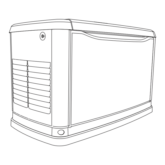
Section 2: General Information Section 2: General Information The Generator 000908 000909 Figure 2-1. GH-410 Engine 8 kW Unit (Left) and GH-530 Engine 11 kW Unit (Right) 000910 Figure 2-2. GT-990/GT-999 Engines, 16-22 kW Units Exhaust Enclosure Battery Compartment Circuit Breakers... -
Page 10: Generator
Section 2: General Information Specifications Generator Model 8 kW 11 kW 16 kW 17 kW 20 kW 22 kW Rated Voltage Rated Maximum Load Current (Amps) at Rated 33.3 45.8 66.6 70.8 83.3 91.7 Voltage* Main Circuit Breaker 35 Amp... -
Page 11: Protection Systems
Section 2: General Information Protection Systems System Components The generator may have to run for long periods of time with no operator present to monitor the engine/generator - Intake Manifold Air Induction conditions. Therefore, the generator is equipped with a - Air Cleaner number of systems to automatically shut down the unit to - Carburetor and Mixer Assembly... -
Page 12: Replacement Parts
Section 2: General Information Replacement Parts Description 8 kW 11 kW 16/17 kW 20 kW 22 kW 26R Exide Battery 0H3421S Spark Plug 0G0767B 0E9368 0E7585A 0G0767A 0G0767A Oil Filter 070185E Air Filter 0E9371A 0J8478 Control Panel Fuse 0D7178T Transfer Switch Fuses... -
Page 13: Section 3: Operation
Section 3: Operation Section 3: Operation Site Prep Verification Main Circuit Breaker (Generator Disconnect) This is a 2-pole breaker rated according to relevant spec- It is important that the generator is installed in such a way ifications. See “A” in Figure 3-1 that the airflow into and out of the generator is not impeded. - Page 14 Section 3: Operation There are two locks securing the lid, one on each side (A in Figure 3-3). To properly open the lid, press down, on the lid, above the side lock and unlock the latch. Repeat for the other side. If pressure is not applied from the top, the lid may appear stuck.
-
Page 15: Control Panel Interface
Section 3: Operation Control Panel Interface The Control Panel Interface is located under the lid of the enclosure. Before attempting to lift the lid of the enclosure, verify that both left and right side locks are unlocked. To remove the front cover, lift the cover straight up to disengage the side hooks, then tilt and lift it away from the unit. - Page 16 Section 3: Operation EVOLUTION/SYNC2.0 HSB MENU MAP Switched to “OFF” Note: Menu functions and features may vary Hours of Protection 0 (H) depending on unit model and firmware revision. Running Manual Running-Utility Lost Running-Remote Start ENTER SYSTEM DATE/TIME Running-2 Wire Start Running - Exercise Switched Off ENTER...
- Page 17 Section 3: Operation Current Date/Time UP ARROW = 02/14/13 07:40 DOWN ARROW = ENTER Run Hours (H) ENTER MAINT: Run Hrs MAIN ENTER Maint. Log Scheduled DEALER Access Requires Password ENTER ENTER - 1 thru 50 + EXAMPLE: "Battery Maintained" Inspect Battery 200 RnHr or 12/27/13 "Schedule A Serviced"...
-
Page 18: Setting The Exercise Timer
16-20 kW generators. Exercise Time 000906 8-11 kW generators exercise at a constant 3600 rpm. Figure 3-8. Table 3-1. Generator Exercise Characteristics Generator Size 8 kW 11 kW 16 kW / 20 kW 22 kW Low Speed Exercise n/a * n/a *... -
Page 19: Transfer To Generator Power Source
Section 3: Operation Prior to automatic operation, manually exercise the Set the main circuit breaker (Generator Disconnect) transfer switch to verify that there is no interference with to ON or CLOSED. The standby power source now proper operation of the mechanism. Manual operation of powers the loads. -
Page 20: Automatic Transfer Operation
The system will control the cyclic cranking as follows: • 8 kW Unit: 5 cranking cycles as follows: 15 second To turn the generator OFF (while running in crank, seven (7) second rest, followed by four (4) -
Page 21: Section 4: Maintenance
Section 4: Maintenance Section 4: Maintenance NOTE: Proper maintenance and proper and safe Service and repairs may be performed by any qualified operation is crucial to the life of the generator. Genuine service person or repair shop. Generac parts MUST be used to ensure warranty Engine oil and filter must be changed and valve lash coverage. -
Page 22: Checking Engine Oil Level
Section 4: Maintenance Maintenance Log Battery inspection and charge check Dates Performed: Oil, oil filter, air filter and spark plug replacement Dates Performed: Valve Adjustment Dates Performed: Checking Engine Oil Level residence using electrical panel main disconnect. Then, turn the generator main circuit WARNING breaker to the OFF position. -
Page 23: Changing The Oil And Oil Filter
A few minutes after the engine shuts OFF, when it kW), or close the air cleaner access door and has cooled slightly, lift the lid and remove the front engage the wire clip (8 kW). panel. Pull the oil drain hose free of its retaining clip. See A in... -
Page 24: Valve Lash Adjustment
Section 4: Maintenance Clean the plug(s) by scraping or washing with a • Remove spark plugs. wire brush and commercial solvent. Do not blast • Make sure the piston is at top dead center (TDC) of the plug(s) to clean. its compression stroke (both valves closed). -
Page 25: Attention After Submersion
Section 4: Maintenance Inspect the battery posts and cables for tightness • Wash down spilled electrolyte with an aid and corrosion. Tighten and clean as necessary. neutralizing agent. A common practice is to use a solution of 500 grams (1 pound) bicarbonate of Check the battery fluid level of unsealed batteries, soda to 4 liters (1 gallon) of water. -
Page 26: Return To Service
Section 4: Maintenance Turn off the utility power to the transfer switch. Remove the 7.5 Amp fuse from the generator’s control panel. Disconnect the battery cables. Remove negative cable first. Remove battery charger AC input T1/Neutral cable (has white sleeve) at controller. While the engine is still warm, drain the oil completely, and then refill the crankcase with oil. -
Page 27: Section 5: Troubleshooting
Section 5: Troubleshooting Section 5: Troubleshooting System Diagnosis Problem Cause Correction Engine will not crank. 1. Fuse blown. 1. Correct short circuit condition by replacing 7.5 Amp fuse in generator control panel. 2. Loose, corroded or defective battery 2. Tighten, clean or replace as necessary.* cables. - Page 28 Section 5: Troubleshooting This page intentionally left blank. Owner’s Manual for 60 Hz Air-cooled Generators...
-
Page 29: Section 6: Quick Reference Guide
Section 6: Quick Reference Guide Section 6: Quick Reference Guide System Diagnosis To clear an active alarm, press the ENTER button twice and then press AUTO. If the alarm reoccurs, contact an Inde- pendent Authorized Service Dealer. Table 6-1. System Diagnosis Active Alarm Problem Things to Check... - Page 30 Section 6: Quick Reference Guide Table 6-1. System Diagnosis (Continued) Active Alarm Problem Things to Check Solution Unit will not start in Check the LED’s / Contact Independent Authorized Service OVERSPEED AUTO with utility loss. Screen for alarms. Dealer. Unit will not start in Check the LED’s / Contact Independent Authorized Service UNDERVOLTAGE...
- Page 32 Generac Power Systems S45 W29290 Hwy 59 Waukesha, WI 53187 The Honeywell trademark is used under license from Honeywell International Inc. 1-855-GEN-INFO Honeywell International Inc. makes no representation or warranties with respect honeywellgenerators.com to this product. Part No. 0K5801Y12SPFR Revision E (09/28/15)
- Page 33 Manual del propietario Generadores enfriados por aire de 60 Hz 8 kW a 22 kW Register your Honeywell product at: WWW.HONEYWELLGENERATORS.COM 855-436-4636 Para español, visite: http://www.generac.com/service-support/product-support-lookup Pour le français, visiter : http://www.generac.com/service-support/product-support-lookup GUARDE ESTE MANUAL PARA REFERENCIA EN EL FUTURO...
-
Page 34: Información General
Use esta página para registrar información importante acerca de su equipo generador. Registre en esta página la información que se encuentra en la etiqueta de datos de su unidad. Para la ubicación de la Modelo: etiqueta de datos de la unidad, vea Información general. - Page 35 Índice Índice Transferencia a la fuente de Section 1: Reglas de seguridad e alimentación del generador ........15 información general Transferencia de vuelta a la fuente de alimentación Introducción ............1 del servicio público ............15 Lea este manual minuciosamente .......1 Operación de transferencia automática ..16 Cómo obtener servicio ..........1 Secuencia de funcionamiento automático ..
- Page 36 Índice Esta página se ha dejado en blanco intencionalmente. Manual del propietario para generadores enfriados por aire de 60 Hz...
-
Page 37: Introducción
Sección 1: Reglas de seguridad e información general Sección 1: Reglas de seguridad e información general Introducción Gracias por comprar este generador accionado por motor, enfriado por aire, compacto y de alto rendimiento. Está diseñado para suministrar alimentación eléctrica automáticamente para hacer funcionar cargas eléctricas críticas durante un fallo de alimentación del servicio público. -
Page 38: Peligros Generales
Sección 1: Reglas de seguridad e información general Peligros generales Cuando trabaje en este equipo, manténgase alerta en • todo momento. Nunca trabaje en el equipo cuando esté fatigado física o mentalmente. Inspeccione el generador regularmente, y comuníquese • concesionario servicio autorizado independiente más cercano en relación con las piezas... -
Page 39: Peligros Eléctricos
Sección 1: Reglas de seguridad e información general Peligros eléctricos Peligros de incendio • Para seguridad contra incendios, el generador se debe instalar y mantener apropiadamente. La instalación siempre debe cumplir los códigos, normas, leyes y reglamentos correspondientes. Observe estrictamente los códigos eléctrico y de construcción locales, estatales y nacionales. - Page 40 Sección 1: Reglas de seguridad e información general Esta página se ha dejado en blanco intencionalmente. Manual del propietario para generadores enfriados por aire de 60 Hz...
-
Page 41: El Generador
Sección 2: Información general Sección 2: Información general El generador Figura 2-1. Unidad GH-410 con motor de 8 kW (izquierda) y unidad GH-530 con motor de 11 kW (derecha) Figura 2-2. Unidades GT-990/GT-999 con motores de 16-22 kW Cerramiento del escape Compartimiento de baterías... -
Page 42: Generador
Sección 2: Información general Especificaciones Generador Modelo 8 kW 11 kW 16 kW 17 kW 20 kW 22 kW Voltaje nominal Corriente de carga nominal máxima (A) con el voltaje 33.3 45.8 66.6 70.8 83.3 91.7 nominal* Disyuntor principal 35 A... -
Page 43: Sistemas De Protección
Sección 2: Información general Sistemas de protección Sistema Componentes El generador puede tener que funcionar durante períodos prolongados sin operador presente para monitorizar las - Colector de admisión Inducción de aire condiciones del motor y generador. Por lo tanto, el generador - Depurador de aire tiene una cantidad de sistemas para parar automáticamente la Dosificador de... - Page 44 Sección 2: Información general Piezas de repuesto Partes Descripción 8 kW 11 kW 16/17 kW 20 kW 22 kW Batería Exide 26R 0H3421S Bujía 0G0767B 0E9368 0E7585A 0G0767A 0G0767A Filtro de aceite 070185E Filtro de aire 0E9371A 0J8478 Fusible del tablero de...
-
Page 45: Verificación De La Preparación Del Sitio
Sección 3: Operación Sección 3: Operación Verificación de la preparación del Disyuntor principal (Interruptor de desconexión del generador) sitio Este es un disyuntor de 2 polos con valor nominal de acuerdo Es importante que el generador se instale de manera tal que no se con las especificaciones relevantes. - Page 46 Sección 3: Operación Hay dos cerraduras que fijan la tapa, una a cada lado (A ). Para abrir la tapa correctamente, Figura 3-3 presione hacia abajo en la tapa sobre el cierre lateral y desenganche el pestillo. Repita en el otro lado. Si no se aplica presión sobre la parte superior, la tapa puede aparecer atorada.
-
Page 47: Interfaz Del Tablero De Control
Sección 3: Operación Interfaz del tablero de control La interfaz del tablero de control está ubicada debajo de la tapa del gabinete. Antes de intentar levantar la tapa del gabinete, verifique que ambas cerraduras laterales izquierda y derecha estén abiertas. Para retirar la cubierta delantera, levante la cubierta recta hacia arriba para desenganchar los ganchos laterales, luego inclínela y levántela alejándola de la unidad. - Page 48 Sección 3: Operación DIAGRAMA DEL MENÚ DE HSB EVOLUTION/SYNC2.0 Conmutado a “OFF” Horas de protección Nota: Las funciones y características del menú 0 (h) pueden variar según el modelo de la unidad y la revisión del firmware. Funcionamiento manual Funcionando-Pérdida servicio público Funcionando-Arranque remoto SISTEMA...
- Page 49 Sección 3: Operación FLECHA Fecha/hora actual ARRIBA = + 02/14/13 07:40 FLECHA ABAJO = - ENTER Horas de funcionamiento (h) ENTER Horas de MANTENIMIENTO: funcionamiento MANTENIMIENTO Reg. de ENTER Programadas mantenimiento ONCESIONARIO El acceso requiere contraseña ENTER ENTER EJEMPLO: - 1 a 50 + Inspeccionar batería a las 200 horas de “Batería mantenida”...
-
Page 50: Configuración Del Temporizador De Ejercitación
16-20 kW. Los Figura 3-8. generadores de 8-11 kW se ejercitan con 3600 rpm constantes. Tabla 3-1. Características de la ejercitación del generador Tamaño del generador 8 kW 11 kW 16 kW/20 kW 22 kW n/d *... -
Page 51: Transferencia A La Fuente De Alimentación Del Generador
Sección 3: Operación Antes del funcionamiento automático, ejercite manualmente el Ajuste el disyuntor principal (desconexión del generador) interruptor de transferencia para verificar que no haya en ON o CERRADO. La fuente de alimentación de interferencias con la operación correcta del mecanismo. La respaldo ahora alimenta a las cargas. -
Page 52: Operación De Transferencia Automática
Para apagar el generador (mientras funciona en El sistema controlará los giros de arranque cíclicos como sigue: AUTO y en línea): Unidad de 8 kW: 5 ciclos de giros de arranque como • Ajuste en OFF el interruptor de desconexión principal del sigue: 15 segundos de giros de arranque, (7) segundos de servicio público. -
Page 53: Section 4: Mantenimiento
Sección 4: Mantenimiento Sección 4: Mantenimiento Después de las primeras 25 horas de funcionamiento se debe: El mantenimiento correcto y la operación correcta y NOTA: cambiar el aceite de motor, sustituir el filtro de aceite y ajustar segura son cruciales para la duración del generador. DEBEN la luz de válvulas. -
Page 54: Comprobación Del Nivel De Aceite De Motor
Sección 4: Mantenimiento Registro de mantenimiento Inspección de la batería y comprobación de la carga Fechas en que se efectuó: Cambio de aceite, filtro de aceite, filtro de aire y bujía Fechas en que se efectuó: Ajuste de válvulas Fechas en que se efectuó: todas las cargas asociadas que funcionan en la Comprobación del nivel de residencia usando la desconexión principal del tablero... -
Page 55: Cambio De Aceite Y Filtro De Aceite
Ponga en marcha el motor pulsando el botón MANUAL aire (8 kW). en el tablero de control y permita que el motor funcione Extraiga el filtro de aire antiguo y deséchelo. -
Page 56: Ajuste De La Luz De Válvulas
Sección 4: Mantenimiento Limpie la(s) bujía(s) raspando o lavando con un cepillo Retire las bujías. • de alambre y solvente comercial. No arene la(s) bujía(s) Asegúrese de que el pistón esté en el punto muerto superior • para limpiarla(s). (PMS) de su carrera de compresión (ambas válvulas Compruebe la separación de los electrodos de bujía cerradas). -
Page 57: Atención Después De Una Inmersión
Sección 4: Mantenimiento Compruebe el nivel de fluido de la batería en las reacción (espumación). El líquido resultante se debe baterías no selladas y, de ser necesario, llene solo con lavar con agua y la zona se debe secar. agua destilada. NO use agua corriente. También haga NO fume cerca de la batería. -
Page 58: Reintegro Al Servicio
Sección 4: Mantenimiento Retire el cable de entrada de CA al cargador de baterías T1/neutro (tiene una camisa blanca) en el controlador. Mientras motor aún está caliente, vacíe completamente el aceite y luego llene el cárter con aceite. Fije un rótulo en el motor que indique la viscosidad y clasificación del aceite nuevo en el cárter. - Page 59 Sección 5: Resolución de problemas Sección 5: Resolución de problemas Diagnóstico del sistema Problema Causa Corrección El motor no efectúa giros de 1. Fusible quemado. 1. Corrija la condición de cortocircuito sustituyendo el arranque. fusible de 7.5 A en el tablero de control del generador.
- Page 60 Sección 5: Resolución de problemas Esta página se ha dejado en blanco intencionalmente. Manual del propietario para generadores enfriados por aire de 60 Hz...
- Page 61 Sección 6: Guía de referencia rápida Sección 6: Guía de referencia rápida Diagnóstico del sistema Para desactivar una alarma activa, pulse el botón ENTER dos veces y luego pulse AUTO. Si la alarma vuelve a aparecer, comuníquese con un concesionario de servicio autorizado independiente. Tabla 6-1.
- Page 62 Sección 6: Guía de referencia rápida Tabla 6-1. Diagnóstico del sistema (Continuación) Cosas a Alarma activa Problema Solución comprobar La unidad no se pone en Compruebe los LED y la Desactive la alarma y retire las cargas domésticas VOLTAJE BAJO, ROJO marcha en AUTO (Automático) pantalla en busca de...
- Page 64 Generac Power Systems S45 W29290 Hwy 59 Waukesha, WI 53187, EE. UU. La marca comercial Honeywell se usa bajo licencia de Honeywell International Inc. 1-855-GEN-INFO Honeywell International Inc. no efectúa ninguna declaración ni otorga garantías con honeywellgenerators.com respecto a este producto.
- Page 65 Manuel de l’utilisateur Générateurs refroidis à l’air de 60 Hz de 8 kW à 22 kW Register your Honeywell product at: WWW.HONEYWELLGENERATORS.COM 855-436-4636 Para español, visita : http://www.generac.com/service-support/product-support-lookup Pour le français, visiter: http://www.generac.com/service-support/product-support-lookup CONSERVEZ CE MANUEL À TITRE DE RÉFÉRENCE ULTÉRIEURE.
- Page 66 Utilisez cette page pour noter des informations importantes concernant votre générateur. Prenez note des informations relevées sur la plaque signalétique de votre appareil sur cette page. Pour connaître Modèle : l’emplacement de la plaque signalétique de votre appareil, consultez Informations générales.
- Page 67 Table des matières Table des matières Section 1: Règles de sécurité et informations Fonctionnement automatique du commutateur de transfert ......18 générales Séquence de fonctionnement automatique ..18 Introduction ............1 Panne du réseau public ..........18 Lire ce manuel attentivement ........1 Lancement du moteur ..........18 Comment obtenir des services d’entretien et de réparation ..............1...
- Page 68 Table des matières Manuel du propriétaire pour les générateurs refroidis à l’air de 60 Hz...
-
Page 69: Section 1: Règles De Sécurité Et Informations Générales
Section 1 : Règles de sécurité et informations générales Section 1 : Règles de sécurité et informations générales Introduction Nous vous remercions d’avoir acheté ce générateur compact, haute performance, à refroidissement à air et entraîné par moteur. Ce générateur a été conçu de manière à... -
Page 70: Règles De Sécurité
Section 1 : Règles de sécurité et informations générales Lorsque vous communiquez avec un fournisseur au sujet de pièces et de services d’entretien et de réparation, assurez-vous d’avoir le numéro complet du modèle et le numéro de série de l’appareil, tels qu’ils sont fournis sur l’autocollant placé... -
Page 71: Risques Relatifs Aux Gaz D'échappement
Section 1 : Règles de sécurité et informations générales Risques de décharge électrique AVERTISSEMENT Dommages à l’équipement et aux biens. Ne modifiez pas la construction ni l’installation du générateur et ne bloquez pas la ventilation. Le non-respect de cette consigne pourrait endommager le générateur ou le rendre dangereux. -
Page 72: Risques D'incendie
Section 1 : Règles de sécurité et informations générales Risques d’incendie DANGER AVERTISSEMENT Risque d’incendie. Laissez les déversements d’essence sécher complètement avant de Risque d’incendie. L’appareil doit être positionné démarrer le moteur. Le non-respect de cette de manière à prévenir l’accumulation de matière consigne entraînera la mort ou des combustible en dessous. -
Page 73: Section 2: Informations Générales Le Générateur
Section 2 : Informations générales Section 2 : Informations générales Le générateur Figure 2-1. Moteur GH-410, appareil de 8 kW (gauche) et moteur GH-530, appareil de 11 kW (droite) Figure 2-2. Moteurs GT-990/GT-999, appareils de 16-22 kW Boîtier d’échappe- Logement à batterie Disjoncteurs Bouchon de l’ori-... -
Page 74: Générateur
Section 2 : Informations générales Caractéristiques techniques Générateur Modèle 8 kW 11 kW 16 kW 17 kW 20 kW 22 kW Tension nominale Courant de charge maximal 33.3 45.8 66.6 70.8 83.3 91.7 (A) à une tension nominale* Disjoncteur principal... -
Page 75: Systèmes De Protection
Section 2 : Informations générales Systèmes de protection Le code du système antipollution est EM (Modification du moteur). Le système antipollution installé sur le générateur Le générateur peut devoir fonctionner pendant de longues est constitué des composants suivants : périodes sans la présence d’un utilisateur pour surveiller l’état du moteur et du générateur. - Page 76 Section 2 : Informations générales Pièces de rechange Description 8 kW 11 kW 16/17 kW 20 kW 22 kW Batterie Exide 26R 0H3421S Bougie d’allumage 0G0767B 0E9368 0E7585A 0G0767A 0G0767A Filtre à huile 070185E Filtre à air 0E9371A 0J8478 Fusible du tableau de...
-
Page 77: Section 3: Fonctionnement
Section 3 : Fonctionnement Section 3 : Fonctionnement Vérification de la préparation Disjoncteur du circuit principal (déconnexion du générateur) du site Il s’agit d’un disjoncteur à 2 pôles dont les valeurs Il est important que le générateur soit installé de manière nominales correspondent aux caractéristiques techniques à... - Page 78 Section 3 : Fonctionnement Deux verrous ferment le couvercle, un de chaque côté (A dans Figure 3-3). Pour ouvrir le couvercle correctement, appuyez sur le couvercle à l’endroit des verrous latéraux et déverrouillez-les un côté à la fois. Si la pression ne provient pas du haut, le couvercle peut sembler bloqué.
-
Page 79: Interface Du Tableau De Commande
Section 3 : Fonctionnement Interface du tableau de commande L’interface du panneau de commande est située sous le couvercle de l’enceinte. Avant d’essayer de soulever le couvercle de l’enceinte, vérifiez que les verrous latéraux gauche et droit sont déverrouillés. Pour retirer le couvercle avant, soulevez le couvercle vers le haut pour dégager les crochets latéraux, puis inclinez-le et soulevez-le de l’appareil. - Page 80 Section 3 : Fonctionnement SCHÉMA DU MENU DU EVOLUTION/SYNC2.0 HSB Mis sur « ARRÊT » Heures de protection Remarque : Les fonctions et fonctionnalités du menu 0 (H) peuvent changer suivant le modèle de l'appareil et de la version du micrologiciel. ÉCHAP Fonctionnement manuel Fonctionnement-Panne du réseau...
- Page 81 Section 3 : Fonctionnement FLÈCHE HAUT = + Date/Heure actuelles 02/14/13 07:40 ÉCHAP FLÈCHE BAS = - ENTRÉE Heures fonct. (h) ÉCHAP ENTRÉE ENTRET. : Heures fonct. ÉCHAP ENTRET. ENTRÉE Maint. Journ. Programm. FOURN. SERV. Accès exigeant mot de passe ENTRET.
-
Page 82: Réglage De La Minuterie D'exercice
16-20 kW. Les générateurs de 8-11 kW Figure 3-8. Table 3-1. Caractéristiques de l’exercice du générateur Puissance du 8 kW 11 kW 16 kW / 20 kW 22 kW générateur Exercice à... -
Page 83: Transfert À La Source D'alimentation Du Générateur
Section 3 : Fonctionnement Transfert à la source d’alimentation du générateur Assurez-vous que le générateur est à la position OFF (arrêt). Réglez disjoncteur circuit principal (déconnexion du générateur) sur la position OFF (arrêt) ou OPEN (ouvert). Coupez l’alimentation réseau public commutateur de transfert à... -
Page 84: Fonctionnement Automatique Du Commutateur De Transfert
: Mettez le disjoncteur principal du générateur (DLP) à • Unité de 8 kW : Voici les cinq cycles de démarrage : la position OFF (arrêt) (ou OPEN [ouvert]). Lancement de 15 secondes, sept (7) secondes de Mettez le générateur en position OFF (arrêt). -
Page 85: Section 4: Maintenance
Section 4 : Maintenance Section 4 : Maintenance REMARQUE : Un bon entretien et un fonctionnement L’huile du moteur et le filtre doivent être changés et le jeu des soupapes réglé après les 25 premières heures de correct et sûr sont essentiels à la durée de vie du générateur. fonctionnement. -
Page 86: Vérification Du Niveau D'huile Du Moteur
Section 4 : Maintenance Journal d’entretien Inspection de la batterie et vérification de la charge Dates d’exécution : Remplacement de l’huile, du filtre à air et des bougies d’allumage Dates d’exécution : Réglage des soupapes Dates d’exécution : Vérification du niveau d’huile du par mettre HORS TENSION tous les appareils de la résidence par l’interrupteur principal du panneau moteur... -
Page 87: Remplacement De L'huile Et Du Filtre À Huile
Dégagez le tuyau de vidange d’huile métallique et ouvrez la porte d’accès au filtre à air en le libérant de sa pince de fixation. Voir A dans (8 kW). Figure 4-2 Retirez le bouchon du tuyau et vidangez l’huile dans un récipient approprié. -
Page 88: Bougies D'allumage
Section 4 : Maintenance Installez le couvercle du filtre à air et les pinces du couvercle (11-22 kW), ou fermez la porte d’accès au filtre à air et enclenchez la broche métallique (8 kW). Bougies d’allumage Réglez l’écartement des bougies d’allumage ou remplacez- les le cas échéant :... -
Page 89: Entretien De La Batterie
Section 4 : Maintenance d’une jauge d’épaisseur. Le jeu correct est conforme AVERTISSEMENT aux spécifications énoncées à la section 2 Moteur. REMARQUE : Maintenez le contre-écrou du culbuteur en Décharge électrique. Débranchez la borne de place lorsque vous tournez le pivot à rotule. mise à... -
Page 90: Protection Contre La Corrosion
Section 4 : Maintenance sécher et de l’inspecter soigneusement. Si la structure Apposez une étiquette sur le moteur indiquant la (résidence) a été inondée, elle doit être inspectée par un viscosité et la classification de la nouvelle huile dans le électricien qualifié... -
Page 91: Section 5: Dépannage
Section 5 : Dépannage Section 8 : Dépannage Diagnostic du système Problème Cause Correction Le moteur ne tourne pas. 1. Fusible sauté. 1. Corrigez l’état de court-circuit en remplaçant le fusible de 7,5 A dans le tableau de commande du générateur. - Page 92 Section 5 : Dépannage Page laissée en blanc intentionnellement. Manuel du propriétaire pour les générateurs refroidis à l’air de 60 Hz...
-
Page 93: Section 6: Guide De Référence Rapide
Section 6 : Guide de référence rapide Section 9 : Guide de référence rapide Diagnostic du système Pour supprimer une alarme active, appuyez sur la touche ENTER (entrer) deux fois, puis sur AUTO. Si l’alarme se fait entendre de nouveau, communiquez avec un fournisseur de services d’entretien agréé indépendant. Table 9-1. - Page 94 Section 6 : Guide de référence rapide Table 9-1. Diagnostic du système (suite) Voyant Éléments à Alarme active Problème Solution vérifier TENSION FAIBLE – L’appareil ne démarre pas Vérifiez s’il y a des Supprimez l’alarme et retirez les charges RETRAIT DE ROUGE en mode AUTO sans alarmes sur l’écran ou...
- Page 96 Generac Power Systems, Inc. S45 W29290 Hwy 59 Waukesha, WI 53187 La marque de commerce Honeywell est utilisée avec l’autorisation de Honeywell 1-855-GEN-INFO International Inc. Honeywell International Inc. ne formule aucune déclaration et honeywellgenerators.com n’offre aucune garantie concernant ce produit.