Makita LS1040 Instruction Manual
Hide thumbs
Also See for LS1040:
- User manual ,
- Instruction manual (113 pages) ,
- Parts breakdown (5 pages)

Related Manuals for Makita LS1040


Summary of Contents for Makita LS1040
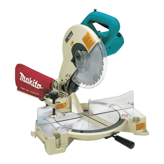
- Page 1 Compound Miter Saw MODEL LS1040 MODEL LS1040S 001854 DOUBLE INSULATION I N S T R U C T I O N M A N U A L WARNING: For your personal safety, READ and UNDERSTAND before using. SAVE THESE INSTRUCTIONS FOR FUTURE REFERENCE.
-
Page 2: Specifications
SPECIFICATIONS Model ..............................LS1040/LS1040S Blade diameter............................. 255 mm -260 mm Hole diameter For all countries other than European countries ................25.4 mm and 25 mm For European countries ............................30 mm Max. Cutting capacities (H x W) with blade 260 mm in diameter... -
Page 3: Safety Instructions
For Model LS1040 The typical weighted root mean square acceleration For public low-voltage distribution systems of value is not more than 2.5 m/s between 220 V and 250 V. EC-DECLARATION OF CONFORMITY Switching operations of electric apparatus cause voltage We declare under our sole responsibility that this product fluctuations. -
Page 4: Additional Safety Rules For Tool
periodically and if damaged have it repaired by an that is damaged should be carefully checked to authorized service facility. Inspect extension cords determine that it will operate properly and perform periodically and replace, if damaged. Keep handles its intended function. Check for alignment of moving dry, clean and free from oil and grease. - Page 5 24. Always use accessories recommended in this man- • arsenic and chromium from chemically- ual. Use of improper accessories such as abrasive treated lumber. wheels may cause an injury. Your risk from these exposures varies, depend- 25. Do not use the saw to cut other than aluminum, ing on how often you do this type of work.
-
Page 6: Installation
INSTALLATION Installing auxiliary plate 001855 Install the auxiliary plate using the notch in the tool’s base and secure it by tightening the hex bolt. 1. Auxiliary plate 2. Hex bolt 3. Base 001832 1. Auxiliary plate 2. Base 3. Hex bolt 4. -
Page 7: Blade Guard
FUNCTIONAL CAUTION: DESCRIPTION • Always be sure that the tool is switched off and unplugged before adjusting or checking function on the tool. Blade guard 001860 When lowering the handle, the blade guard rises automatically. The guard is spring loaded so it returns to its original position when the cut is completed and the handle is raised. - Page 8 Maintaining maximum cutting capacity 002257 This tool is factory adjusted to provide the maximum cutting capacity for a 260 mm saw blade. When installing a new blade, always check the lower limit position of the blade and if necessary, adjust it as follows: First, unplug the tool.
-
Page 9: Adjusting Bevel Angle
Adjusting the bevel angle 001864 To adjust the bevel angle, loosen the lever at the rear of the tool counterclock- wise. Push the handle to the left to tilt the saw blade until the pointer points to the desired angle on the bevel scale. Then tighten the lever clockwise firmly to secure the arm. - Page 10 NEVER use the tool if it runs when you 2. Switch trigger simply pull the switch trigger without pressing the lock-off button. Return tool to a Makita service center for proper repairs BEFORE further usage. • NEVER tape down or defeat purpose and function of lock-off button.
-
Page 11: Securing Workpiece
Empty the dust bag of its contents, tapping it lightly so as to remove particles adhering to the insides which might hamper further collec- tion. NOTE: If you connect a Makita vacuum cleaner to your saw, more efficient and 1. Dust nozzle cleaner operations can be performed. 2. Dust bag 3. - Page 12 001549 CAUTION: • When cutting long workpieces, use supports that are as high as the top surface level of the turn base. Do not rely solely on the vertical vise and/ or horizontal vise to secure the workpiece. Thin material tends to sag. Support workpiece over its entire length to avoid blade pinch and possible KICKBACK.
- Page 13 Horizontal vise (optional accessory) 001807 The horizontal vise can be installed on either the left or right side of the base. When performing 15° or greater miter cuts, install the horizontal vise on the side opposite the direction in which the turn base is to be turned. By turning the vise knob counterclockwise, the screw is released and the vise shaft can be moved rapidly in and out.
-
Page 14: Operation
OPERATION CAUTION: • Before use, be sure to release the handle from the lowered position by pulling the stopper pin. • Make sure the blade is not contacting the workpiece, etc. before the switch is turned on. • Do not apply excessive pressure on the handle when cutting. Too much force may result in overload of the motor and/or decreased cutting efficiency. - Page 15 When performing compound cutting, refer to “Press cutting”, “Miter cut- ting” and “Bevel cut” explanations. Cutting aluminum extrusion 001844 When securing aluminum extrusions, use spacer blocks or pieces of scrap as shown in the figure to prevent deformation of the aluminum. Use a cutting lubricant when cutting the aluminum extrusion to prevent build- up of the aluminum material on the blade.
-
Page 16: Maintenance
Carrying tool 001792 Make sure that the tool is unplugged. Secure the blade at 0° bevel angle and the turn base at right miter angle fully. Lower the handle fully and lock it in the lowered position by pushing in the stopper pin. 1. - Page 17 Lower the handle fully and lock it in the lowered position by pushing in 002259 the stopper pin. Square the side of the blade with the face of the guide fence using a triangular rule, try-square, etc. Then securely tighten the hex bolts on the guide fence in the order from the right side.
-
Page 18: After Use
“Blade guard”. Lubricate the sliding portions with machine oil to prevent rust. To maintain product SAFETY and RELIABILITY, repairs, any other mainte- nance or adjustment should be performed by Makita Authorized Service Cent- ers, always using Makita replacement parts. - Page 19 CAUTION: • These accessories or attachments are recommended for use with your Makita tool specified in this manual. The use of any other accessories or attachments might present a risk of injury to persons. Only use accessory or attachment for its stated purpose.
- Page 20 Makita Corporation Anjo, Aichi, Japan 884085C228...