Table of Contents
Advertisement
Quick Links
Advertisement
Table of Contents

Related Manuals for Parweld DP231C


Summary of Contents for Parweld DP231C
- Page 1 User Manual DP231C ISSUE 2...
-
Page 5: Data Plate
DATA PLATE 1. MANUFACTURER’S NAME, ADRESS AND COMPANY LOGO 2. MODEL 3. SERIAL NUMBER 4. BLOCK DIAGRAM 5. WELDING OUTPUT 6. SUITABLE FOR ENVIRONMENT WITH INCREASED HAZARD OF ELECTRIC SHOCK 7. POWER SUPPLY 8. DEGREE OF PROTECTION 9. TYPE OF WELDING OUTPUT CURRENT 10. -
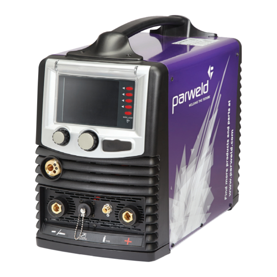
Page 6: Description Of The Equipment
GENERAL SPECIFICATIONS AND NOTES providing an optimal antitheft system and FOR CONSULTING THIS MANUAL safeguard against inappropriate use. Thanks “DP231C” welders made using to the advanced control techniques adopted, INVERTER technology. They are extremely the product is extremely reliable and easy to compact and versatile devices that can be used use. - Page 7 10. Mode: GAS connection to the cylinder MIG Mode with gas: GAS connection to the cylinder VIEWS: - At start-up, the Parweld logo and the 20. Fuse Firmware revision are displayed. 21.Connector for supplying power to the CONTROL BUTTONS: (2, 3, 4, 5,6 in fig.1)
-
Page 8: Wire-Feeder Motor
Fig.3A Fig.3 FIGURE 3: 22. WIRE SPOOL SUPPORT The 300mm MIG welding spool requires an external 28. GAS VALVE: The Gas Valve can be rotated support in three positions. 23. WIRE FEEDER SYSTEM: see figure 3A for Position: feeds a more detailed image. Euroconnector with the gas from the cylinder 24. -
Page 9: Welding Wire
WELDING WIRE 6. Lower the roll To load the welding wire, follow these instructions feeder (25 of Fig. carefully, in the order described below. Warning: before inserting the wire, always remove the gas nozzle and the wire feeder tip from the welding torch. - Page 10 a ‘V’ cable are suitable for feeding iron and Switch 9 adjusts the machine power. steel wire. The spools with a ‘U’ are suitable for There are three principal MIG-MAG welding aluminium wire. modes: 1.Manual short arc 4. MIG/MAG WELDING To choose this welding 2.Synergic short arc mode use switch 10, select MIG and press 3.Pulsed arc synergic...
- Page 11 soft-start: This adjusts the contact speed of the setting. Welding quality can be further improved wire, creating a softer weld spark; the higher the by adjusting the ‘electronic inductance’ and level the lower the contact speed. ‘deposit’ settings. Inductance: This adjusts the variation speed of Turn switch 10 to choose from the different MIG- the welding current for a sharper (low levels) or MAG welding options;...
- Page 12 Once the type of wire has been selected (using L2 span: When the two level mode is active the switch 10), the settings page for the welding wire duration of the second power level can be set. diameter will appear. L2 amplitude: When the two level mode is active the second power level (L2) can be set with respect to the set power (level L1).
- Page 13 the tip of the torch, when the welding process comes to an end. Soft-start: this adjusts the Once the type of wire has been selected(using contact speed of the wire, to obtain a soft weld switch 10), the settings page for the welding wire spark;...
-
Page 14: Mig Welding Conector
L1 span: When the two level mode is active the the welding current supply ends. 13 duration of the first power level can be set. Burnback: This adjusts the length of the wire in L2 span: When the two level mode is active the the tip of the torch, when the welding process duration of the second power level can be set. -
Page 15: Adjusting The Welder
for the MIG welding torch (Fig 4) This accessory SHORT ARC (short-circuit transfer):this brings has a long life-time if periodical controls of the the electrode into direct contact with the gas nozzle and the wire feeder tip are carried out weld pool, which creates a short-circuit that (Fig 4A) (Fig 4B).These parts must be kept well- extinguishes the arc, after which the arc reignites... -
Page 16: Welding Process
With the DP231C it is possible to weld any type of electrode and diameter. The spark of the arc occurs by placing the electrode close to the workpiece. -
Page 17: Connection For Mma Welding
Arc Force: This sets the current increase ratio in welding. 4Bi: relation to the welding current, that the welder can force, in order to keep the arc appropriately Create the contact ignited in any position. for igniting the arc Hot Start: This sets the current increase ratio in distance relation to the welding current, that the welder approximately... -
Page 18: Adjustments And Settings
13. TIG WELDING To select this welding mode : 13.1 TIG WELDING (Lift-Arc) Button 9 controls turn switch 10, select TIG and press confirm. the current and the machine power. Select this option and the welding screen will Inert gas (Argon) welding with an infusible appear: Tungsten electrode and arc (often call TIG (Tungsten Inert Gas) for short, is a welding... -
Page 19: Connector For Tig Welding
initial current settings. TIG WELDING: Before connecting the gas make slope up: This sets the upslope of the welding sure the cylinder contains pure Argon gas. Never current. use any other type of gas. Connect the pressure slope down: This sets the duration of the down- regulator to the cylinder, after which, connect the slope time of the welding current. -
Page 20: Power Connector
Where: Sw is the torch trigger P is the potentiometer for controlling the current. 17.1 REMOTE CONTROL OF THE WELDING CURRENT With remote connector 13 in Fig. 1, it is possible to adjust the current near to the point where the welding is being carried out. To do At this stage, ignite the arc by moving the electrode so, it is necessary to create a connection with away from the workpiece a few millimetres (step... -
Page 21: Ordinary Machine Maintenance
Inappropriate handling and use could cause serious accidents. Never stack the cylinders or expose to excessive heat, flames or sparks. Do not bash the cylinders together. Contact your supplier for further information on the use and maintenance of the cylinders. Warning: Never use damaged cylinders: in this case, advise your supplier immediately. - Page 22 4. To exit the lock option of the work stage, briefly After which, select button 1 of fig. A, with the press switch 9 in fig. 1; name ‘Lock’ on the black and white display and 5. Should the need to modify the work stage the symbol for the colour display.
- Page 23 1. Control panel 2. Power control board 3. Motor control board 4. Welding process control panel 5. Power Inverter 6. Auxiliary transformer...
- Page 24 EC declaration of conformity Hereby we declare that the machines as stated below Type: DP231C Conform to the EC Directives: 73/23/EEC and 89/336/EEC European standard: EN/IEC 60974-1 This is to certify that the tested sample is in conformity with all provisions of the above detailed EU directives and product standards.
- Page 25 WEE compliance outside the UK please contact your supplier/Importer Parweld is registered with a compliance scheme Official registration number is WEE/FD0255QV When your equipment reaches the end of its service life you should return it to Parweld where it will be reconditioned or processed for recycling.
- Page 26 Contact Your Local Distributor: Parweld Limited Bewdley Business Park Long Bank Bewdley Worcestershire Parweld Limited England Bewdley Business Park Long Bank DY12 2TZ Bewdley Worcestershire England DY12 2TZ tel. +44 1299 266800 fax. +44 1299 266900 tel. +44 1299 266800 fax.