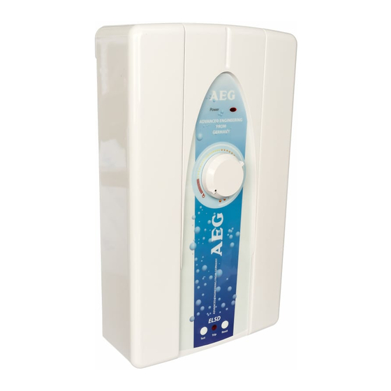
Summary of Contents for AEG BS 35
- Page 1 OPERATION AND INSTALLATION INSTRUCTIONS SHOWER WATER HEATER MODEL BS 35 / 45 / 60 BS 35 E / 45 E / 60 E...
- Page 2 This water heater must be installed (water and electrical installation), commissioned and serviced by approved service technicians in accordance with these instructions. Please read carefully Read these instruction carefully before using the appliance and retain them for future reference. If the appliance is passed on the third party please hand these instructions to the new user.
-
Page 3: Functions
1. Installation instructions for the qualitified installer Functions Fixing method Shower head level must not be higher than the unit min. 4,5 mm max. 10 mm Fig 1 Fig 3 Mounting dimensions Electrical connection The unit must be earthed ! 100 mm The cable bushing must be 105 mm... -
Page 4: Fixing, Cleaning
1. Installation instructions for the qualitified installer Fixing, cleaning Wiring Diagram a - Heating Element b - Electronic control set (Phase Cut) c - ELSD Circuit d - Triac Set e - Auto Thermostat f - ELSD-Button Board g - ELSD Sensor Coil Fig 6 Fig 5... -
Page 5: To Test
1. Installation instructions for the qualitified installer 1.1 Description of the unit Warning! The AEG BS pressureless (open) small instantaneous water heater is a device for If the Trip light activate after heating water for shower. The electrical- reset or if the light activate during shower, power is electronically controlled. -
Page 6: Technical Data
1. Installation instructions for the qualitified installer Technical Data Type 35 E 45 E 60 E Design Open outlet Rate pressure 0 MPa / 0 bar Water connection G ½“ (Extenal Thread) Electrical connection 1/N/PE/AC 220...240 V. Recomended circuit breaker 20 A. -
Page 7: Unit Structure
2. Operating instructions for the qualitified installer Unit structure Fig 7 2.1 Technical description Fig. 7 Fig. 3 1. Thermostat 10. Depth for mounting screw 2. Cable duct for electrical 11. Rear wall installation connection Fig. 5 3. Power light 12. -
Page 8: Installing The Unit
2. Operating instructions for the user and the qualitified installer 2.2 Regulations and Provisions 2.5 Installing the unit 1. Flush the cold water pipe thoroughly. Regulations of the local power 2. Fit a secure connection cable supply company must be observed. (ensure size is correct). - Page 9 2. Operating instructions for the user and the qualitified installer Handing over the unit Explain to the user how the unit works and familiarise him or her with its use. - Advise the user about possible hazards (high water temperature) - Hand over these instructions, to be kept in a safe place.
-
Page 10: Troubleshooting
3. Guarantee For guarantees please refer to the respec- The company does not accept liability tive terms and conditions of supply for for failure of any good supplied which your country. have not been installed and operated in accordance with the manufacturer’s The installation, electrical instructions. - Page 12 MATERIAL: GREEN READ PAPER 75 G. PLASTIC BAG : 7 x 11 INCH PART NO. 7901-269459 PART NAME : MANUAL BS Rev.04 Product code : BS 35 E : 221070 / BS 45 E : 221071 / BS 60 E : 221072...


