Sign In
Upload
Manuals
Brands
GE Manuals
Transducer
BAKER HUGHES DPS 5000 Series
GE BAKER HUGHES DPS 5000 Series Manuals
Manuals and User Guides for GE BAKER HUGHES DPS 5000 Series. We have
2
GE BAKER HUGHES DPS 5000 Series manuals available for free PDF download: Instruction Manual, User Manual
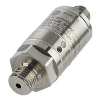
GE BAKER HUGHES DPS 5000 Series Instruction Manual (68 pages)
CAN bus Pressure Transducer
Brand:
GE
| Category:
Transducer
| Size: 0.6 MB
Table of Contents
Table of Contents
7
1 Introduction
11
Applications
11
Summary of Facilities
11
Summary of the Canopen Set of Functions
12
2 Installation
13
Example CAN Bus System
13
Installation - before Starting
13
Installation - Procedures
14
Pressure Connections (Absolute)
14
Electrical Connections
14
Completing the Installation
14
3 Operation
15
Start Operating
15
Procedures
15
Quick Start
16
Primary Objects
16
To Change the Operation - Node ID and Baud Rate
16
To Change the Operation - Objects: 0X1000 - 0X1Ffff
16
0X100C to 0X100E - Error Control: Node Guarding Option
16
0X1017 - Error Control: Heartbeat Option
16
0X1010 01 - to Save Changes to the Data Dictionary
17
0X1011 01 - to Re-Apply the Factory Values
17
0X1800 02 - the PDO Transmission (Type or Period)
17
0X1A00 - the Data in the 'Transmit PDO
17
0X1F80 - NMT Start-Up
17
To Change the Operation - Objects: 0X2000 - 0X2Ffff
18
0X210C- Node ID
18
0X210D - Bit Rate
18
0X2200 - to Change the Calibration Data
18
0X2201 to 0X2203 - the Last Calibration Year, Month, Day
18
0X2204 to 0X2206 - the Next Calibration Year, Month, Day
18
0X2207 - the Pressure Calibration Gain
19
0X2208 - the Pressure Calibration Offset
19
0X2209 - the Temperature Calibration Gain
19
0X220A - the Temperature Calibration Offset
20
0X220D to 0X2218 - the Filter System
20
0X2304 - the Tag for the Type of Data
20
To Change the Operation - Objects: 0X6000 - 0X6Ffff
20
0X6120 to 0X6124 - the Scale Data for Pressure and Temperature Output
20
0X6131 01 - the Units for the Pressure Output
21
0X6148 - the Local Limits (Minimum Pressure and Temperature)
21
0X6149 - the Local Limits (Maximum Pressure and Temperature)
21
To Monitor the Operation - Objects: 0X1000 - 0X1Ffff
22
0X1001 - the Status of the Unit
22
To Monitor the Operation - Objects: 0X2000 - 0X2Ffff
22
0X2006 - the Count: Pressure Is more than the Limit
22
0X2007 - the Count: Pressure Is Less than the Limit
22
0X2008 - the Count: Temperature Is more than the Limit
23
0X2009 - the Count: Temperature Is Less than the Limit
23
To Monitor the Operation - Objects: 0X6000 - 0X6Ffff
23
0X6130 01/0X6130 02 - the Pressure and Temperature
23
0X6150 - the Pressure and Temperature Status
23
4 Maintenance
25
Maintenance Tasks
25
Maintenance - from the Software
25
The Status of the Unit
25
Maintenance - Cleaning
26
Maintenance - Calibration
26
Calibration - Equipment
26
Two-Point Pressure Calibration - Procedure
26
Two-Point Pressure Calibration - Results
27
Approved Service Agents
27
Appendix A. Canopen Object Dictionary
29
Communication Segment
29
Object 1000H: Device Type
29
Object 1001H: Error Register
30
Object 1003H: Pre-Defined Error Field
30
Object 1005H: COB-ID SYNC
31
Object 1007H: Synchronous Window Length
31
Object 1008H: Manufacturer Device Name
31
Object 100Ch: Guard Time
32
Object 100Dh: Life Time Factor
32
Object 1010H: Store Parameter Field
33
Object 1011H: Restore Default Parameters
33
Object 1012H: COB-ID Time Stamp
34
Object 1014H: COB-ID EMCY
34
Object 1015H: Inhibit Time Emergency
35
Object 1017H: Producer Heartbeat Time
35
Object 1018H: Identity Object
36
Object 1019H: Synchronous Counter Overflow Value
37
Object 1800H to 1803H: Transmit PDO Communication Parameter
38
Object 1A00H to 1A03H: Transmit PDO Mapping Parameter
38
Object 1F80H: NMT Start-Up
40
Manufacturer Segment
40
Object 2003H: Current Time
40
Object 2004H: Acquisition Time
41
Object 2005H: Acquisition Interval
41
Object 2006H: Pressure Span Overflow Count
41
Object 2007H: Pressure Span Underflow Count
42
Object 2008H: Temperature Span Overflow Count
42
Object 2009H: Temperature Span Underflow Count
42
Object 210Ch: Node ID
43
Object 210Dh: Bit Rate
43
Object 2200H: Calibration Access Pin
43
Object 2201H: Last Calibration Year
44
Object 2202H: Last Calibration Month
44
Object 2203H: Last Calibration Day
44
Object 2204H: Next Calibration Year
45
Object 2205H: Next Calibration Month
45
Object 2206H: Next Calibration Day
45
Object 2207H: Pressure Gain
46
Object 2208H: Pressure Offset
46
Object 2209H: Temperature Gain
46
Object 220Ah: Temperature Offset
47
Object 220Dh: FIR Samples Size
47
Object 220Eh: FIR Sample Data
47
Object 2210H: FIR2 Sample Data
48
Object 2212H: FIR3 Sample Data
48
Object 2214H: FIR4 Sample Data
48
Object 2216H: FIR5 Sample Data
49
Object 2217H: Selected FIR Filter
49
Object 2218H: FIR Pre-Scaler
49
Object 2300H: PDCR Min Pressure
51
Object 2301H: PDCR Max Pressure
51
Object 2302H: PDCR Type
51
Object 2304H: PDCR Text
51
Device Profile Segment
52
Object 6100H: AI Input FV
52
Object 6101H: AI Input Unit
53
Object 6110H: AI Sensor Type
53
Object 6120H: AI Input Scaling 1 FV
54
Object 6121H: AI Input Scaling 1 PV
55
Object 6122H: AI Input Scaling 2 FV
56
Object 6123H: AI Input Scaling 2 PV
56
Object 6124H: AI Input Offset
57
Object 6130H: AI Input PV
58
Object 6131H: AI Physical Unit PV
59
Object 6148H: AI Span Start
60
Object 6149H: AI Span End
60
Object 6150H: AI Status
61
Appendix B. Alternative Pressure Units
63
Appendix C. Bibliography
65
Advertisement
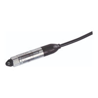
GE BAKER HUGHES DPS 5000 Series User Manual (36 pages)
I2C-bus Pressure Transducer
Brand:
GE
| Category:
Accessories
| Size: 0.43 MB
Table of Contents
Table of Contents
6
Introduction
9
General
9
Configuration
9
Figure 1 External and Internal DPS 5000 Sensors - General View
9
Installation
10
General
10
Mounting and Orientation
10
Connecting to the Pressure Source
10
Electrical Connections
11
Figure 2 Pressure Connection
11
Figure 3 Typical I 2 C-Bus Network
11
Functional Description
12
Sensor Communication
12
Figure 4 Typical I 2 C-Bus Data Transfers
12
Table 1 Electrical Connections
12
Table 2 I 2 C-Bus Feature Support
12
Memory Map
13
Register Descriptions
13
Register Bit Table Legend
13
Table 3 Memory Map
13
Address 0 - STATUS
14
Figure 5 Bit Table Legend
14
Address 1 - COMP_PRES
15
Address 2 - COMP_TEMP
16
Address 3 - ADC_PRES
16
Address 4 - ADC_TEMP
17
Address 5 - ACCESS
17
Address 6 - MVOLT_PRES
17
Address 7 - MVOLT_TEMP
18
Address 66 - I2C_ADDR
18
Address 67 - COEF_FIT
19
Address 68 - GAIN_ADJ
19
Address 69 - OFFSET_ADJ
20
Address 70 - MAX_RANGE
20
Address 71 - MIN_RANGE
20
Address 72 - CAL_DATE
21
Address 73 - MAX_ADC_PRES
21
Address 74 - MIN_ADC_PRES
22
Address 75 - MAX_ADC_TEMP
22
Address 76 - MIN_ADC_TEMP
22
Address 77 - SERIAL
23
Address 78 - CONFIG
23
Address 79 - VERSION
24
Address 82 - AVERAGE
24
Address 83 - PRES_CONV
25
Address 84 - PRES_UNIT
25
Address 85 - DELAY
26
Address 86 - SPEC_DWG
27
Address 87 - TARE_VALUE
27
Addresses 128-157 - Pressure Coefficients
27
Addresses 158-187 - Temperature Coefficients
28
Operational Description
28
Operational States
28
Figure 6 Operational States
28
Reading the Pressure and Temperature
29
Updating the Pressure and Temperature
29
Manual Update
29
Figure 7 Interaction Legend
29
Automatic Update
30
Updating the Sensor Configuration Data Registers
30
User Modifiable Registers
30
Table 4 User Modifiable Registers
30
Modifying the I 2 C-Bus Address
31
Changing the Auto-Update Period
31
Changing the Unit of Pressure
32
Reading Relative Pressure
32
Pressure and Temperature SNR
33
Figure 8 Noise Level Correction Factors
33
Maximising the Update Rate
34
Pressure Re-Calibration
34
Maintenance
35
Cleaning
35
Adjustment
36
Repair
36
Disposal
36
Advertisement
Related Products
GE Profile DPSB513
GE Profile DPSE810EG
GE Profile DPSE810
GE DPSQ495ET
GE DPSQ495GT
GE DPSB613GD
GE Profile DPSB620GCWW
GE Profile DPSE810GG
GE DPSR610EGWT - Profile 7.0 cu. Ft. Electric Dryer
GE DPSR610GGWT - Profile 7.0 cu. Ft. Gas Dryer
GE Categories
Refrigerator
Ranges
Microwave Oven
Air Conditioner
Dishwasher
More GE Manuals
Login
Sign In
OR
Sign in with Facebook
Sign in with Google
Upload manual
Upload from disk
Upload from URL