Table of Contents
Advertisement
SERVICE MANUAL
Ver. 1.0 2008.11
• The tuner and CD sections have no adjustments.
CD player section
Signal-to-noise ratio: 120 dB
Frequency response: 10 – 20,000 Hz
Wow and fl utter: Below measurable limit
Tuner section
FM
Tuning range:
87.5 – 108.0 MHz (at 50 kHz step)
87.5 – 107.9 MHz (at 200 kHz step)
FM tuning interval: 50 kHz/200 kHz switchable
Antenna (aerial) terminal:
External antenna (aerial) connector
Intermediate frequency: 150 kHz
Usable sensitivity: 10 dBf
Selectivity: 75 dB at 400 kHz
Signal-to-noise ratio: 70 dB (mono)
Separation: 40 dB at 1 kHz
Frequency response: 20 – 15,000 Hz
AM
Tuning range:
531 – 1,602 kHz (at 9 kHz step)
530 – 1,710 kHz (at 10 kHz step)
AM tuning interval: 9 kHz/10 kHz switchable
Antenna (aerial) terminal:
External antenna (aerial) connector
Intermediate frequency: 25 kHz
Sensitivity: 26 μV
Sony Corporation
9-889-365-01
2008K04-1
Audio&Video Business Group
©
2008.11
Published by Sony Techno Create Corporation
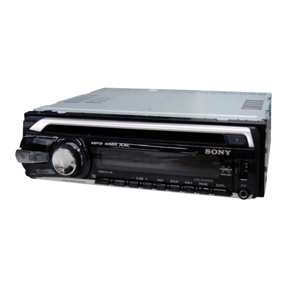
CDX-GT48UM/GT480U/
Photo: CDX-GT480US
Model Name Using Similar Mechanism
CD Drive Mechanism Type
Optical Pick-up Name
SPECIFICATIONS
USB Player section
Interface: USB (Full-speed)
Maximum current: 500 mA
Power amplifi er section
Outputs: Speaker outputs (sure seal connectors)
Speaker impedance: 4 – 8 ohms
Maximum power output: 52 W × 4 (at 4 ohms)
General
Outputs:
Audio outputs terminal
(front, sub/rear switchable)
Power antenna (aerial) relay control terminal
Power amplifi er control terminal
Inputs:
Remote controller input terminal
Antenna (aerial) input terminal
AUX input jack (stereo mini jack)
USB signal input terminal
FM/AM COMPACT DISC PLAYER
GT480US/GT484US
CDX-GT480U/GT480US
Indian Model
CDX-GT48UM/GT484US
NEW
MG-101Y-188//C
DAX-25A
Tone controls:
Low: ±10 dB at 60 Hz (XPLOD)
Mid: ±10 dB at 1 kHz (XPLOD)
High: ±10 dB at 10 kHz (XPLOD)
Power requirements: 12 V DC car battery
(negative ground (earth))
Power supply voltage: 11 – 16 V
Dimensions: Approx. 178 × 50 × 179 mm
1
1
(7
/
× 2 × 7
/
in.) (w/h/d)
8
8
Mounting dimensions:
Approx. 182 × 53 × 162 mm
1
1
1
(7
/
× 2
/
× 6
/
in.) (w/h/d)
4
8
2
Mass: Approx. 1.2 kg (2 lb. 11 oz.)
Supplied accessories:
Card remote commander: RM-X151
Parts for installation and connections (1 set)
Design and specifi cations are subject to change
without notice.
E Model
Advertisement
Table of Contents

Related Manuals for Sony CDX-GT48UM


Summary of Contents for Sony CDX-GT48UM
- Page 1 AM tuning interval: 9 kHz/10 kHz switchable Antenna (aerial) terminal: External antenna (aerial) connector Intermediate frequency: 25 kHz Sensitivity: 26 μV FM/AM COMPACT DISC PLAYER Sony Corporation 9-889-365-01 2008K04-1 Audio&Video Business Group © 2008.11 Published by Sony Techno Create Corporation...
- Page 2 COMPONENTS IDENTIFIED BY MARK 0 OR DOTTED LINE WITH MARK 0 ON THE SCHEMATIC DIAGRAMS AND IN THE PARTS LIST ARE CRITICAL TO SAFE OPERATION. REPLACE THESE COMPONENTS WITH SONY PARTS WHOSE PART NUMBERS APPEAR AS SHOWN IN THIS MANUAL OR IN SUPPLEMENTS PUBLISHED BY SONY.
-
Page 3: Table Of Contents
CDX-GT48UM/GT480U/GT480US/GT484US This compact disc player is classifi ed as a CLASS 1 LASER TABLE OF CONTENTS product. The CLASS 1 LASER PRODUCT label is located on the exterior. SERVICE NOTE ............GENERAL Location of Controls ............Connections ..............DISASSEMBLY This label is located on the bottom of the chassis. -
Page 4: Service Note
CDX-GT48UM/GT480U/GT480US/GT484US SECTION 1 SERVICE NOTE EXTENSION CABLE AND SERVICE POSITION When repairing or servicing this set, connect the jig (extension cable) as shown below. • Connect the MAIN board (CN701) and the SERVO board (CN401) with the extension cable (Part No. J-2502-076-1). -
Page 5: General
CDX-GT48UM/GT480U/GT480US/GT484US SECTION 2 This section is extracted GENERAL from instruction manual. • LOCATION OF CONTROLS Location of controls and basic operations Main unit SEEK +/– buttons The following buttons on the card remote commander have also different buttons/functions CD/USB: from the unit. Remove the insulation film before To skip tracks (press);... -
Page 6: Connections
CDX-GT48UM/GT480U/GT480US/GT484US • CONNECTION • Except CDX-GT480US: Argentina model FRONT REMOTE AUDIO OUT from car antenna (aerial) REAR/SUB FRONT desde la antena del automóvil AUDIO OUT REAR / SUB Fuse (10 A) Fusible (10 A) AUDIO OUT RCA pin cord (not supplied) -
Page 7: Connection Diagram
CDX-GT48UM/GT480U/GT480US/GT484US • CONNECTION • CDX-GT480US: Argentina model Speaker, Rear, Right Altavoz, posterior, derecho Purple Morado Speaker, Rear, Right – Altavoz, posterior, derecho Speaker, Front, Right Altavoz, frontal, derecho Gray Gris FRONT REMOTE Speaker, Front, Right – Altavoz, frontal, derecho AUDIO OUT... -
Page 8: Disassembly
CDX-GT48UM/GT480U/GT480US/GT484US SECTION 3 DISASSEMBLY • This set can be disassembled in the order shown below. 3-1. SUB PANEL ASSY (Page 9) 3-2. CD MECHANISM BLOCK (Page 9) 3-4. SERVO BOARD 3-3. MAIN BOARD (Page 10) (Page 10) 3-5. CHASSIS (T) SUB ASSY (Page 11) 3-6. -
Page 9: Sub Panel Assy
CDX-GT48UM/GT480U/GT480US/GT484US Note: Follow the disassembly procedure in the numerical order shown below. 3-1. SUB PANEL ASSY two claws two claws two screws (+PTT 2.6 × 6) sub panel assy 3-2. CD MECHANISM BLOCK bracket (CD) CD mechanism block two screws (+PTT 2.6 ×... -
Page 10: Main Board
CDX-GT48UM/GT480U/GT480US/GT484US 3-3. MAIN BOARD two screws two screws (+PTT 2.6 × 8) (+P 2.6 × 8) two screws (+PTT 2.6 × 10) three screws screw (+BTT) (+P 2.6 × 10) screw (+PTT 2.6 × 10) heat sink MAIN board insulating sheet 3-4. -
Page 11: Chassis (T) Sub Assy
CDX-GT48UM/GT480U/GT480US/GT484US 3-5. CHASSIS (T) SUB ASSY two precision screws two precision screws (+P 1.7 × 2.2) (+P 1.7 × 2.2) chassis (T) sub assy claw 3-6. ROLLER ARM ASSY roller arm assy gear (RA1) spring (RAL) washer spring (RAR) -
Page 12: Chassis (Op) Assy
CDX-GT48UM/GT480U/GT480US/GT484US 3-7. CHASSIS (OP) ASSY chassis (OP) assy tension spring (KF) two coil springs (damper) (natural) coil spring (damper) (green) slider (R) lever (D) gear (LE1) 3-8. CHUCKING ARM SUB ASSY chucking arm sub assy spring Note: Have this portion receive the chassis. -
Page 13: Sled Motor Assy
CDX-GT48UM/GT480U/GT480US/GT484US 3-9. SLED MOTOR ASSY three serration screws (M 2 × 3) sled motor assy spring turn table spring stand Note: Never remove these parts since they were adjusted. bearing (F) stand Note: Place the stand with care not to touch the turn table. -
Page 14: 3-10. Optical Pick-Up Section
CDX-GT48UM/GT480U/GT480US/GT484US 3-10. OPTICAL PICK-UP SECTION optical pick-up section Note: Be careful not to touch the lens and hologram terminal when removing the optical pick-up section. 3-11. OPTICAL PICK-UP pan tapping screw (M 1.4 × 3.5) leaf spring (sub guide) leaf spring (OP) -
Page 15: Diagrams
CDX-GT48UM/GT480U/GT480US/GT484US SECTION 4 DIAGRAMS 4-1. BLOCK DIAGRAM – MAIN Section – ELECTRONIC VOLUME IC302 R/S OUT-L REAR/SUB R/S OUT-R R-CH (REAR/SUB) J302 R-CH AUDIO R-CH ZAPPIN1 J901 I2C BUS CONTROLLED FRONT MUTE 7 AUX-L ZAPPIN2 R-CH POWER AMP/MULTIPLE Q102 R-CH... -
Page 16: Block Diagram -Display Section
CDX-GT48UM/GT480U/GT480US/GT484US 4-2. BLOCK DIAGRAM – DISPLAY Section – SYSTEM CONTROL LCD DRIVER,LED CONTROL IC401 (2/2) IC901 SEG48 KEYIN1 KEY MATRIX LCD901 LSW901,905–913, • LCD_SO DATA SEG1 LIQUID PANEL+B S902–908 KEYIN0 • LCD_SCK CLK LCD CRYSTAL DISPLAY LCD_CE LED926-929 (GT48UM) LED907,911,913-915,... - Page 17 CDX-GT48UM/GT480U/GT480US/GT484US THIS NOTE IS COMMON FOR PRINTED WIRING BOARDS AND SCHEMATIC DIAGRAMS. • Waveforms – MAIN Board – (In addition to this, the necessary note is printed in each block.) For Printed Wiring Boards: For Schematic Diagrams: Note: Note: IC001 (XTAL1) •...
-
Page 18: Printed Wiring Board -Main Section
CDX-GT48UM/GT480U/GT480US/GT484US 4-3. PRINTED WIRING BOARD – MAIN Section – • : Uses unleaded solder. J302 AUDIO OUT REAR/SUB FRONT GT480U/GT480US:E,MX MODEL/GT484US J801 (REMOTE IN) C115 C215 CN802 R829 C114 C214 C107 C304 JW220 C315 R826 C405 C207 C113 C213 FU601... -
Page 19: Schematic Diagram -Main Section (1/3)
CDX-GT48UM/GT480U/GT480US/GT484US 4-4. SCHEMATIC DIAGRAM – MAIN Section (1/3) – • See page 24 for IC Block Diagrams. GT480U/GT480US:E,MX MODEL/GT484US MAIN BOARD (1/3) IC B/D IC301 FRONT L-CH – I2C BUS CONTROLLED POWER AMP/MULTIPLE REAR VOLTAGE REGULATOR L-CH – IC301 REAR... -
Page 20: Schematic Diagram -Main Section (2/3)
CDX-GT48UM/GT480U/GT480US/GT484US 4-5. SCHEMATIC DIAGRAM – MAIN Section (2/3) – • See page 17 for waveforms. • See page 24 for IC Block Diagrams. MAIN BOARD (2/3) C213 100p J302 C113 100p FRONT IC B/D C207 100p AUDIO OUT IC001 R829... -
Page 21: Schematic Diagram -Main Section (3/3)
CDX-GT48UM/GT480U/GT480US/GT484US 4-6. SCHEMATIC DIAGRAM – MAIN Section (3/3) – • See page 17 for Waveforms. • See page 26 for IC Block Diagrams. • See page 27 for IC Pin Function Description. (Page 19) MAIN BOARD (1/3) MAIN BOARD (3/3) -
Page 22: Printed Wiring Boards -Key Section
LED914 B-2 <LED927> C-5 (D908) G-10 IC902 LED915 C-1 LED928 B-4 (Q901) (D909) G-10 LED918 C-2 <LED929> C-3 (Q902) (D910) G-10 LED901 C-12 LED922 B-7 LED930 C-2 (Q907) ) : SIDE B < > : CDX-GT48UM only ] : CDX-GT480U/GT480US/GT484US CDX-GT48UM/GT480U/GT480US/GT484US... -
Page 23: Schematic Diagram -Key Section
CDX-GT48UM/GT480U/GT480US/GT484US 4-8. SCHEMATIC DIAGRAM – KEY Section – KEY BOARD R907 LED901 NESW505CT-AST LED907,911,913-915,918,922,924,925,928,930,931 (LCD BACK LIGHT) SML-310DTT86 (GT48UM) R906 R905 SML-310VTT86 (GT480U/GT480US/GT484US) IC902 R908 IC902 RS-470 R909 REMOTE CONTROL R935 SIGNAL RECEIVER GND1 R910 LSW905 GND2 LSW901 S[4] S[21]... - Page 24 CDX-GT48UM/GT480U/GT480US/GT484US • IC Block Diagrams IC301 TDA8588AJ/N2/R1 (MAIN Board (1/3)) IC001 TEF6607T/V4/S470,518 (MAIN Board (2/3)) AMRFIN 1 AMSELOUT2 I2C_SIO AMSELOUT1 OUT-FL– C BUS AMRFDEC 2 TUNER AMIFAGC1 I2C_SCK FMIN2 3 AMSELIN2 OUT-FL+ TUNER FMIN1 4 AMSELIN1 OUT-RL– GNDRF 5 P-GND1...
- Page 25 CDX-GT48UM/GT480U/GT480US/GT484US IC302 BD3447AFV-E2 (MAIN Board (2/3)) I2C BUS LOGIC, FADER FADER FADER FADER FADER EFFECT 180 /0 7 BAND 3 BAND P-EQ (TONE CONTROL) SPECTRUM ANALYZER /LEVEL METER VOLUME/MUTE SPEANA LVL METER LVL METER SPEANA INPUT GAIN INPUT SELECTOR (3 SIGLE-END AND 3 STEREO IS O)
- Page 26 CDX-GT48UM/GT480U/GT480US/GT484US IC501 TPS40200DRG4 (MAIN Board (3/3)) UVLO ISNS DRIVER LOGIC E/A AND SS REFERENCE SOFT-START OVERCURRENT 700mV COMP ENABLE E/A IC502 TC7WH123FU(TE12R) (MAIN Board (3/3)) RX/CX IC503 NJM2387ADL3(TE2) (MAIN Board (3/3)) CURRENT LIMIT OVERVOLTAGE THERMAL PROTECTION PROTECTION BANDGAP REFERENCE CONT...
- Page 27 Power supply pin (+3.3 V) Ground Regulator reference capacitor connecting pin UNISI SONY-BUS data input (Fixed at L in this set) UNISO SONY-BUS data output (Not used in this set) UNISCK SONY-BUS clock signal output (Not used in this set)
- Page 28 CDX-GT48UM/GT480U/GT480US/GT484US Pin No. Pin Name Description WAKE_UP CD mechanism deck micon wake up signal output MC_RX MC-BUS communication and CD mechanism deck micon communication RX input MC_TX MC-BUS communication and CD mechanism deck micon communication TX output CLK_IN Flash programming serial clock signal input...
-
Page 29: Exploded Views
CDX-GT48UM/GT480U/GT480US/GT484US SECTION 5 EXPLODED VIEWS Note: • -XX and -X mean standardized parts, so • The mechanical parts with no reference The components identifi ed by mark 0 they may have some difference from the number in the exploded views are not sup- or dotted line with mark 0 are critical for original one. -
Page 30: Front Panel Section
CDX-GT48UM/GT480U/GT480US/GT484US 5-2. FRONT PANEL SECTION not supplied (KEY board) RE901 not supplied not supplied (JACK board) not supplied CN902 LCD901 not supplied not supplied not supplied not supplied not supplied Ref. No. Part No. Description Remark Ref. No. Part No. -
Page 31: Cd Mechanism Section (Mg-101Y-188//C)
CDX-GT48UM/GT480U/GT480US/GT484US 5-3. CD MECHANISM SECTION (MG-101Y-188//C) not supplied not supplied not supplied not supplied not supplied not supplied not supplied not supplied not supplied not supplied not supplied not supplied Ref. No. Part No. Description Remark Ref. No. Part No. -
Page 32: Electrical Parts List
CDX-GT48UM/GT480U/GT480US/GT484US SECTION 6 JACK ELECTRICAL PARTS LIST Note: • Due to standardization, replacements in • COILS When indicating parts by reference num- the parts list may be different from the uH: μH ber, please include the board name. parts specifi ed in the diagrams or the com- •... - Page 33 CDX-GT48UM/GT480U/GT480US/GT484US Ref. No. Part No. Description Remark Ref. No. Part No. Description Remark LED931 8-719-053-08 LED SML-310DTT86 (m . /SEEK–) R921 1-216-821-11 METAL CHIP 1/10W (GT48UM) R922 1-216-821-11 METAL CHIP 1/10W LED931 8-719-053-09 LED SML-310VTT86 (m . /SEEK–) R923 1-216-822-11 METAL CHIP 1.2K...
- Page 34 CDX-GT48UM/GT480U/GT480US/GT484US MAIN Ref. No. Part No. Description Remark Ref. No. Part No. Description Remark < ROTARY ENCODER > C113 1-163-251-11 CERAMIC CHIP 100PF C114 1-165-908-11 CERAMIC CHIP 1uF RE901 1-479-902-32 ENCODER, ROTARY C115 1-165-908-11 CERAMIC CHIP 1uF (PUSH ENTER/SELECT (VOLUME))
- Page 35 CDX-GT48UM/GT480U/GT480US/GT484US MAIN Ref. No. Part No. Description Remark Ref. No. Part No. Description Remark C427 1-162-964-11 CERAMIC CHIP 0.001uF D303 6-500-522-01 DIODE 10EDB40-TA1B2 C428 1-162-964-11 CERAMIC CHIP 0.001uF D304 6-500-522-01 DIODE 10EDB40-TA1B2 C429 1-162-970-11 CERAMIC CHIP 0.01uF D305 6-500-522-01 DIODE 10EDB40-TA1B2...
- Page 36 CDX-GT48UM/GT480U/GT480US/GT484US MAIN Ref. No. Part No. Description Remark Ref. No. Part No. Description Remark JC103 1-216-296-11 SHORT CHIP Q505 8-729-027-43 TRANSISTOR DTC114EKA-T146 JC104 1-216-296-11 SHORT CHIP Q701 8-729-027-43 TRANSISTOR DTC114EKA-T146 JC105 1-216-295-11 SHORT CHIP Q802 8-729-027-43 TRANSISTOR DTC114EKA-T146 JC106 1-216-864-11...
- Page 37 CDX-GT48UM/GT480U/GT480US/GT484US MAIN SERVO Ref. No. Part No. Description Remark Ref. No. Part No. Description Remark R419 1-216-845-11 METAL CHIP 100K 1/10W R523 1-216-821-11 METAL CHIP 1/10W R420 1-216-809-11 METAL CHIP 1/10W R524 1-216-821-11 METAL CHIP 1/10W R421 1-216-833-11 METAL CHIP...
- Page 38 CDX-GT48UM/GT480U/GT480US/GT484US Ref. No. Part No. Description Remark ACCESSORIES ************ 1-479-077-13 REMOTE COMMANDER (RM-X151) 2-548-729-01 LID, BATTERY CASE (for RM-X151) 4-109-735-31 MANUAL, INSTRUCTION (ENGLISH,SPANISH, PERSIAN) 4-109-736-31 MANUAL, INSTRUCTION, INSTALL (ENGLISH, SPANISH,PERSIAN) (EXCEPT GT480US:AR) 4-109-736-51 MANUAL, INSTRUCTION, INSTALL (ENGLISH, SPANISH) (GT480US:AR) X-2186-697-1...
- Page 39 CDX-GT48UM/GT480U/GT480US/GT484US MEMO...
- Page 40 CDX-GT48UM/GT480U/GT480US/GT484US REVISION HISTORY Checking the version allows you to jump to the revised page. Also, clicking the version at the top of the revised page allows you to jump to the next revised page. Ver. Date Description of Revision 2008.11...