Sony CDX-GT42IPW Service Manual
Fm/mw/lw compact disc player
Hide thumbs
Also See for CDX-GT42IPW:
- Operating instructions manual (36 pages) ,
- Installation/connections (2 pages) ,
- Limited warranty (1 page)
Table of Contents
Advertisement
SERVICE MANUAL
Ver. 1.0 2007. 08
• The tuner and CD sections have no adjustments.
AUDIO POWER SPECIFICATIONS (CDX-GT42IPW/GT420IP)
POWER OUTPUT AND TOTAL HARMONIC DISTORTION
23.2 watts per channel minimum continuous average power into
4 ohms, 4 channels driven from 20 Hz to 20 kHz with no more
than 5% total harmonic distortion.
CD player section
Signal-to-noise ratio
120 dB
Frequency response
10 – 20,000 Hz
Wow and flutter
Below measurable limit
Tuner section
FM
Tuning range
CDX-GT42IPW/GT420IP:
87.5 – 107.9 MHz
CDX-GT44IP:
87.5 – 108.0 MHz
Antenna terminal
External antenna connector
Intermediate frequency 10.7 MHz/450 kHz
Usable sensitivity
9 dBf
Selectivity
75 dB at 400 kHz
Signal-to-noise ratio
67 dB (stereo), 69 dB (mono)
Harmonic distortion at 1 kHz
0.5% (stereo), 0.3% (mono)
Separation
35 dB at 1 kHz
Frequency response
30 – 15,000 Hz
Sony Corporation
9-887-813-01
eVehicle Division
2007H04-1
Published by Sony Techno Create Corporation
© 2007. 08
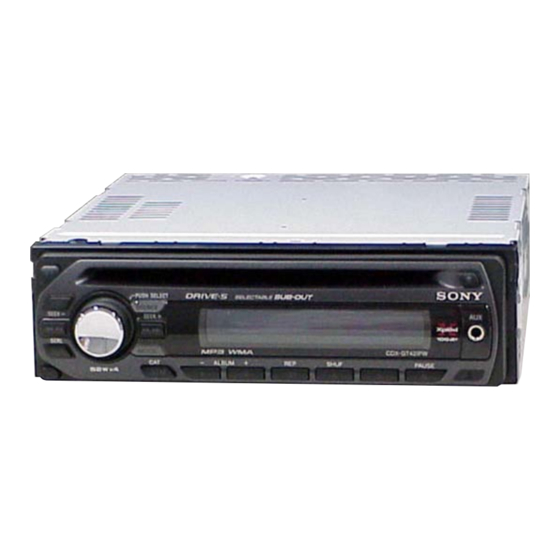
CDX-GT42IPW/GT44IP/
(Photo: CDX-GT42IPW)
Model Name Using Similar Mechanism
CD Drive Mechanism Type
Optical Pick-up Name
SPECIFICATIONS
AM (CDX-GT42IPW/GT420IP)
Tuning range
Antenna terminal
Intermediate frequency 10.7 MHz/450 kHz
Sensitivity
MW/LW (CDX-GT44IP)
Tuning range
Antenna terminal
Intermediate frequency 10.7 MHz/450 kHz
Sensitivity
FM/AM COMPACT DISC PLAYER
FM/MW/LW COMPACT DISC PLAYER
GT420IP
US Model
CDX-GT42IPW/GT420IP
AEP Model
UK Model
CDX-GT44IP
CDX-GT22W/GT120/GT220
MG-101TC-188//C
DAX-25A
530 – 1,710 kHz
External antenna connector
30 µV
MW: 531 – 1,602 kHz
LW: 153 – 279 kHz
External antenna connector
MW: 30 µV, LW: 40 µV
– Continued on next page –
CDX-GT42IPW/GT420IP
CDX-GT44IP
Advertisement
Table of Contents

Related Manuals for Sony CDX-GT42IPW


Summary of Contents for Sony CDX-GT42IPW
- Page 1 0.5% (stereo), 0.3% (mono) Separation 35 dB at 1 kHz Frequency response 30 – 15,000 Hz FM/AM COMPACT DISC PLAYER CDX-GT42IPW/GT420IP FM/MW/LW COMPACT DISC PLAYER CDX-GT44IP Sony Corporation 9-887-813-01 eVehicle Division 2007H04-1 Published by Sony Techno Create Corporation © 2007. 08...
- Page 2 COMPONENTS IDENTIFIED BY MARK 0 OR DOTTED LINE WITH MARK 0 ON THE SCHEMATIC DIAGRAMS AND IN THE PARTS LIST ARE CRITICAL TO SAFE OPERATION. REPLACE THESE COMPONENTS WITH SONY PARTS WHOSE PART NUMBERS APPEAR AS SHOWN IN THIS MANUAL OR IN SUPPLEMENTS PUBLISHED BY SONY.
-
Page 3: Table Of Contents
SERVICE NOTE ............4 • CDX-GT44IP GENERAL Location of Controls (CDX-GT42IPW) ......5 Connections (CDX-GT42IPW) ........5 Location of Controls (CDX-GT44IP) ......7 Connections (CDX-GT44IP) ........... 7 Location of Controls (CDX-GT420IP) ......9 This label is located on the bottom of the chassis. -
Page 4: Service Note
CDX-GT42IPW/GT44IP/GT420IP SECTION 1 SERVICE NOTE EXTENSION CABLE AND SERVICE POSITION When repairing or servicing this set, connect the jig (extension cable) as shown below. • Connect the MAIN board (CN350) and the SERVO board (CN2) with the extension cable (Part No. J-2502-076-1). -
Page 5: General
CDX-GT42IPW/GT44IP/GT420IP SECTION 2 GENERAL This section is extracted from instruction manual. • LOCATION OF CONTROL (CDX-GT42IPW) Location of controls and basic operations Main unit J DSPL (display)/SCRL (scroll) button The following buttons on the card remote commander have also different buttons/functions page 8 from the unit. -
Page 6: Connection Diagram
CDX-GT42IPW/GT44IP/GT420IP RCA pin cord (not supplied) AUDIO OUT can be switched SUB or REAR. For details, see the supplied Operating Instructions. Cable con terminales RCA (no suministrado) AUDIO OUT (salida de audio) puede cambiarse a SUB (secundaria) o REAR (posterior). Para obtener información, consulte el manual de instrucciones suministrado. -
Page 7: Location Of Controls (Cdx-Gt44Ip)
CDX-GT42IPW/GT44IP/GT420IP • LOCATION OF CONTROL (CDX-GT44IP) Location of controls and basic operations Main unit J DSPL (display)/SCRL (scroll) button The following buttons on the card remote commander have also different buttons/functions page 8, 9 from the unit. Remove the insulation film before To change display items (press);... -
Page 8: Connection Diagram
CDX-GT42IPW/GT44IP/GT420IP Note for the antenna (aerial) connecting Remarque sur le raccordement de Opmerking bij de antenne-aansluiting If your car antenna (aerial) is an l’antenne Indien uw auto is uitgerust met een ISO (International Organization for Si votre antenne de voiture est de type... -
Page 9: Location Of Controls (Cdx-Gt420Ip)
CDX-GT42IPW/GT44IP/GT420IP • LOCATION OF CONTROL (CDX-GT420IP) Location of controls and basic operations Main unit J DSPL (display)/SCRL (scroll) button The following buttons on the card remote commander have also different buttons/functions page 8 from the unit. Remove the insulation film before To change display items (press);... - Page 10 CDX-GT42IPW/GT44IP/GT420IP RCA pin cord (not supplied) AUDIO OUT can be switched SUB or REAR. For details, see the supplied Operating Instructions. Cordon à broche RCA (non fourni) AUDIO OUT peut être commuté sur SUB ou REAR. Pour obtenir plus de détails, reportez-vous au mode d’emploi fourni.
-
Page 11: Disassembly
CDX-GT42IPW/GT44IP/GT420IP SECTION 3 DISASSEMBLY Note: This set can be disassemble according to the following sequence. 3-1. SUB PANEL ASSY (Page 12) 3-2. CD MECHANISM BLOCK (Page 12) 3-4. SERVO BOARD 3-3. MAIN BOARD (Page 13) (Page 13) 3-5. CHASSIS (T) SUB ASSY (Page 14) 3-6. -
Page 12: Sub Panel Assy
CDX-GT42IPW/GT44IP/GT420IP Note: Follow the disassembly procedure in the numerical order given. 3-1. SUB PANEL ASSY 3 two claws 2 two claws 1 two screws (+PTT 2.6 × 6) 4 sub panel assy 3-2. CD MECHANISM BLOCK 6 bracket (CD) 7 CD mechanism block 5 two screws (+PTT 2.6 ×... -
Page 13: Main Board
CDX-GT42IPW/GT44IP/GT420IP 3-3. MAIN BOARD 8 two screws 9 two screws 2 two screws (+P 2.6 × 8) (+PTT 2.6 × 10) (+PTT 2.6 × 8) 0 screw 1 three ground point screws (+P 2.6 × 10) (+PTT 2.6 × 6) 6 screw (+PTT 2.6 ×... -
Page 14: Chassis (T) Sub Assy
CDX-GT42IPW/GT44IP/GT420IP 3-5. CHASSIS (T) SUB ASSY 2 two precision screws 1 two precision screws (+P 1.7 × 2.2) (+P 1.7 × 2.2) 4 chassis (T) sub assy 3 claw 3-6. ROLLER ARM ASSY 5 roller arm assy 4 gear (RA1) -
Page 15: Chassis (Op) Assy
CDX-GT42IPW/GT44IP/GT420IP 3-7. CHASSIS (OP) ASSY 6 chassis (OP) assy 1 tension spring (KF) 7 coil spring (damper) (natural) 8 coil spring (damper) (black) 4 slider (R) 3 lever (D) 2 gear (LE1) 3-8. CHUCKING ARM SUB ASSY 3 chucking arm sub assy 1 spring Note: Have this portion receive the chassis. -
Page 16: Sled Motor Assy
CDX-GT42IPW/GT44IP/GT420IP 3-9. SLED MOTOR ASSY 2 three serration screws (M 2 × 3) 3 sled mtor assy 1 spring turn table spring stand Note: Never remove these parts since they were adjusted. stand Note: Place the stand with care not to touch the turn table. -
Page 17: Optical Pick-Up Section
CDX-GT42IPW/GT44IP/GT420IP 3-10. OPTICAL PICK-UP SECTION 2 optical pick-up section Note: Be careful not to touch the lens and hologram terminal when removing the optical pick-up section. 3-11. OPTICAL PICK-UP 1 pan tapping screw (M 1.4 × 2.5) 2 leaf spring (sub guide) -
Page 18: Diagnosis Function
CDX-GT42IPW/GT44IP/GT420IP SECTION 4 DIAGNOSIS FUNCTION Description of the Diagnostics function: 4. Contents of each display mode 4-1. Reset count display mode 1. Setting the Diag display mode With the power off, press the [4] button, [5] button, and [4] button on the set body or the remote control (for more than 2 seconds) in turn. - Page 19 CDX-GT42IPW/GT44IP/GT420IP 4-5. CD error information display mode 4-6. OFFSET/FAILURE error display mode 4-5-1. Error description 0 6 1 X X X X X 0 5 1 Operating hours Error information Error description Error description Indication Description (in hexadecimal (0: OFFSET, 1: FAILURE)
- Page 20 CDX-GT42IPW/GT44IP/GT420IP MEMO...
-
Page 21: Diagrams
CDX-GT42IPW/GT44IP/GT420IP SECTION 5 DIAGRAMS 5-1. BLOCK DIAGRAM — MAIN SECTION — ELECTRONIC VOLUME IC401 AUX/IPOD SELECT SUBOUT L SWITCH IPOD–AUD-L REAR (IPOD IN) R–CH SUBOUT R J652 IC210 R-CH IPOD–AUD–R R–CH AUDIO (1/2) IPOD–AUD–GND 9 AUX–LCH MUTE R–CH 7 AUX–RCH... -
Page 22: Block Diagram -Display Section
CDX-GT42IPW/GT44IP/GT420IP 5-2. BLOCK DIAGRAM — DISPLAY SECTION — • NOTE FOR PRINTED WIRING BOARDS AND SCHEMATIC DIAGRAMS THIS NOTE IS COMMON FOR PRINTED WIRING BOARDS AND SCHEMATIC DIAGRAMS. SYSTEM CONTROL DISPLAY CONTROL (In addition to this, the necessary note is... -
Page 23: Printed Wiring Board -Main Section
CDX-GT42IPW/GT44IP/GT420IP 5-3. PRINTED WIRING BOARD — MAIN SECTION — : Uses unleaded solder. J652 GT42IPW /GT420IP CDX-GT42IPW/GT420IP C443 C445 JC31 JC29 JC30 CN300 R445 R450 C330 C325 F901 R423 JW50 C432 R449 C423 C426 JW51 C452 JC13 C307 C304 C301... -
Page 24: Schematic Diagram -Main Section (1/4)
CDX-GT42IPW/GT44IP/GT420IP 5-4. SCHEMATIC DIAGRAM — MAIN SECTION (1/4) — • Refer to page 32 for IC Block Diagrams. R302 C319 C317 C303 R301 C318 C302 C444 C424 JC31 C325 C330 C308 L902 L901 C306 R445 R423 C309 C301 C304 C305... -
Page 25: Schematic Diagram -Main Section (2/4)
CDX-GT42IPW/GT44IP/GT420IP • Refer to page 22 for Waveforms. 5-5. SCHEMATIC DIAGRAM — MAIN SECTION (2/4) — • Refer to page 32 for IC Block Diagrams. J652 C442 C452 C432 JC13 C445 C443 C440 R449 R450 JC11 C426 C423 C362 C463... -
Page 26: Schematic Diagram -Main Section (3/4)
CDX-GT42IPW/GT44IP/GT420IP 5-6. SCHEMATIC DIAGRAM — MAIN SECTION (3/4) — • Refer to page 34 for IC Block Diagrams. (Page 24) (Page 25) IC260 JC991 JC990 IC B/D R286 C258 R290 R273 C263 C264 JC253 JC254 C268 C257 JC992 C290 C291... -
Page 27: Schematic Diagram -Main Section (4/4)
CDX-GT42IPW/GT44IP/GT420IP • Refer to page 22 for Waveforms. 5-7. SCHEMATIC DIAGRAM — MAIN SECTION (4/4) — • Refer to page 36 for IC Pin Description of IC501. (Page 24) (Page 25) R553 JC37 JC510 D502 JC215 C509 R674 JC17 R235... -
Page 28: Printed Wiring Board -Atmel Section
CDX-GT42IPW/GT44IP/GT420IP 5-8. PRINTED WIRING BOARD — ATMEL SECTION — : Uses unleaded solder. MAIN BOARD (Page 23) CDX-GT42IPW/GT44IP/GT420IP... -
Page 29: Schematic Diagram -Atmel Section
CDX-GT42IPW/GT44IP/GT420IP • Refer to page 22 for Waveforms. 5-9. SCHEMATIC DIAGRAM — ATMEL SECTION — • Refer to page 35 for IC Block Diagrams. CN261 R257 R256 C253 R255 R253 R259 (Page 26) R254 R260 R252 C252 C251 C254 X250... -
Page 30: Printed Wiring Board -Key Section
CDX-GT42IPW/GT44IP/GT420IP 5-10. PRINTED WIRING BOARD — KEY SECTION — : Uses unleaded solder. LED942 LED941, LED944, LED942, S901 S903 S902 S902 LED931 (LCD BACK LIGHT) R902 R943 LED943 LSW901 LED951 LCD901 LIQUID CRYSTAL DISPLAY PANEL LSW904 LSW903 R901 R948 R905... -
Page 31: Schematic Diagram -Key Section
CDX-GT42IPW/GT44IP/GT420IP 5-11. SCHEMATIC DIAGRAM — KEY SECTION — R981 R975 LED941 LSW903(2/2) LSW911(2/2) R943 R945 R949 R951 LED951 R931 R982 IC971 R932 LSW905(2/2) R933 LED944 C971 LSW910(2/2) R941 LSW901(2/2) R947 LSW908(2/2) R971 LED931 R942 LED945 LSW904(2/2) LSW902(2/2) LSW906(2/2) LSW909(2/2) R953... - Page 32 CDX-GT42IPW/GT44IP/GT420IP • IC Block Diagrams IC300 TDA8588AJ/N2/R1 (MAIN Board (1/4)) IC601 BA8271F-E2 (MAIN Board (1/4)) BUS ON BUS ON SWITCH OUT-FL- C BUS RESET RESET SWITCH BUS ON OUT-FL+ CLK IN BATTERY BATT BU IN SWITCH OUT-RL- PGND3 OUT-RL+ VREF...
- Page 33 CDX-GT42IPW/GT44IP/GT420IP IC50 TDA7333013TR (MAIN Board (2/4)) BAND PASS SINC4 SIGMA DELTA INTERPOLATOR FILTER FILTER CONVERTER VDDA INTN REF3 SDAOUT REF2 SDAIN RDSREG BUFFER TEST LOGIC REF1 INTN C/SPI DEMODULATOR & & & INTERFACE SYNCHRONIZATION CONTROL PIN MUX'S TESTREG LOGIC OSCILLATOR...
- Page 34 CDX-GT42IPW/GT44IP/GT420IP IC220 NJM4558V-TE2 (MAIN Board (2/4)) 8 V+ A OUTPUT 7 B OUTPUT A -INPUT 6 B -INPUT A +INPUT 5 B +INPUT IC260 NJM2387ADL3 (MAIN Board (3/4)) CURRENT LIMIT OVERVOLTAGE THERMAL PROTECTION PROTECTION BANDGAP REFERENCE CONTROL VOUT VADJ...
- Page 35 CDX-GT42IPW/GT44IP/GT420IP IC250 ATMEGA32L-8AU-S5 (ATMEL Board) ADC3 PORT C PORT A ADC2 DRIVERS DRIVERS ADC1 /BUFFERS /BUFFERS ADC0 PORT A PORT C DIGITAL DIGITAL INTERFACE INTERFACE MUX & INTERFACE PROGRAM STACK TIMERS OSCILLATOR COUNTER POINTER /COUNTERS PROGRAM SRAM INTERNAL FLASH OSCILLATOR...
- Page 36 CDX-GT42IPW/GT44IP/GT420IP • IC PIN DESCRIPTIONS • IC501 MB90F045PF-G-9059-SPE1 (SYSTEM CONTROL) (MAIN BOARD (4/4)) Pin No. Pin Name Pin Description AREASEL0 Destination function setting pin 0 AREASEL1 Destination function setting pin 1 AREASEL2 Destination function setting pin 2 B OUT SEL Black out with/without discrimination select signal input “H”: Black out...
- Page 37 CDX-GT42IPW/GT44IP/GT420IP Pin No. Pin Name Pin Description BUIN Back-up power supply detect signal input FUNC SEL AUX/i-Pod audio select control signal output “H”: AUX audio, “L”: i-Pod audio DAVN RDS data block synchronized detect signal input BUSON_A BUS on signal output for i-Pod...
-
Page 38: Exploded Views
CDX-GT42IPW/GT44IP/GT420IP SECTION 6 EXPLODED VIEWS NOTE: • The mechanical parts with no reference • -XX and -X mean standardized parts, so The components identified by mark 0 or dotted line with mark number in the exploded views are not supplied. -
Page 39: Front Panel Section
X-2178-983-1 BUTTON ASSY (S) (GT42IPW/GT420IP) 3-250-543-91 SCREW (+B P-TITE M2) X-2178-987-1 BUTTON ASSY (S) (GT44IP) X-2186-697-1 CASE ASSY (for FRONT PANEL) (GT44IP) 3-251-320-01 EMBLEM (NO. 2.5), SONY J901 1-820-624-11 SMALL TYPE JACK (VERTICAL) (AUX) X-2179-126-1 PANEL (SV) ASSY, FRONT (GT42IPW) -
Page 40: Cd Mechanism Section (Mg-101Tc-188//C)
CDX-GT42IPW/GT44IP/GT420IP 6-3. CD MECHANISM SECTION (MG-101TC-188//C) not supplied not supplied not supplied not supplied not supplied not supplied not supplied not supplied not supplied not supplied not supplied Ref. No. Part No. Description Remark Ref. No. Part No. Description Remark A-1283-704-A MECHANICAL BLOCK ASSY (08) 3-348-998-31 SCREW (M1.4X2.5), TAPPING, PAN... -
Page 41: Electrical Parts List
CDX-GT42IPW/GT44IP/GT420IP SECTION 7 ATMEL ELECTRICAL PARTS LIST NOTE: • Due to standardization, replacements in • Items marked “*” are not stocked since The components identified by mark 0 or dotted line with mark the parts list may be different from the they are seldom required for routine service. - Page 42 CDX-GT42IPW/GT44IP/GT420IP MAIN Ref. No. Part No. Description Remark Ref. No. Part No. Description Remark < LIQUID CRYSTAL DISPLAY > R934 1-216-822-11 METAL CHIP 1.2K 1/10W R941 1-216-813-11 METAL CHIP 1/10W LCD901 1-802-508-11 DISPLAY PANEL, LIQUID CRYSTAL R942 1-216-813-11 METAL CHIP...
- Page 43 CDX-GT42IPW/GT44IP/GT420IP MAIN Ref. No. Part No. Description Remark Ref. No. Part No. Description Remark 1-162-923-11 CERAMIC CHIP 47PF C314 1-124-261-00 ELECT 10uF (GT44IP) C315 1-162-970-11 CERAMIC CHIP 0.01uF 1-107-826-11 CERAMIC CHIP 0.1uF C316 1-124-261-00 ELECT 10uF (GT42IPW/GT420IP) C317 1-124-257-00 ELECT 2.2uF...
- Page 44 CDX-GT42IPW/GT44IP/GT420IP MAIN Ref. No. Part No. Description Remark Ref. No. Part No. Description Remark C512 1-162-964-11 CERAMIC CHIP 0.001uF D493 6-501-654-01 DIODE LBAT54CLT1G C513 1-162-970-11 CERAMIC CHIP 0.01uF D502 8-719-060-48 DIODE RB751V-40TE-17 C514 1-162-964-11 CERAMIC CHIP 0.001uF D503 6-501-193-01 DIODE 1SS355WTE-17...
- Page 45 CDX-GT42IPW/GT44IP/GT420IP MAIN Ref. No. Part No. Description Remark Ref. No. Part No. Description Remark JC33 1-216-296-11 SHORT CHIP L261 1-414-595-11 INDUCTOR, FERRITE BEAD JC34 1-216-864-11 SHORT CHIP L291 1-400-382-11 FERRITE, EMI (SMD) (1608) JC35 1-216-864-11 SHORT CHIP L300 1-456-617-11 COIL, CHOKE...
- Page 46 CDX-GT42IPW/GT44IP/GT420IP MAIN Ref. No. Part No. Description Remark Ref. No. Part No. Description Remark 1-414-595-11 INDUCTOR, FERRITE BEAD (GT44IP) R449 1-216-833-11 METAL CHIP 1/10W 1-216-797-11 METAL CHIP 1/10W R450 1-216-833-11 METAL CHIP 1/10W (GT44IP) R451 1-216-809-11 METAL CHIP 1/10W 1-216-833-11 METAL CHIP...
- Page 47 CDX-GT42IPW/GT44IP/GT420IP MAIN SERVO Ref. No. Part No. Description Remark Ref. No. Part No. Description Remark R568 1-216-849-11 METAL CHIP 220K 1/10W ACCESSORIES R570 1-216-809-11 METAL CHIP 1/10W ************ R573 1-216-845-11 METAL CHIP 100K 1/10W (GT44IP) 1-479-077-13 REMOTE COMMANDER (RM-X151) R600...
-
Page 48: Revision History
CDX-GT42IPW/GT44IP/GT420IP REVISION HISTORY Clicking the version allows you to jump to the revised page. Also, clicking the version at the top of the revised page allows you to jump to the next revised page. Ver. Date Description of Revision 2007. 08...