Siemens FDA241 Mounting & Installation
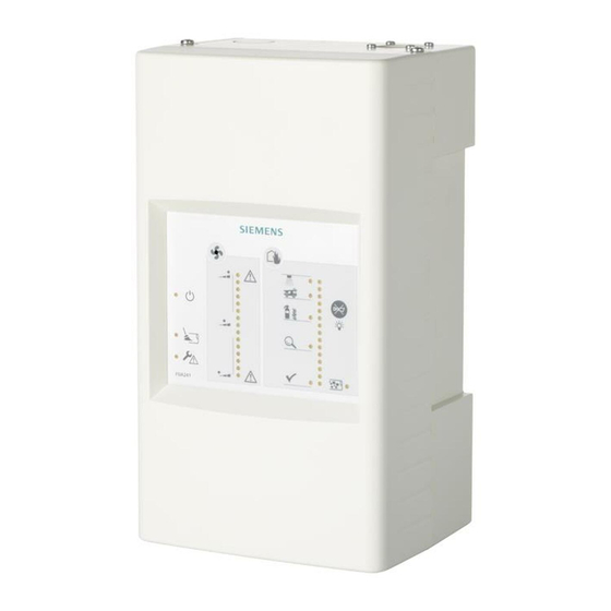
Aspirating smoke detector
Hide thumbs
Also See for FDA241:
- Technical manual (114 pages) ,
- Planning, mounting (56 pages) ,
- Manual (6 pages)

Related Manuals for Siemens FDA241


Summary of Contents for Siemens FDA241
- Page 1 FDA241, FDA221 Aspirating Smoke Detector Mounting Installation Building Technologies A6V10345654_h_en_-- 2015-05-29 Control Products and Systems firealarmresources.com...
- Page 2 Legal notice Legal notice Technical specifications and availability subject to change without notice. © Siemens Switzerland Ltd, 2011 Transmittal, reproduction, dissemination and/or editing of this document as well as utilization of its contents and communication thereof to others without express authorization are prohibited.
-
Page 3: Table Of Contents
'Smoke 4…20 mA' analog output ............... 24 Configurable 'GPI' input ..................26 'Purge' relay output for blowing out (with FDA241 only) ........26 'Dust' relay output for dust value (with FDA241 only) ........27 'Fault' relay output for error messages ............... 27 'Inspect' relay output for early warning (FDA241 only) ........ - Page 4 Building Technologies A6V10345654_h_en_-- Fire Safety 2015-05-29 firealarmresources.com...
-
Page 5: About This Document
You will find more information about the aspirating smoke detectors in document A6V10334410. See the chapter 'Applicable documents [➙ 5]'. Intended use Aspirating smoke detectors FDA241 and FDA221 may only be used for fire detection and fire control purposes. Applicable documents... -
Page 6: Revision History
The table below shows this document's revision history: Modification index Edition date Brief description 2015-05-29 'Connection to the input/output module' chapter added; 'Applicable documents' and ' 'Dust' relay output for dust value (FDA241 only)' chapters amended 2015-02-19 Power supply FP120-Z1 added Battery FA2003-A1 added Editorial changes... -
Page 7: Preparatory Work
Preparatory work Opening and closing the housing cover when the power supply is switched off 2 Preparatory work Opening and closing the housing cover when the power supply is switched off When the housing cover is open, the mini USB connection and the internal indicators are accessible. - Page 8 Preparatory work Opening and closing the housing cover when the power supply is switched off Closing the housing cover The size 2 Phillips screwdriver and the two screws are available. The power supply is switched off. 1. Slide the housing cover in the opposite direction to the arrow (step 2) until it reaches the end position at the bottom.
-
Page 9: Removing And Installing The Housing Cover When The Power Supply Is Switched Off
Preparatory work Removing and installing the housing cover when the power supply is switched off Removing and installing the housing cover when the power supply is switched off NOTICE Electrostatic discharge Damage to electronic components in the aspirating smoke detector ●... - Page 10 Preparatory work Removing and installing the housing cover when the power supply is switched off Removing the housing cover The housing is free from dust. Do not disconnect the connection cable running between the housing cover and the back box. 1.
- Page 11 Preparatory work Removing and installing the housing cover when the power supply is switched off Installing the housing cover Markings on the housing cover and back box The size 2 Phillips screwdriver and the two screws are available. 1. Connect the connection cable plug to the interface card! 2.
-
Page 12: Installation Position And Space Requirements
Preparatory work Installation position and space requirements Installation position and space requirements Installation site requirements Only to be installed within a building where the ambient conditions are permissible No direct sunlight Take into account the additional space required by and the need to access the ... - Page 13 Preparatory work Installation position and space requirements Four connection types are possible: Standard: From above (A) From below (B) when the aspirating smoke detector is installed rotated by 180° From left (D) or right (E) when the aspirating smoke detector is installed ...
- Page 14 Preparatory work Installation position and space requirements Cable entry Position of hole Size of hole Breakthrough on rear 25 x 100 mm Breakthrough on left side of housing Diameter 25 mm Breakthrough on top of housing Diameter 25 mm If the aspirating smoke detector is installed rotated by 180°, the circular breakthroughs are found on the bottom at the right-hand side.
-
Page 15: External Power Unit And Batteries
Suitable power unit: Company Type For battery type Siemens FP120-Z1 G214130 2x FA2003-A1 (12 V, 7 Ah) 2x FA2004-A1 (12 V, 12 Ah) 2x FA2005-A1 (12 V, 17 Ah) You will find more information on the power supply kit FP120-Z1 in document A6V10393194. -
Page 16: Mounting
Mounting Adapting the front indicator to the installation position 3 Mounting Adapting the front indicator to the installation position The aspirating smoke detector can be installed rotated by 180° if required. The front indicator must then also be installed rotated by 180°. 180°... -
Page 17: Fastening On A Level Substructure
Mounting Fastening on a level substructure Fastening on a level substructure A drilling template is punched in the inner packaging of the aspirating smoke detector packaging. The punched symbol in the center of the packaging indicates the airflow direction (air inlet and air outlet). The mounting holes in the back box are not symmetrical, so use the drilling template. -
Page 18: Connecting The Pipe System To The Aspirating Smoke Detector
Mounting Connecting the pipe system to the aspirating smoke detector 4. Screw the four screws into the mounting holes. – Do not screw in the screws as far as the stop. A gap of approx. 10 mm must remain between the screw head and the wall. 5. -
Page 19: Return Line
Mounting Connecting the pipe system to the aspirating smoke detector 3.3.1 Return line If there is an air pressure difference of >45 Pa between the monitored area and the aspirating fire detector, a return line is required. NOTICE Connection between aspirating smoke detector and return line Damage to the return line and/or the aspirating smoke detector ●... -
Page 20: Installing Communication Transponder Fdcc221S
Mounting Installing communication transponder FDCC221S Installing communication transponder FDCC221S Communication transponder FDCC221S may only be installed if the aspirating smoke detector is connected to FDnet/C-NET. Installation is not permitted in the case of standalone operation. Communication transponder FDCC221S has its own ID. The ID of communication transponder FDCC221S is made visible to the detector line and it replaces the ID of the aspirating smoke detector. - Page 21 Mounting Installing communication transponder FDCC221S Mounting The housing cover is open. The aspirating smoke detector's external power supply is switched off and disconnected from the aspirating smoke detector. A communication transponder FDCC221S (accessory) is available. 1. Insert communication transponder FDCC221S into the aspirating smoke detector's interface card with the two spacer bolts as shown in the diagram.
-
Page 22: Installation
Installation Connecting the external power unit 4 Installation CAUTION Electrical voltage on lines Risk of injury due to electric shock ● During mounting and installation work, electrical voltage must not be applied to the lines. Note the positive and negative poles. Only connect one wire per terminal. - Page 23 Installation Connecting the external power unit Procedure A suitable external power unit is available. The aspirating smoke detector's housing cover is removed. 1. Before connecting the external power unit to the terminal block, check the voltage provided by the power unit. Permissible value: DC 24 V ±4 V 2.
-
Page 24: Smoke 4
Smoke value (device default) Dust value (FDA241 only) Airflow (FDA241 only) Fine dust value (FDA241 only) Example illustrating analog input (IN) Connection for DC 9…25 V power supply Smoke value (device default) 4…20 mA analog output... - Page 25 Installation 'Smoke 4…20 mA' analog output Dust value 4…20 mA analog output No dust 4 mA Low dust value 8 mA Medium dust value 12 mA High dust value 16 mA Very high dust value 20 mA Fine dust value 4…20 mA analog output 0 μg/m³...
-
Page 26: Configurable 'Gpi' Input
Monitoring for short circuit and open line (2 resistors) Input for error monitoring on the external power unit 'Purge' relay output for blowing out (with FDA241 only) Relay output for controlling an external blowing-out unit. Connection: n.o. Properties Suitable for controlling an external blowing-out unit. -
Page 27: Dust' Relay Output For Dust Value (With Fda241 Only)
Installation 'Dust' relay output for dust value (with FDA241 only) 'Dust' relay output for dust value (with FDA241 only) Relay output for external monitoring of the dust value. Connection: n.o. Properties Suitable for external monitoring of the dust value. ... -
Page 28: Prealarm' Relay Output For Pre-Alarm
Installation 'PreAlarm' relay output for pre-alarm 'PreAlarm' relay output for pre-alarm Relay output for 'pre-alarm' alarm level. Connection: n.o. (default setting) Properties Activation occurs according to the chosen setting. The connection can be changed to 'n.c.' with the 'FXS2051 ASD Configuration ... -
Page 29: Connecting To The Detector Line With The Fdcc221S
2. Check whether the aspirating smoke detector is being supplied with power. The LED lights up. 3. Start the detector line. The aspirating smoke detector is not detected as FDA241 or FDA221 by the fire control panel. If the aspirating smoke detector has not been detected correctly, refer to the fire control panel documentation for the remainder of the process. -
Page 30: Connection To Input/Output Module
Connection to input/output module 4.12 Connection to input/output module Aspirating smoke detectors FDA241 and FDA221 can be connected to a fire control panel via an input/output module. For fire control panels FC20xx and FC72x, the aspirating smoke detector should be connected via the communication transponder FDCC221S, see chapter 'Connecting to the detector line with the FDCC221S'. - Page 31 Installation Connection to input/output module Variant 1 (for aspirating smoke detector FDA241 only) Input/output module used: FDCIO222 Monitoring: For open line Example representation of monitoring for open line when using an input/output module FDCIO222 1 Fire control panel 4 Monitoring resistor for GPI input...
- Page 32 Installation Connection to input/output module Interface Function 'GPI' Possible to reset an alarm or the status of the aspirating smoke detector using the fire control panel 'Fault' A general fault is indicated on the fire control panel 'Inspect 1' An early warning is indicated on the fire control panel 'Prealarm' A pre-alarm is indicated on the fire control panel 'Fire 1'...
- Page 33 Installation Connection to input/output module Variant 2 (for aspirating smoke detectors FDA241 or FDA221) Input/output module used: FDCIO222 Monitoring: For open line and short-circuit Example representation of monitoring for open line and short-circuit when using an input/output module FDCIO222 1 Fire control panel...
- Page 34 Installation Connection to input/output module Interface Function 'GPI' Possible to reset an alarm or the status of the aspirating smoke detector using the fire control panel 'Fault' A general fault is indicated on the fire control panel 'Prealarm' A pre-alarm is indicated on the fire control panel 'Fire 1' An alarm is indicated on the fire control panel 'Fire 2'...
-
Page 35: Index
Index Index Batteries Capacitance, 15 Operation on detector line, 15 Standalone operation, 15 Battery Suitable power unit, 15 Charging current, 15 Drilling template, 17 External power unit Connection, 22 Requirements, 15 Several aspirating smoke detectors, 22 Front indicator Adapting the installation position, 16 Housing cover Closing when the power supply is switched off, 8 Installing, 11... - Page 36 Issued by © Siemens Switzerland Ltd, 2011 Siemens Switzerland Ltd Technical specifications and availability subject to change without notice. Building Technologies Division International Headquarters Gubelstrasse 22 CH-6301 Zug Tel. +41 41-724 24 24 www.siemens.com/buildingtechnologies Document ID A6V10345654_h_en_-- Handbook FD20/FD720 Edition...