Table of Contents
Advertisement
Margin
Titelseite OHNE Beschnitt in RGB
blue dark 100 % Stone gray 100%
Edition
08/2018
1/20x
Siemens Sans, Bold
11/9/7,5 pt, white
Absatzformat: 05 Ausgabe
Alle Schriften sind als Absatzformat hinterlegt!!!
wenn möglich in gleicher Schriftgruppe bleiben!
System
Produktgruppe
Titel
Dokuklasse
URL
Ausgabe
1/10x
Manual
1/14x
1/10x
SENTRON
Measuring Devices
Multimeter 7KT PAC1600
1/5x
1/28x
1/20x
1/20x
1/10x
Bufferzone
groß
mittel
klein
36
30
26
18
16
14
13
12
11
13
12
11
9
9
9
11
9
7,5
1 x
Siemens Sans, Bold,
11/12/13 pt, white
Absatzformat: 04 Dokuklasse
Siemens Sans, Bold,
9 pt, black
Absatzformat: 06 URL
2 x
Wird mehr Text verwendet
Verlaufsfeld nach oben
erweitern. Abstände von
Rand zu Text einhalten!
Siemens Sans, Roman,
36/30/26 pt, white
Siemens Sans, Bold
Absatzformat: 01 System
18/16/14 pt, white
Absatzformat: 02 Produkt
Siemens Sans, Roman,
13/12/11 pt, white
Absatzformat: 03 Titel
siemens.de/powermonitoring
Margin
1/5x
1/10x
1/5x
1/28x
1/20x
1/20x
Advertisement
Table of Contents

Related Manuals for Siemens SENTRON 7KT1681

Summary of Contents for Siemens SENTRON 7KT1681
- Page 1 System Produktgruppe Titel Dokuklasse Ausgabe Wird mehr Text verwendet Verlaufsfeld nach oben erweitern. Abstände von Rand zu Text einhalten! 1/10x Siemens Sans, Bold, 11/12/13 pt, white Manual Absatzformat: 04 Dokuklasse 1/14x 1/5x 1/10x 1/10x SENTRON Siemens Sans, Roman, 36/30/26 pt, white...
- Page 3 ___________________ Introduction ___________________ Safety instructions ___________________ SENTRON Description ___________________ Installation/removal Measuring devices 7KT multimeter ___________________ Connecting ___________________ Commissioning Manual ___________________ Service and maintenance ___________________ Technical data ___________________ Dimensional drawings ___________________ ESD guidelines 08/2018 2514284149-01...
- Page 4 Note the following: WARNING Siemens products may only be used for the applications described in the catalog and in the relevant technical documentation. If products and components from other manufacturers are used, these must be recommended or approved by Siemens. Proper transport, storage, installation, assembly, commissioning, operation and maintenance are required to ensure that the products operate safely and without any problems.
-
Page 5: Table Of Contents
Table of contents Introduction ..............................5 Components of the product ...................... 5 Latest information ........................5 Advanced training courses ....................... 5 Open Source Software ......................6 Qualified personnel ........................7 Safety instructions ............................. 9 Safety instructions ........................9 Security information ........................ 11 Description ............................... - Page 6 Table of contents Connecting .............................. 41 Connection examples ......................42 Connecting the device ......................47 Commissioning ............................49 Overview ..........................49 Applying the measuring voltage ..................... 50 Parameterizing with powerconfig ................... 50 Modbus address register for devices with Modbus interface ..........52 6.4.1 Modbus measured variables with the function codes 03 and 04 ...........
-
Page 7: Introduction
Introduction Components of the product The package includes: ● Operating instructions ● 7KT PAC1600 multimeter Available accessories ● Software powerconfig (https://support.industry.siemens.com/cs/ww/en/view/63452759) ● Software powermanager (https://support.industry.siemens.com/cs/ww/en/view/109746290) Latest information Up-to-the-minute information You can find further support on the Internet at: (http://www.siemens.com/lowvoltage/technical-assistance) Advanced training courses Find out about training courses on offer on the following link. -
Page 8: Open Source Software
Product or any OSS components contained in it if they are modified or used in any manner not specified by SIEMENS. The license conditions listed below may contain disclaimers that apply between you and the respective licensor. -
Page 9: Qualified Personnel
Introduction 1.5 Qualified personnel Qualified personnel Some of the following tasks are carried out when hazardous voltage is present. For this reason, they must only be carried out by qualified personnel who are familiar with the safety regulations and precautions and who follow the safety regulations and precautions. ●... -
Page 11: Safety Instructions
Safety instructions Safety instructions DANGER Risk of death due to electric shock and arc flashover! For the 5 A device, it is only possible to measure the current via external current transformers. When using the current transformers, the circuit is not protected by a fuse. •... - Page 12 Safety instructions 2.1 Safety instructions NOTICE Device damage due to condensation Humidity may cause condensation on the device if temperature balance has not been reached. Condensation may damage the device when it is connected to the power supply. Do not connect the device to the power supply until temperature balance has been reached.
-
Page 13: Security Information
In order to protect plants, systems, machines and networks against cyber threats, it is necessary to implement – and continuously maintain – a holistic, state-of-the-art industrial security concept. Siemens’ products and solutions only form one element of such a concept. Customers are responsible for preventing unauthorized access to their plants, systems, machines and networks. -
Page 15: Description
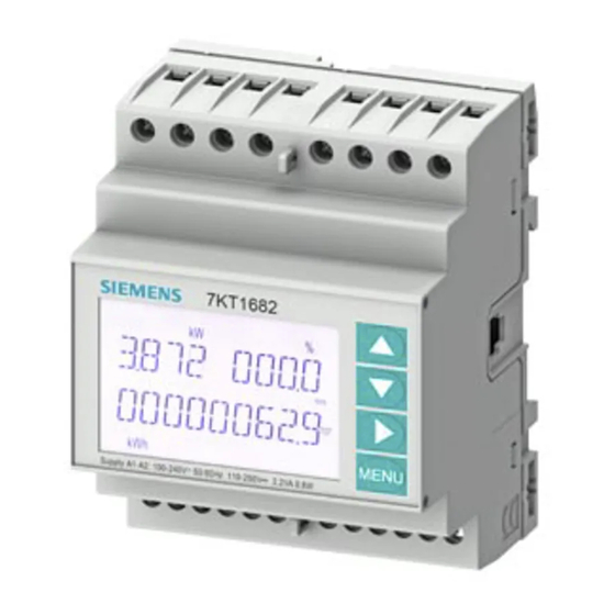
Description Performance features The 7KT1681 and 7KT1682 multimeters are designed such that they combine maximum operating comfort with a wide range of advanced functions, and this despite the extremely restricted dimensions of the modular enclosure (only 4U). The backlit LCD offers intuitive operation of the clearly laid out user interface. The 7KT1682 additionally features an insulated RS 485 communications interface with Modbus protocol support. -
Page 16: Measuring Inputs
Description 3.2 Measuring inputs Measuring inputs 3.2.1 Current measurement NOTICE Device damage due to DC current The device is not suitable for measuring DC current. Only measure AC current with the device. Design of the device The devices are designed for a rated current of 1 A or 5 A for connecting standard current transformers. -
Page 17: 7Kt Pac1600 Multimeter
Description 3.3 7KT PAC1600 multimeter Measuring input voltages The device is designed for the following measuring input voltages: ● For measuring input voltages up to 415 V phase-to-neutral ● For measuring input voltages up to 720 V phase-to-phase 7KT PAC1600 multimeter ①... -
Page 18: Keypad Functions
Description 3.3 7KT PAC1600 multimeter ● Wide-range auxiliary power supply unit (100 V AC … 240 V AC) ● Two-level password protection for settings ● Backup copy of original settings ● Texts available in six languages Display indications ① Measured variable display ②... -
Page 19: Selection Of Measured Values
Description 3.3 7KT PAC1600 multimeter Access the main menu 1. Press the Menu key. The main menu is displayed with the available options: – SET: Access the setup menu – CMD: Access the command menu – PAS: Password entry The selected option flashes. The text for the selection scrolls in the alphanumeric display. -
Page 20: Display
Description 3.3 7KT PAC1600 multimeter key permits access to subpages on every page (e.g. to display the maximum and minimum values for the selected measurement). The currently displayed subpage is displayed on the bottom right by one of the following symbols: ●... - Page 21 Description 3.3 7KT PAC1600 multimeter Pages Subpages Active energy, active power – Active energy meter import • kWh+(SYS) PAR TAR-1 • kWh+(SYS) TOT TAR-2 • Active energy meter export • kWh-(SYS) PAR TAR-1 • kWh-(SYS) TOT TAR-2 • Reactive energy meter import •...
- Page 22 Description 3.3 7KT PAC1600 multimeter Pages Subpages Energy meter (L2) • kvarh+(L2) PAR TAR-1 • kvarh+(L2) TOT TAR-2 • Energy meter (L3) • kvarh+(L3) PAR TAR-1 • kvarh+(L3) TOT TAR-2 • Energy meter (L1) • kvarh-(L1) PAR TAR-1 • kvarh-(L1) TOT TAR-2 •...
- Page 23 Description 3.3 7KT PAC1600 multimeter Pages Subpages Reactive power • Q(L1), Q(L2), Q(L3), Q(TOT) • • • Apparent power • S(L1), S(L2), S(L3), S(TOT) • • • Power factor • PF(L1), PF(L2), PF(L3), PF(demand) • • Active power unbalance • L1-L2, L2-L3, L3-L1 •...
-
Page 24: Harmonic Displays
Description 3.3 7KT PAC1600 multimeter Pages Subpages Hour counter • hhhhhh-mm-ss PAR-1 • PAR-2 • PAR-3 • PAR-4 • Limit threshold – LIM1–LIM2–LIM3–LIM4 Alarms – ALA1–ALA2–ALA3–ALA4 Tariff selection – (tAr-1 and tAr-2) Device information – MODEL, REV SW, SER. No. 3.3.4 Harmonic displays The 7KT1681 and the 7KT1682 provide phase analysis up to the 15th harmonic for the... -
Page 25: Parameterization
Description 3.4 Parameterization Parameterization 3.4.1 Parameter setting (setup) from the front panel 1. Press the Menu key in the standard measurement display to call the main menu. 2. Select SET and press to call the Settings menu. The display shows the first menu level P01 on the top left with selection 01 flashing. 3. - Page 26 Description 3.4 Parameterization 5. Select the submenu and the serial parameter number as appropriate. Use the keys as follows: – : Back – : Decrease – : Increase – : Next 6. After setting the required parameter number, use the key to switch to edit mode.
-
Page 27: Energy Measurements
Description 3.4 Parameterization Note The devices allow you to create a backup copy of the data which can be edited using the keys in EEPROM. You can write this data back into RAM if required. You can find more information on backing up and restoring this data in chapter Command menu (Page 36). -
Page 28: Hour Counter
Description 3.4 Parameterization Exported active energy If the display of energy for the individual phases is activated (P02.10 = ON), the display shows three independent additional pages (1 page per phase), including total and partial energy. 3.4.3 Hour counter When the hour counter is activated, the multimeter displays the hour counter page in the following format: ①... -
Page 29: Limit Threshold Status Display
Description 3.4 Parameterization 3.4.4 Limit threshold status display If limit thresholds are activated, the device displays the page with the corresponding status and the following format: ① Limit thresholds deactivated ④ Limit thresholds activated ● If the limit threshold is activated, ON flashes. ●... -
Page 30: Alarm Display
Description 3.4 Parameterization 3.4.5 Alarm display If alarms are activated, the multimeter displays the page with the corresponding status and the following format: ① Alarm deactivated ② Alarm text activated ③ Alarm code activated ④ Alarm activated ● If the alarm is activated, ON flashes with the triangle symbol. ●... - Page 31 Description 3.4 Parameterization The description of the parameters visible on the display can deviate from the details in the table in some cases due to the restricted number of available characters. The parameter code is the most reliable means of reference. M01 General Unit Default...
- Page 32 Description 3.4 Parameterization M02 Utility Unit Default Range P02.01 Language – English English • Italiano • Francais • Espanol • Portuguese • Deutsch • P02.02 High backlight level 0 … 100 P02.03 Low backlight level 0 … 50 P02.04 Low backlight delay 5 …...
- Page 33 Description 3.4 Parameterization P02.10 Permits the measurement and display of energies according to individual phases. P02.11 Permits the measurement and display of voltage and current unbalances. P02.12 Activates the measurement and display of voltage and current THDs (% har- monic distortion) and display of the harmonics for current and voltage (2 ... 15). P02.13 Permits the calculation and display of phase shift.
- Page 34 Description 3.4 Parameterization M04 Integration Unit Default Range P04.01 Demand values – Shift Fixed • Shift • Bus (7KT1682) • P04.02 Power demand values 1 … 60 P04.03 Current demand values P04.04 Voltage demand values P04.05 Frequency demand values P04.01 Selection of calculation mode •...
- Page 35 Description 3.4 Parameterization P05.01 OFF (hour counter deactivated): The device does not display the page for hour counter measurement. P05.02 • OFF: The partial hour counter is not incremented. • ON: Partial hour counter is incremented when the device is measuring energy.
- Page 36 Description 3.4 Parameterization M08 Limit thresholds (LIMn, n = 1 to 4) Note This menu is divided into 4 sections for limit thresholds LIM 1 ... 4. Unit Default Range P08.n.01 Reference measure – OFF … (measures) P08.n.02 Function • •...
- Page 37 Description 3.4 Parameterization M09 Alarms (ALAn, n = 1 … 4) Note This menu is divided into 4 sections for alarms ALA1 ... 4. Default Range P09.n.01 Alarm source • LIMx • P09.n.02 Channel number (n) 1 … 4 P09.n.03 Reset mode •...
-
Page 38: Command Menu
Description 3.4 Parameterization 3.4.7 Command menu The command menu allows you to perform occasional operations (e.g. to reset measured variables and counters). After entering the password for the extended level, you can also use the command menu to perform automatic operations which are useful for the configuration of the device. The following functions are available in the command menu, separated according to the required access level. -
Page 39: Wiring Test
Description 3.5 Wiring test Wiring test The wiring test checks whether the multimeter has been installed correctly. Requirements In order to run the wiring test, the multimeter must be connected to an active system and the following conditions must be fulfilled: ●... -
Page 40: Powerconfig
Description 3.6 Supporting software ● Demand curve ● Reporting, different report types (e.g. cost center report) ● Load monitoring of reaction plans ● Power peak analysis (available as of powermanager V3.0 SP1) ● Support of distributed plants (systems) ● Archiving system ●... -
Page 41: Installation/Removal
Installation/removal Installation location WARNING Possible risk of death due to damaged device! Using devices when they are damaged may result in death, serious injury, or property damage. • Do not install damaged devices. • Never start up damaged devices. NOTICE Device damage due to condensation! Sudden fluctuations in temperature can lead to condensation. -
Page 42: Removal
Installation/removal 4.3 Removal Removal 7KT multimeter Manual, 08/2018, 2514284149-01... -
Page 43: Connecting
Connecting Safety instructions DANGER Risk of death due to hazardous voltage! Before starting work, disconnect the system and the device from the power supply. DANGER Risk of death due to electric shock and arc flashover! For the 5 A device, it is only possible to measure the current via external current transformers. -
Page 44: Connection Examples
Connecting 5.1 Connection examples Note RS 485 termination recommended In order to avoid reflection on the bus cable, we recommend fitting a 120 Ω terminating resistor at the beginning and end of the bus cable. To establish Modbus RTU communication, the communication parameters must be known. These include baud rate and format. - Page 45 Connecting 5.1 Connection examples Three-phase connection with or without neutral conductor P01.07 = L1-L2-L3-N or L1-L2-L3 Two-phase connection P01.07 = L1-N-L2 7KT multimeter Manual, 08/2018, 2514284149-01...
- Page 46 Connecting 5.1 Connection examples Single-phase connection P01.07 = L1-N Three-phase connection of the same load with or without neutral conductor P01.07 = L1-L2-L3-N-BIL or L1-L2-L3-BIL 7KT multimeter Manual, 08/2018, 2514284149-01...
- Page 47 Connecting 5.1 Connection examples Three-phase connection without neutral conductor (ARON circuit, current transformer in L1 and L2) P01.07 = L1-L2-L3 Three-phase connection without neutral conductor (ARON circuit, current transformer in L1 and L3) P01.07 = L1-L2-L3 7KT multimeter Manual, 08/2018, 2514284149-01...
- Page 48 Connecting 5.1 Connection examples Three-phase connection with neutral conductor via voltage transformer P01.07 = L1-L2-L3-N Three-phase connection without neutral conductor via voltage transformer Set P01.04, P01.05 and P01.06 P01.07 = L1-L2-L3 7KT multimeter Manual, 08/2018, 2514284149-01...
-
Page 49: Connecting The Device
Connecting 5.2 Connecting the device Connecting the device NOTICE Irreparable damage to the device The wrong system connection can cause irreparable damage to the device. Before connecting the device, ensure that the local power supply conditions match the specifications on the type plate. Procedure 7KT multimeter Manual, 08/2018, 2514284149-01... - Page 50 Connecting 5.2 Connecting the device Circuit diagram Figure 5-1 * Only necessary with phase L Parameterization You can find information on parameterization in the chapter Parameter setting (setup) from the front panel (Page 23). 7KT multimeter Manual, 08/2018, 2514284149-01...
-
Page 51: Commissioning
Commissioning Overview Prerequisites ● The device has been installed. ● The device has been connected in accordance with the possible connection methods. Steps for starting up the device NOTICE Risk of malfunction or device failure! Incorrect connection can result in malfunctions and failure of the device. •... -
Page 52: Applying The Measuring Voltage
Parameterizing with powerconfig You can download the powerconfig configuration software from the Industry Online Support website via the link (https://support.industry.siemens.com/cs/ww/en/view/63452759). Information on how to use powerconfig can be found in the Online Help of the configuration software or by contacting Technical Support. - Page 53 Commissioning 6.3 Parameterizing with powerconfig 6. Enter the communication parameters: – COM port – Address – Baud rate – Format – Protocol 7. Click the Start search button. The "Result" window displays all the devices found. 8. Select the required device. 9.
-
Page 54: Modbus Address Register For Devices With Modbus Interface
Commissioning 6.4 Modbus address register for devices with Modbus interface Modbus address register for devices with Modbus interface 6.4.1 Modbus measured variables with the function codes 03 and 04 Address Number of Measured variable Unit Format registers 0002H L1 phase voltage V/100 Unsigned long 0004H... - Page 55 Commissioning 6.4 Modbus address register for devices with Modbus interface Address Number of Measured variable Unit Format registers 0058H L3 voltage THD 005AH L1 current THD 005CH L2 current THD 005EH L3 current THD 0060H L1-2 voltage THD 0062H L2-3 voltage THD 0064H L3-1 voltage THD 0070H...
- Page 56 Commissioning 6.4 Modbus address register for devices with Modbus interface Address Number of Measured variable Unit Format registers 0C00H 2nd harmonic, L1 voltage Unsigned long 0C02H 3rd harmonic, L1 voltage … 0C1AH 15th harmonic, L1 voltage 0C40H 2nd harmonic, L2 voltage …...
- Page 57 Commissioning 6.4 Modbus address register for devices with Modbus interface Address Number of Measured variable Unit Format registers 1B20H Total active energy import kWh/100 Unsigned long-long 1B24H Total active energy export 1B28H Total reactive energy import kvarh/100 1B2CH Total reactive energy export 1B30H Total apparent energy kVAh/100...
-
Page 58: Modbus Command Parameters
Commissioning 6.4 Modbus address register for devices with Modbus interface 6.4.2 Modbus command parameters Modbus function code 06 Address WORDS Measured variables UNIT FORMAT 2FF0H Reset HI-LO values Unsigned int 2FF0H Reset max. average values Unsigned int 2FF0H Reset partial energy Unsigned int 2FF0H Reset partial hour counter... -
Page 59: Setup Parameters
Commissioning 6.4 Modbus address register for devices with Modbus interface Measured variable Current transformer 2 on phase L3 Current transformer 3 on phase L1 Current transformer 3 on phase L2 6.4.3 Setup parameters Note You can find further details, such as default values and units, in chapter Parameter tables (Page 28). - Page 60 Commissioning 6.4 Modbus address register for devices with Modbus interface M03 Password CODE MENU WORDS ADDRESS P03.01 Enable password 5100H P03.02 User-level password 9999 1000 5102H P03.03 Administrator password 9999 2000 5104H M04 Integration CODE MENU WORDS ADDRESS P04.01 Demand values 5180H P04.02 Power demand values...
- Page 61 Commissioning 6.4 Modbus address register for devices with Modbus interface Rules for reading and writing Parameters are read and written in accordance with the following rules: Address Words Description Function Example 0x5000 Selection of menu number 4 read – 6 write Write the value 1 to select menu number 1.
-
Page 63: Service And Maintenance
Service and maintenance The device has been calibrated by the manufacturer before shipping. Recalibration is not required provided the environmental conditions are maintained. Firmware update A firmware update is not possible. Fault elimination measures Fault Measures Device is not working. Check power supply connection. -
Page 64: Warranty
Warranty Note Loss of warranty If you open the device, you will invalidate the Siemens warranty. Only the manufacturer is permitted to carry out repairs to the devices. Return faulty or damaged devices to Siemens for repair or replacement. Procedure If the device is faulty or damaged, proceed as follows (only during the warranty period): 1. -
Page 65: Technical Data
Technical data Technical data 7KT PAC1600 multimeter Auxiliary power Nominal voltage 100 V~ … 240 V~ • 110 V= … 250 V= • Operating voltage range 90 V~ … 264 V~ • 93.5 V= … 300 V= • Nominal frequency 45 Hz …... - Page 66 Technical data 8.1 Technical data Measuring accuracy Reference conditions Temperature +23 °C ±2 °C Phase-to-neutral voltage ±0.5% (50 V~ … 480 V~) ±0.5 digit Phase-to-phase voltage ±0.5% (80 V~ … 830 V~) ±0.5 digit Current (xx/5) ±0.5% (0.1 in … 1.2 in) ±0.5 digit Active energy Class 1 (IEC/EN 62053-21) Reactive energy...
- Page 67 Technical data 8.1 Technical data Certifications The 7KT PAC1600 multimeter complies with the requirements of the following European Directives: ● DIRECTIVE 2014/30/EU OF THE EUROPEAN PARLIAMENT AND COUNCIL of February 26, 2014, on the harmonization of the laws of the Member States relating to electromagnetic compatibility and repealing the Directive 89/336/EEC ●...
-
Page 68: Labels On The Enclosure
Technical data 8.2 Labels on the enclosure Labels on the enclosure Symbol, label Explanation PAC1600 Product/device designation LQN/YYMMDDxxxxxx Serial number of the device EAC certification Overvoltage category CAT III for current and voltage inputs Protective insulation, device with safety class II CE mark. -
Page 69: Dimensional Drawings
Dimensional drawings 7KT multimeter Manual, 08/2018, 2514284149-01... -
Page 71: Esd Guidelines
ESD guidelines Electrostatic sensitive devices (ESD) Electrostatic sensitive devices are destroyed by voltage and energy levels far below the limits of human perception. Voltages of this kind occur as soon as a device or an assembly is touched by a person who is not electrostatically discharged. Electrostatic sensitive devices which have been subject to such voltages are usually not immediately recognized as being defective, because a malfunction does not occur until after an extended period of operation. - Page 72 ESD guidelines A.1 Electrostatic sensitive devices (ESD) ESD workstation The diagrams below illustrate the required ESD protective measures for electrostatic sensitive devices. ① ESD seat ② ESD standing position ③ ESD seat and ESD standing position Protective measures Conductive floor ESD table ESD footwear ESD smock...
-
Page 73: Index
Index Access the main menu, 17 Latest information, 5 Accessories, 5 Arrow keys, 16 Menu key, 16 Modbus command parameters CE conformity, 65 Modbus function code 06, 56 Circuit diagram, 48 Wiring test results, 56 Single-phase connection, 44 Three-phase connection of the same load with or without neutral conductor, 44 Three-phase connection with neutral conductor via Open Source Software, 6... - Page 74 Index Memory, 13 Wiring test Optional interfaces depending on device version, 13 Requirements, 37 powerconfig Run, 37 Functions, 38 powermanager Functions, 37 Qualified personnel, 7, 42 Safety instructions, 9 Safety-related symbols, 10 Selecting measured values Programming functions, 18 Set password, 17 Technical data Accuracy, 63 Additional faults, 64...