
Related Manuals for Siemens 7MF1570


Summary of Contents for Siemens 7MF1570
- Page 1 Siemens USER'S MANUAL Energy & Automation UMMPS-1 Rev. 2 January 2003 Supersedes Rev. 1 Pressure Transmitter for Level Measurement Model 7MF1570...
-
Page 3: Table Of Contents
UMMPS-1 Contents Table of Contents Title Page Introduction ...................................1 Operation ..................................2 Installation ..................................3 Wiring....................................4 Calibration ..................................4 Maintenance ..................................5 Model Designation ................................5 Specifications ................................6 Junction Box..................................7 Cable Hanger .................................8 Product Support ................................8 Warranty ..................................10 January 2003... - Page 4 Contents UMMPS-1 January 2003...
-
Page 5: Introduction
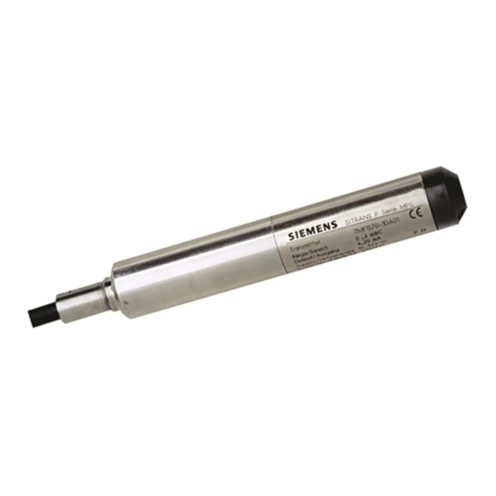
Installation and Maintenance Introduction The Siemens Model 7MF1570 pressure transmitter is used for hydrostatic liquid level measurement. Typical applications include wastewater treatment and water supply, and many other applications in a variety of industries. The transmitter measures hydrostatic pressure using the formula: p = ρ... -
Page 6: Operation
An optional junction box provides screw terminals for cable termination and for connecting to a receiving instrument, such as a Siemens Model 353 Process Automation Controller. The cable shield is connected to the housing and is connected by the user to earth ground. Within the junction box, the vent pipe is exposed to atmospheric pressure. -
Page 7: Installation
UMMPS-1 Installation and Maintenance Installation The transmitter is installed suspended on the cable. The cable is routed through a cable hanger and into the junction box as shown in figure 1. Figure 3 shows transmitter dimensions. 27 mm 1.06 in. Protective Cap Cable Sheath + Brown... -
Page 8: Wiring
Installation and Maintenance UMMPS-1 Wiring WARNING Electrical shock hazard Hazardous voltage can cause death or serious injury. Remove power from all wires and terminals before working on this equipment. 1. Remove power from all wires and terminals to eliminate any electrical shock hazard. 2. -
Page 9: Maintenance
If ordering, select the desired measuring range, read across the table to the Range Character (*) and insert that character into the model number at the head of the column. Example: 7MF1570-1MA01 SITRANS P Pressure Transmitter, MPS Series (Submersible Sensor),... -
Page 10: Specifications
Installation and Maintenance UMMPS-1 Specifications Input Measured variable Pressure Measuring range Overload limit 0-6 ft WC 47 ft WC 0-12 ft WC 47 ft WC 0-20 ft WC 100 ft WC 0-30 ft WC 100 ft WC 0-60 ft WC 200 ft WC Output Output signal... -
Page 11: Junction Box
- 10V) / 0.02A in Ohms Junction Box The optional junction box (PN 7MF1570-8AA) is shown below. It serves as the electromechanical interface between the transmitter cable and the cables to receiving instrument and the user-supplied power supply. It contains a terminal block for wire connections and cable clamping connectors. -
Page 12: Cable Hanger
Technical Information Center (TIC). Each region has a customer service center that provides direct telephone support on technical issues related to the functionality, application, and integration of products supplied by Siemens Energy & Automation, Process Industries Division. Regional contact information is provided in Table 1-2. - Page 13 Installation and Maintenance TABLE 1-2 Contact Information Telephone +1 215 646 7400, extension 4993 +1 215 283 6358 E-mail MandCTechSupp@sea.siemens.com NORTH AMERICA Hours of Operation 8 a.m. to 6 p.m. eastern time Monday – Friday (except holidays) Public Internet Site www.sea.siemens.com/ia/...
-
Page 14: Warranty
1201 Sumneytown Pike P.O. Box 900 Spring House, PA 19477-0900 USA Warranty will be null and void if repair is attempted without authorization by a member of the Service Department or Product Support Group, Siemens Energy & Automation, Inc. January 2003...