Table of Contents
Advertisement
Available languages
Available languages
Quick Links
S S S S I I I I T T T T R R R R A A A A N N N N S S S S P P P P
T T T T r r r r a a a a n n n n s s s s m m m m i i i i t t t t t t t t e e e e r r r r f f f f o o o o r r r r p p p p r r r r e e e e s s s s s s s s u u u u r r r r e e e e , , , , M M M M K K K K I I I I I I I I s s s s e e e e r r r r i i i i e e e e s s s s
I I I I n n n n s s s s t t t t r r r r u u u u c c c c t t t t i i i i o o o o n n n n M M M M a a a a n n n n u u u u a a a a l l l l
M M M M e e e e s s s s s s s s u u u u m m m m f f f f o o o o r r r r m m m m e e e e r r r r f f f f ü ü ü ü r r r r D D D D r r r r u u u u c c c c k k k k , , , , S S S S e e e e r r r r i i i i e e e e M M M M K K K K I I I I I I I I
7 7 7 7 M M M M F F F F 4 4 4 4 0 0 0 0 1 1 1 1 0 0 0 0
E E E E d d d d i i i i t t t t i i i i o o o o n n n n 0 0 0 0 3 3 3 3 / / / / 0 0 0 0 1 1 1 1
Advertisement
Chapters
Table of Contents

Related Manuals for Siemens SITRANS P MK II Series


Summary of Contents for Siemens SITRANS P MK II Series
- Page 1 S S S S I I I I T T T T R R R R A A A A N N N N S S S S P P P P T T T T r r r r a a a a n n n n s s s s m m m m i i i i t t t t t t t t e e e e r r r r f f f f o o o o r r r r p p p p r r r r e e e e s s s s s s s s u u u u r r r r e e e e , , , , M M M M K K K K I I I I I I I I s s s s e e e e r r r r i i i i e e e e s s s s I I I I n n n n s s s s t t t t r r r r u u u u c c c c t t t t i i i i o o o o n n n n M M M M a a a a n n n n u u u u a a a a l l l l E E E E d d d d i i i i t t t t i i i i o o o o n n n n 0 0 0 0 3 3 3 3 / / / / 0 0 0 0 1 1 1 1 M M M M e e e e s s s s s s s s u u u u m m m m f f f f o o o o r r r r m m m m e e e e r r r r f f f f ü...
- Page 2 SIMATICr, SIPARTr, SIPROMr, SIRECr, SITRANSr sind eingetragene Marken der Siemens AG. Die übrigen Bezeichnungen in diesem Handbuch können Marken sein, deren Benutzung durch Dritte für deren Zwecke die Rechte der Inhaber verletzen können. SIMATICr, SIPARTr, SIPROMr, SIRECr, SITRANSr are registered trademarks of Siemens AG.
- Page 3 DELLSONICS 北京迪妙声科技有限公司 BEJING DELLSONICS SCIENCE & TECHNOLOGY LTD. 公 司 简 介 北京迪妙声科技有限公司(原名北京妙声力科技有限公司) ,位于北京市海淀区中关村 南大街,是与西门子公司德国总部正式签约的西门子过程仪表及分析仪器核心合作伙伴, 也是西门子北方区域规模最大、实力最强的优秀代理商。 公司主营: 一、 西门子-妙声力(Milltronics)系列物位产品:超声波物位计、超声波液位差计、超声波泥水界 面计、超声波明渠流量计、雷达物位计、射频导纳物位计、射频导纳油水界面计、 ;射频导纳物位开关、 音叉式物位开关、阻旋式物位开关;皮带称、固体质量流量计、冲板流量计等。 二、 西门子过程仪表产品:电磁流量计、质量流量计、超声波流量计、 温度变送器、压力变送器、 阀门定位器、气体分析仪等。 三、 德国 UWT 公司的阻旋式料位开关、音叉式料位开关、重锤式料位计等产品。 四、 自行研发生产超声波液位计、温度变送器、压力变送器、数显表及油田专用仪器等产品。 成立于 1954 年的西门子-妙声力公司 是世界公认的超声波物位测量领域 (Milltronics) 的领导者, 全球最大的超声波物位仪表生产厂家, 在超声波、 雷达、 电容技术领域拥有超过 60 项专利,超声波产品的综合性能指标经美国《控制》杂志评比,其综合性能名列全球第一!...
-
Page 4: Table Of Contents
Betriebsanleitung 7MF4010 Inhaltsverzeichnis Technische Beschreibung ......Anwendungsbereich ........Arbeitsweise . - Page 5 7MF4010 Betriebsanleitung Sicherheitstechnische Hinweise GEFAHR bedeutet, dass Tod, schwere Körperverletzung oder erheblicher Sachscha- den eintreten werden, wenn die entsprechenden Vorsichtsmaßnahmen nicht getroffen werden. WARNUNG bedeutet, dass Tod oder schwere Körperverletzung eintreten können, wenn die entsprechenden Vorsichtsmaßnahmen nicht getroffen werden. VORSICHT mit Warndreieck bedeutet, dass eine leichte Körperverletzung eintreten kann, wenn die entsprechenden Vorsichtsmaßnahmen nicht getroffen werden.
- Page 6 Vereinbarung, Zusage oder eines Rechtverhält- nisses ist oder diese abändern soll. Sämtliche Verpflichtungen der Siemens AG ergeben sich aus dem jeweiligen Kaufvertrag, der auch die voll- ständige und allein gültige Gewährleistungsregelung enthält. Diese vertragli- chen Gewährleistungsbestimmungen werden durch die Ausführungen der Anleitung weder erweitert noch beschränkt.
- Page 7 7MF4010 Betriebsanleitung Qualifiziertes Personal sind Personen, die mit Aufstellung, Montage, Inbetriebsetzung und Betrieb des Produktes vertraut sind und über die ihrer Tätigkeit entsprechenden Qualifikatio- nen verfügen, wie z. B.: · Ausbildung oder Unterweisung bzw. Berechtigung, Geräte/Systeme gemäß des Standards der Sicherheitstechnik für elektrische Stromkreise, hohe Drücke und aggressive sowie gefährliche Medien zu betreiben und zu warten.
-
Page 8: Technische Beschreibung
Betriebsanleitung 7MF4010 Technische Beschreibung Anwendungsbereich Der Messumformer SITRANS P mißt den Druck nichtaggressiver und aggressiver Gase, Dämpfe und Flüssigkeiten. Möglich sind Messspannen zwischen 0,23 und 160 bar. Das Ausgangssignal ist ein eingeprägter Gleichstrom von 4 bis 20 mA, der dem Eingangsdruck linear proportional ist. - Page 9 7MF4010 Betriebsanleitung Testbuchsen, Analoganzeiger (wahlweise) Messver- 4 bis 20 mA stärker Stromtreiber 4...20mA Silizium-Drucksensor Füllflüssigkeit Trennmembran Prozessabschluss Ausgangsstrom Hilfsenergie Eingangsgröße Druck Bild 1 Messumformer SITRANS P für Druck, Funktionsplan SITRANS P , MK II C73000-B5674-C100-02...
-
Page 10: Technische Daten
Betriebsanleitung 7MF4010 Technische Daten Funktionsdaten Messspannen und Überlastgrenzen Messspanne Überlastgrenzen stufenlos einstellbar stufenlos einstellbar untere obere 0,23 bis 1 bar -1 bar 6 bar ≙ 0,89 bis 4 bar -1 bar 10 bar ≙ 3,55 bis 16 bar 0,355 bis 1,6 MPa -1 bar 32 bar... - Page 11 7MF4010 Betriebsanleitung Übertragungsverhalten bei steigender Kennlinie, Messanfang 0 bar. Alle Angaben beziehen sich auf die Ausgangsspanne. Messabweichung bei Grenzpunkteinstellung ≤0,25 % (einschließlich Hysterese und Reproduzierbarkeit) Zeitkonstante T ca. 0,3 s Langzeitdrift ≤0,2 % je 12 Monate bei max. Mess- spanne Einfluss der Umgebungstemperatur --10 _C bis 60 _C ≤...
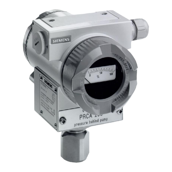
- Page 12 Betriebsanleitung 7MF4010 Werkstoffe der messstoffberührten Teile Anschlusszapfen Edelstahl, Werkstoff-Nr. 1.4404 Trennmembran Edelstahl, Werkstoff-Nr. 1.4404 Messzellenfüllung Silikonöl Elektronikgehäuse Kupferarmer Aluminiumdruckguss GD-AlSi 12, Lack auf Polyesterbasis, Typenschild aus Edelstahl Montagewinkel (Option) Stahl, verzinkt und gelbchromatiert oder Edelstahl Analoganzeiger (Option) Lineare Skale 0 bis 100 % oder kunden- spezifische Skale Gewicht Etwa 1,5 kg (ohne Optionen)
- Page 13 7MF4010 Betriebsanleitung Explosionsschutz nach FM Certificate of Compliance 3008490 Kennzeichnung (XP/DIP) oder (IS) CL I, DIV 1, GP ABCD T4 CL II, DIV 1, GP EFG; CL III CL I, ZN 0/1 AEx ia IIC T4 (NI) CL I, DIV 2, GP ABCD T4 CL II, DIV 2, GP FG;...
-
Page 14: Bestelldaten
Betriebsanleitung 7MF4010 Bestelldaten Benennung Bestell-Nr. Messumformer SITRANS P für Druck 7MF4010 - 1jjjj - 1jjj Zweileitertechnik, Serie MK II Messspanne 0,23 bar 1 bar 0,89 bar 4 bar 3,55 bar 16 bar 14,0 63 bar 35,6 160 bar Werkstoff der meßstoffberührten Teile Trennmembran Anschlusszapfen Edelstahl Edelstahl... - Page 15 7MF4010 Betriebsanleitung Weitere Ausführungen Bestell-Nr. mit ”-Z” ergänzen und Kurzangabe hinzufügen. Benennung Kurzangabe Messumformer mit Montagewinkel aus Stahl Edelstahl Stecker Han 7D (Metall, grau) Stecker Han 8U (statt Han 7D) Beschriftung des Typenschildes (statt deutsch) englisch französisch spanisch italienisch Herstellerprüfzertifikat M nach DIN 55 350, Teil 18 4.2.2 und nach ISO 9001 Werkszeugnis nach EN 10 204-2.2 Einsatz an Zone 0 (Grundgerät EEx ia)
-
Page 16: Maße
Betriebsanleitung 7MF4010 Maße Prozessanschluss ½-14 NPT oder Anschlusszapfen G ½ A Anschlussseite, Analoganzeiger (Option) Elektronikseite Orientierungsmarke (siehe Kapitel 2.1.2, Seite 21) zulässiger Drehbereich, in der Zeichnung schraffiert (siehe Kapitel 2.1.2) Arretierschraube (siehe Kapitel 2.1.2) Schraubdeckel-Sicherungswinkel (nur für Druckfeste Kapselung, in der Zeichnung nicht dargestellt) 10 Blindstopfen (nur bei Pg 13.5 und Han 7D) Elektrischer Anschluss: 2) 3) -
Page 17: Installation
7MF4010 Betriebsanleitung Installation WARNUNG Hinweise für den Betrieb der eigensicheren Version in explosionsge- fährdeten Bereichen: Der Betrieb ist nur an bescheinigten eigensicheren Stromkreisen zulässig. Der Messumformer entspricht der Kategorie 1/2 und darf an Zone 0 montiert werden. Die EG--Baumusterprüfbescheinigung gilt für den Einbau des Geräts in die Wandung von Behältern und Rohrleitungen, in wel- chen explosionsfähige Gas/Luft-- oder Dampf/Luft--Gemische nur unter atmosphärischen Bedingungen (Druck: 0,8 bar bis 1,1 bar;... -
Page 18: Montage
Betriebsanleitung 7MF4010 Montage Der Messumformer kann oberhalb oder unterhalb der Druckentnahmestelle an- geordnet werden. Beim Messen von Gasen wird empfohlen, den Messumformer oberhalb der Druckentnahmestelle zu installieren und die Druckleitung mit stetigem Gefälle zur Druckentnahmestelle zu verlegen, damit entstehendes Kondensat in die Hauptlei- tung ablaufen kann und der Messwert nicht verfälscht wird. -
Page 19: Befestigung An Montagewinkel
7MF4010 Betriebsanleitung 2.1.1 Befestigung an Montagewinkel Der Montagewinkel wird D an einer Wand oder einem Montagegestell mit zwei Schrauben oder D mit einem Rohrbügel an einem waagerecht oder senkrecht verlaufenden Montagerohr (Æ 50 bis 60 mm) befestigt. Der Messumformer wird an den Montagewinkel mit zwei Schrauben (beiliegend) geschraubt. -
Page 20: Messzelle Gegenüber Gehäuse Verdrehen
Betriebsanleitung 7MF4010 2.1.2 Messzelle gegenüber Gehäuse verdrehen Wenn erforderlich, kann beim Messumformer SITRANS P das Elektronikgehäuse gegenüber der Messzelle gedreht werden, um die Elektronikseite in Blickrichtung zu bringen. Dabei ist nur eine begrenzte Drehung zulässig! Der Drehbereich (7) ist am Fuß des Elektronikgehäuses markiert; am Hals der Messzelle befindet sich eine Orientierungsmarke (6), die bei der Drehung inner- halb des markierten Bereiches bleiben muss. -
Page 21: Elektrischer Anschluss
7MF4010 Betriebsanleitung Elektrischer Anschluss WARNUNG Die Bestimmungen der für Ihr Land gültigen Prüfbescheinigung sind zu beachten. Bei der elektrischen Installation sind die für Ihr Land gültigen natio- nalen Bestimmungen und Gesetze für explosionsgefährdete Berei- che zu beachten. In Deutschland sind dies z.B.: die Verordnung über elektrische Anlagen in explosionsgefährde- ten Räumen (Elex V) die Bestimmung für das Errichten elektrischer Anlagen in explo-... - Page 22 Betriebsanleitung 7MF4010 - Anschluss an Schraubklemmen: Gehäusedeckel des Anschlussraumes abschrauben (mit ”FIELD TERMINALS” am Gehäuse gekennzeichnet) Gegebenenfalls Analoganzeiger herausziehen Anschlusskabel über Kabelverschraubung einführen Adern an den Klemmen ”+” und ”-” anschließen, Polung beachten! Gegebenenfalls Analoganzeiger einsetzen Gehäusedeckel einschrauben HINWEIS Bei Messumformern für die Zündschutzart Druckfeste Kapselung ist der Gehäusedeckel mit dem Sicherungswinkel zu sichern.
-
Page 23: Analoganzeiger Einbauen
7MF4010 Betriebsanleitung Hilfsenergie Schrauben für Befestigung der Klemmenleiste Testbuchsen für Gleichstrommessgerät oder Anschlussmöglichkeit für externen Anzeiger (M5-Schrauben) Anschlussklemmen Klemmenleiste Bild 5 Elektrischer Anschluss, Schema Analoganzeiger einbauen Gehäusedeckel des Anschlussraumes abschrauben (mit ”Field Terminals” am Gehäuse gekennzeichnet) Analoganzeiger in die Testbuchsen stecken Gehäusedeckel mit Glasscheibe einschrauben Die Klemmleiste und damit der Analoganzeiger können nicht gedreht werden. -
Page 24: Inbetriebnahme
Betriebsanleitung 7MF4010 Inbetriebnahme Die Betriebsdaten müssen mit den auf dem Typenschild angegebenen Werten übereinstimmen. Wird die Hilfsenergie eingeschaltet, ist der Messumformer in Betrieb. WARNUNG Werden Absperrarmaturen falsch oder unsachgemäß bedient, können schwere Körperverletzung oder erheblicher Sachschaden die Folge sein. - Messen von Gasen Die Absperrarmaturen sind in folgender Reihenfolge zu betätigen: Ausgangsstellung: alle Ventile geschlossen Druck, der dem Messanfang entspricht, über den Prüfanschluss der Ab-... - Page 25 7MF4010 Betriebsanleitung 1 Messumformer 2 Absperrarmatur A Absperrventil zum Prozess B Absperrventil für Prüfanschluss oder Entlüftungsschraube 3 Druckleitung 4 Absperrventil 5 Absperrventil 7 Kondensgefäß 8 Ablassventil Messumformer oberhalb Messumformer unterhalb der Druckentnahmestelle der Druckentnahmestelle (normale Anordnung) (Ausnahme) Bild 6 Messen von Gasen SITRANS P , MK II C73000-B5674-C100-02...
- Page 26 Betriebsanleitung 7MF4010 - Messen von Flüssigkeiten Die Absperrarmaturen sind in folgender Reihenfolge zu betätigen: Ausgangsstellung: alle Ventile geschlossen Druck, der dem Messanfang entspricht, über den Prüfanschluss der Ab- sperrarmatur 2 bei geöffnetem Absperrventil (2B) auf den Messumformer geben, Messanfang prüfen und gegebenenfalls korrigieren (siehe Kapitel 4, Seite 29), Absperrventil (2B) schließen, Absperrventil (4) am Druckentnahmestutzen öffnen,...
- Page 27 7MF4010 Betriebsanleitung - Messen von Dampf Die Absperrarmaturen sind in folgender Reihenfolge zu betätigen: Ausgangsstellung: alle Ventile geschlossen Druck, der dem Messanfang entspricht, über den Prüfanschluss der Ab- sperrarmatur (2) bei geöffnetem Absperrventil (2B) auf den Messumformer geben, Messanfang prüfen und gegebenenfalls korrigieren (siehe Kapitel 4, Seite 29), Absperrventil (2B) schließen, Absperrventil (4) am Druckentnahmestutzen öffnen,...
-
Page 28: Bedienung
Betriebsanleitung 7MF4010 Bedienung Der Messumformer wird über Potentiometer und Steckbrücken bedient, mit denen Messanfang und Messende einstellbar sind. Die Bedienelemente sind zugänglich, wenn der Gehäusedeckel abgeschraubt wurde. Einstellelement Einstellelemente für den Nullpunkt für die Spanne Steckbrücke für die Zusatzdämpfung Bild 9 Bedienelemente des Messumformers SITRANS P, Serie MK II Messanfang und Messende einstellen Gleichstrommessgerät in den Ausgangsstromkreis oder an den Testbuchsen... - Page 29 7MF4010 Betriebsanleitung - Messanfang Druck, der dem Messanfang entspricht, auf den Messumformer geben; bei Messanfang 0 bar Druckausgleich zur Atmosphäre herstellen. Grobeinstellung der gewünschten Messspanne über Steckbrücken Messspanne = (23 % bis 50 %) der maximalen Messspanne Messspanne = (48 % bis 67 %) der maximalen Messspanne Messspanne = (66 % bis 90 %) der maximalen Messspanne Messspanne = (85 % bis 100 %) der maximalen Messspanne Mit dem Nullpunkt-Potentiometer (mit ”Z”...
-
Page 30: Wartung
Betriebsanleitung 7MF4010 Bedienung der Potentiomenter Drehen der Potentiometer im Uhrzeigersinn: Vergrößern des Ausgangsstromes Drehen der Potentiometer gegen den Uhrzeigersinn: Verringern des Ausgangsstromes Zusatzdämpfung einstellen Durch das Setzen der Steckbrücke für die Zusatzdämpfung wird die T -Zeit des Messumformers auf ca. 3 s erhöht. Zusatzdämpfung ”ein”... -
Page 31: Zertifikate
7MF4010 Betriebsanleitung Zertifikate EG-Baumusterprüfbescheinigungen SITRANS P , MK II C73000-B5674-C100-02... - Page 32 Betriebsanleitung 7MF4010 SITRANS P, MK II C73000-B5674-C100-02...
- Page 33 7MF4010 Betriebsanleitung SITRANS P , MK II C73000-B5674-C100-02...
- Page 34 Betriebsanleitung 7MF4010 SITRANS P, MK II C73000-B5674-C100-02...
- Page 35 7MF4010 Betriebsanleitung SITRANS P , MK II C73000-B5674-C100-02...
- Page 36 Betriebsanleitung 7MF4010 SITRANS P, MK II C73000-B5674-C100-02...
- Page 37 7MF4010 Betriebsanleitung FM- -Zertifikate, siehe Seite 77. CSA- -Zertifikate, siehe Seite 82. SITRANS P , MK II C73000-B5674-C100-02...
-
Page 38: Eg-Konformitätserklärungen
Betriebsanleitung 7MF4010 EG-Konformitätserklärungen SITRANS P, MK II C73000-B5674-C100-02... - Page 39 7MF4010 Betriebsanleitung SITRANS P , MK II C73000-B5674-C100-02...
- Page 40 Betriebsanleitung 7MF4010 SITRANS P, MK II C73000-B5674-C100-02...
- Page 41 Instruction Manual 7MF4010 Contents Technical description ........Application .
- Page 42 7MF4010 Instruction Manual General Security Notes DANGER indicates an imminently hazardous situation which, if not avoided, will result in death or serious injury. WARNING indicates a potentially hazardous situation which, if not avoided, could result in death or serious injury. CAUTION used with the safety alert symbol indicates a potentially hazardous situation which, if not avoided, may result in minor or moderate injury.
- Page 43 The sales contract contains the entire obligations of Siemens. The warranty contained in the contract between the parties is the sole warranty of Siemens. Any statements contained herein do not create new warranties or modify the existing warranty.
- Page 44 7MF4010 Instruction Manual Qualified Personnel are persons familiar with the installation, assembly, commissioning and operation of the product and who have the appropriate qualifications for their activities such · Training, instruction or authorization to operate and maintain devices/systems according to the safety standards for electrical circuits, high pressure and cor- rosive as well as critical media.
-
Page 45: Technical Description
Instruction Manual 7MF4010 Technical description Application The SITRANS P transmitter measures the pressure of non-aggressive and aggressive gases, vapours and liquids. Measuring spans of between 0.23 and 160 bar are possible. The output signal is a load-independent direct current from 4 to 20 mA that is linearly proportional to the input pressure. - Page 46 7MF4010 Instruction Manual Test sockets Analog indicator (optional) Measuring 4 to 20 mA amplifier Current driver 4...20mA Silicon pressure sensor Filling liquid Diaphragm Process termination Output current Auxiliary power Measured pressure Figure 1 SITRANS P transmitter for pressure, function diagram SITRANS P , MK II C73000-B5674-C100-02...
-
Page 47: Technical Data
Instruction Manual 7MF4010 Technical data Functional data Measuring spans and overrange limits Measuring span Overrange limits Continuously variable Continuously variable lower upper 0.23 1 bar -1 bar 6 bar ≙ 0.89 4 bar -1 bar 10 bar ≙ 3.55 16 bar 0.355 to -1 bar 32 bar... - Page 48 7MF4010 Instruction Manual Response characteristic with rising characteristic, start of scale 0 bar. All figures related to the output span. Measurement error when calibrating fixed point ≤0.25 % (including hysterisis and rapid produceability) Time constant T Approximately 0.3 s Long-term drift ≤...
- Page 49 Instruction Manual 7MF4010 Wetted parts material Connecting shank Stainless steel, material No. 1.4404 Diaphragm Stainless steel, material No. 1.4404 Measuring cell filling Silicone oil Housing for electronics Die-cast aluminium with low copper con- tent GD-AlSi 12, polyester-based lacquer, stainless steel rating plate Mounting bracket (optional) Steel, galvanised and yellow-passivated or stainless steel...
- Page 50 7MF4010 Instruction Manual Explosion protection according to FM Certificate of Compliance 3008490 Marking (XP/DIP) or (IS) CL I, DIV 1, GP ABCD T4 CL II, DIV 1, GP EFG; CL III CL I, ZN 0/1 AEx ia IIC T4 (NI) CL I, DIV 2, GP ABCD T4 CL II, DIV 2, GP FG;...
-
Page 51: Ordering Data
Instruction Manual 7MF4010 Ordering data Description Order No. SITRANS P pressure transmitter 7MF4010 - 1jjjj - 1jjj Two-wire system, series MK II Span 0.23 bar 1 bar 0.89 bar 4 bar 3.55 bar 16 bar 63 bar 35.6 160 bar Wetted parts material Seal diaphragm Connection shank Stainless steel... - Page 52 7MF4010 Instruction Manual Further designs Please add ”-Z” to Order No. and specify Order code(s). Description code Transmitter with mounting bracket made of steel stainless steel Han 7D plug(metal, gray) Han 8U plug (instead of Han 7D) Rating plate inscription (instead of German) English French Spanish...
-
Page 53: Dimensions
Instruction Manual 7MF4010 Dimensions Process connection ½ -14 NPT or connecting shank G ½ A Connection end, analog indicator (optional) Electronics end Orientation marking (see chapter 2.1.2, page 59) Permissible rotation range, hatched in the drawing (see chapter 2.1.2) Locking screw (see chapter 2.1.2) Screw cover securing bracket (for flameproof only, not shown in the drawing) 10 Dummy plug (Pg 13.5 and Han 7D only) -
Page 54: Installation
7MF4010 Instruction Manual Installation WARNING Notes on operating of the intrinsically-safe version in hazardous areas: Operation is only permitted on circuits which are certified as in- trinsically safe. The transmitter is compliant with Category 1/2 and may be installed at Zone 0. The EC-Type Examination Certificate applies for installation in the walls of containers and pipes which may contain explosive gas/air or vapor/air mixtures only under atmospheric conditions... -
Page 55: Where To Install
Instruction Manual 7MF4010 Where to install The transmitter can be installed above or below the pressure tapping point. When measuring gases, we recommend that the transmitter be installed above the pressure tapping point and that the pressure pipe be laid so it runs down to the pressure tap. -
Page 56: Fixing On The Mounting Bracket
7MF4010 Instruction Manual 2.1.1 Fixing on the mounting bracket The mounting bracket is D secured on a wall or mounting frame with two screws D with a pipe stirrup on a horizontal or vertical pipe (Æ 50 to 60 mm) The transmitter is screwed onto the mounting bracket with two (included) screws. -
Page 57: Turn The Measuring Cell With Respect To The Housing
Instruction Manual 7MF4010 2.1.2 Turn the measuring cell with respect to the housing If necessary, on the SITRANS P transmitter, the electronic housing can be twisted with respect to the measuring cell in order to move the electronics end to the viewing direction. -
Page 58: Electrical Connection
7MF4010 Instruction Manual Electrical connection WARNING The specifications of the examination certificate valid in your country must be observed. Laws and regulations valid in your country must be observed for the electrical installation in hazardous areas. In Germany these are for example: The statutory regulations governing electrical installations in hazardous areas. - Page 59 Instruction Manual 7MF4010 - Connection to screw-type terminals: Unscrew the housing cover (marked ”FIELD TERMINALS” on the housing) If necessary, remove the analog indicator Insert the connecting cable through the cable gland Connect wires to the ”+” and ”-” terminal, observing polarity If necessary, insert the analog indicator Screw in the housing cover NOTE...
-
Page 60: Installing An Analog Indicator
7MF4010 Instruction Manual Auxiliary power Screws for securing the terminal strip Test sockets for DC meter or possibility of connecting an external indicator (M5 screws) Connection terminals Terminal strip Figure 5 Electrical connection, schematic Installing an analog indicator Unscrew the housing cover of the terminal compartment (marked ”Field Terminals”... -
Page 61: Commissioning
Instruction Manual 7MF4010 Commissioning The process data must correspond to the values specified on the rating plate. The transmitter is operation as soon as the auxiliary power is turned on. WARNING Severe personal injury or damage to property may occur if valves are operated inproperly or incorrectly. - Page 62 7MF4010 Instruction Manual 1 Transmitter 2 isolating valve A isolating valve to process B isolating valve for test connection or vent plug 3 Pressure pipe 4 Isolating valve 5 Isolating valve 7 Condensate trap 8 Discharge valve Transmitter above Transmitter below the pressure tapping point the pressure tapping point (normal configuration)
- Page 63 Instruction Manual 7MF4010 - Measuring liquids The isolating valves should be operated in the following order: Initial setting: all valves closed Apply a pressure corresponding to the start of scale to the transmitter via the test connection of isolating valve 2 with the isolating valve (2B) open, check the start of scale and correct it if necessary (see chapter 4, page 67), close the isolating valve (2B),...
- Page 64 7MF4010 Instruction Manual - Measuring steam The isolating valves should be operated in the following order: initial setting: all valves closed Apply a pressure corresponding to the start of scale to the transmitter via the test connection of the isolating valve (2) with the isolating valve (2B) open, check the start of scale and correct it if necessary (see chapter 4, page 67),...
-
Page 65: Operation
Instruction Manual 7MF4010 Operation The transmitter is operated by potentiometers and jumpers with which the start of scale and full scale are set. The operator controls are accessible after unscrewing the protective cover. Adjustment element Adjustment element for the zero point for the span Jumper for the additional attenuation... - Page 66 7MF4010 Instruction Manual - Start of scale Apply pressure which corresponds to the start of scale to the transmitter; with the start of scale at 0 bar establish pressure equal to atmosphere. Roughly set the required measuring span value by means of jumpers Measuring span = (23 % to 50 %) of the maximum span Measuring span = (48 % to 67 %) of the maximum span Measuring span = (66 % to 90 %) of the maximum span...
-
Page 67: Maintenance
Instruction Manual 7MF4010 Operating the potentiometers Clockwise potentiometer rotation: increases the output current Counterclockwise potentiometer rotation: reduces the output current Adjusting the additional attenuation When the jumper for the additional attentuation is set, the T time of the transmitter is increased to approximately 3 seconds. Additional attenuation ”on”...