Sony SRX-R515P Operating Instructions Manual
Digital cinema dual system
Hide thumbs
Also See for SRX-R515P:
- Installation manual (146 pages) ,
- Manual (13 pages) ,
- Brochure & specs (4 pages)
Table of Contents
Advertisement
Advertisement
Table of Contents

Related Manuals for Sony SRX-R515P


Summary of Contents for Sony SRX-R515P
-
Page 1: Operating Instructions
4-573-779-11(1) Digital Cinema Dual System Operating Instructions Before operating the unit, please read this manual and supplied Safety Regulations thoroughly and retain it for future reference. SRX-R515P SRX-R515 LKRA-010 LKRA-011 LKRA-PCAB1 © 2015 Sony Corporation... -
Page 2: Table Of Contents
Triggering SPL Playback Using GPI Signals ..29 copyright law. Playing Back an SPL ..........30 • Sony assumes no responsibility for damages, loss of Selecting an SPL ..........30 income, or any claims from a third party arising out of Playing Back an SPL ........... -
Page 3: Please Read This First
Regarding the external directories (USB HDD, USB memory devices, network folders, etc.) that are connected Safety Regulations (SRX-R515P) to the unit, only folder names that consist of alphanumeric This includes safety instructions and precautions for using characters will be recognized by the unit. -
Page 4: Overview
Overview System Configuration Example The digital cinema dual system consists of the following products. • SRX-R515P Digital Cinema Projector Package – SRX-R515 Digital Cinema Projector (main projector) – XCT-S10 Digital Cinema Server – LKRA-007 Touch Panel Monitor • SRX-R515 Digital Cinema Projector (sub projector) •... -
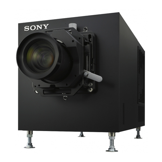
Page 5: Part Names And Functions
Part Names and Functions SRX-R515 Digital Cinema Projector Front a 8-inch duct attachment part c Lens attachment part Used to attach an 8-inch exhaust duct. Used to attach a separately-sold lens. b Lens fixing lever For further details, see “Attaching and Removing the Locks/unlocks the lens. -
Page 6: Status Indicators
d Status indicators When turning the power off Shows the status of the projector. Wait for the lamp’s cooling process to complete before turning the power switch off. For further details, see “How to Read the Indicators” (page 43). For further details, see “Shutting Down the System” (page 17). - Page 7 Connector block: Sub projector LKRA-010 a NETWORK connector (RJ-45 modular jack) i Link B IN connector Used to connect to the server’s PRJ connector with the Connect this connector on the sub projector to the supplied LAN cable. Link B OUT connector on the main projector. This connector is not used on the main projector.
-
Page 8: Xct-S10 Digital Cinema Server
For further details, see “How to Read the Indicators” A CRU DATAPORT carrier is necessary to use the (page 43). CRU DATAPORT. For further details, contact qualified Sony service personnel. d Ventilation holes (intake)/air filter For details on air filter cleaning, refer to the “Maintenance Manual.”... - Page 9 For use with separately-sold expansion power units. With both power units A and B attached, each can be used as a redundant power source. To connect a power unit, contact qualified Sony service personnel. h SPARE connector (RJ-45 modular jack) For future expansions.
-
Page 10: Lkra-007 Touch Panel Monitor
LKRA-007 Touch Panel Monitor Right side a MENU switch Caution Displays the menu. • When turning the power on, do not touch the touch b v / V switches panel monitor screen. Doing so may prevent normal Used for moving the menu and setting new values. operations after start-up. -
Page 11: Lkra-011 3D Filter And Holder
c TPC connector d Power input connector Used to connect to the server’s TPC connector with For connecting the supplied AC adapter. the supplied USB cable. For connection instructions, refer to the “Installation Manual.” LKRA-011 3D filter and holder (The 3D filters are installed to open to the left and right in the following sample illustration.) a Lock pin Locks the 3D filter holder. -
Page 12: Lkra-Pcab1 Projector Auto Calibration Box
LKRA-PCAB1 Projector Auto Calibration Box For details on how to use the LKRA-PCAB1, see “Calibrating the Screen” (page 35). Rear Front a Indicator B Indicates the system status of the LKRA-PCAB1. b Indicator A LCD panel Indicates that the hardware is initializing. Function area Various command c Calibration camera... -
Page 13: Main Screen
m CTRL2 connector l DC IN connector Connect the DC power cable of the supplied AC Use the supplied connection cable to connect this to adapter here. the RS-232C connector on the main projector. Main Screen a Auditorium number e Current SPL title If a computer is being used to control multiple f Progress bar auditoriums via a network, the auditorium numbers... - Page 14 k Error display button q Version information Displays the status of the device being controlled by Displays the version information of the projector. the server. r Projector information display When you tap the button, the “Error History” screen appears. Displays information about the projector. For details on the “Error History”...
-
Page 15: Items To Check
Logging Into the System Items to Check Caution It is necessary to pre-register as a user to log in to the projection system. Startup For further details, refer to the “Installation Manual.” When starting up the projection system, turn on the projectors’... -
Page 16: Starting The Projectors
Tap [Login]. Tap [OK] when the confirmation screen appears. Once you log in to the system, the “Status” screen will be displayed. Your password will be changed. Changing the login user on the upper right of the screen. Select [Logout], and then tap [OK]. Proceed to “Starting the Projectors”... -
Page 17: Shutting Down The System
When the main projector turns on, its MAIN, LAMP, Shutting Down the and IMB indicators will be solid green. When the sub projector turns on, its MAIN and System LAMP indicators will be solid green (its IMB indicator will remain red). on the upper right of the screen. -
Page 18: Operations
Operations Selecting the Projector to be Controlled Before performing a control operation, select the target Sequence of Operations projector. The sequence of operations from receiving distributed Tap the projector selection button at the top right of DCP to screening operations are shown below. the screen. -
Page 19: Ingesting Dcp
Ingesting DCP This procedure ingests DCP, such as the main feature to be screened, or previews, to the server. Notes • When DCP is encrypted, the KDM encryption key file is necessary. • Depending on the USB HDD type being used, the following messages may be displayed on the center of the screen. -
Page 20: Ingesting From Hdd Via Cru Dataport
Ingesting from HDD via CRU DATAPORT A CRU DATAPORT carrier is necessary to use the CRU DATAPORT. For further details, contact qualified Sony service personnel. The following operations are available for each button in Insert the HDD containing DCP to the server’s CRU the [Job List] pane. -
Page 21: Ingesting Via Network
To remove the HDD Ingesting KDM Perform the following to remove the HDD. When DCP is encrypted, it is necessary to also ingest the KDM encryption key file to the server. When DCP is encrypted, a key icon will be displayed on any CPL containing DCP. -
Page 22: Ingesting From A Network Folder
on how to remove an HDD, see “To remove the HDD” (page 21). Ingesting from a Network Folder If a KDM is copied to a preset network folder, it will be automatically ingested. For details on network folder settings, see the “Installation Manual”. -
Page 23: Playing Back Cpl
When KDM has not been ingested, “No Key” will be Playing Back CPL displayed. Calling up Screen Adjustment Data Depending on the content’s signal classification (viewing angle (HD/scope/flat)) for playback, screen adjustment data can be called up when registered in the function memory. -
Page 24: Selecting A Cpl
Tap [CLOSE] at the bottom of the screen to close the In the [Status] tab’s “Auditorium” screen, tap [Load]. screen. The lens mounted on the projector can be checked in the “Status” tab’s “Auditorium” screen. The “Load Content” screen will be displayed. Select the [CPL] radio button to display the “CPL”... -
Page 25: Playing Back Cpl
During CPL playback, the playback progress is displayed Playing Back CPL on the progress bar. Using buttons in the “Auditorium” screen, CPLs can be Progress bar played back, paused, or cued to a certain position, and they can be checked for missing files or damaged tracks. Control buttons Elapsed time (current position) Control buttons... -
Page 26: Creating An Spl
You can enter up to 128 alphanumeric characters and Creating an SPL symbols, excluding quotation marks ("). Create an SPL to show DCP in an auditorium. In an SPL, the screening order of a CPL for a single screening, and automatic controls for theater facilities during a screening are defined. - Page 27 Notes Caution • List operations can be carried out with the following When a cue has been inserted, you should check to see buttons. that the cue is executed before screening content. [I] / [i]: Changes the CPL or SPL order [Delete]: Deletes the selected CPL or SPL Note [Edit]: Changes the length of the black screen...
-
Page 28: Setting An Intermission In The Spl
In the SPL list, select the copy source, and then tap In the SPL list, select the SPL you want to add an [Copy]. intermission to, and then tap [Edit]. The SPL setting screen will be displayed. Enter the SPL title, and then tap [Apply]. Tap [Intermission Setup]. -
Page 29: Triggering Spl Playback Using Gpi Signals
6 Tap [Apply]. Note The intermission will be set. Tap [Details] to display detailed information on the selected SPL. Note Only one intermission can be set per SPL. Triggering SPL Playback Using GPI Signals You can use a GPI signal as a trigger to start playing back an SPL. -
Page 30: Playing Back An Spl
Playing Back an SPL Creating a Schedule Play back a created SPL. The schedule is a function that allows you to automatically This section describes steps for manual playback of SPLs. play back an SPL at a set time. For instructions on how to create a screening schedule, Note see “Creating a Schedule”... -
Page 31: Importing/Exporting Schedules
2 Select whether the schedule is a one-time event, this unit. For details on settings, refer to your or repeating. computer manual. To set a one-time event, select the [One Time] radio button, and to create a repeating schedule, To copy schedules select the [Repeat] radio button. -
Page 32: Projecting Images Using An External Playback Device
Select a schedule period to export, and then click Projecting Images Using [Apply]. an External Playback Device Images can be projected on a screen from a playback The schedule file is exported. device connected to the projector. Schedule files are normally stored in the downloads folder. -
Page 33: Manually Controlling Theater Facilities
Manually Controlling Theater Facilities Using touch panel monitor controls, you can control various theater facilities, such as opening and closing the curtain, and controlling the lights. It is necessary to make some initial connections and adjust settings to control theater facilities. For further details, refer to the “Installation Manual.”... -
Page 34: Others
Opening the 3D Filter Others Pull out the 3D filter in the direction of the arrow. Even if you pull the filter all the way out, it will not fall out of the holder due to the lock pin. Opening/Closing the 3D Filter Ordinarily, the 3D filters held in the 3D filter holders open and close on the left side of the projectors when viewed... -
Page 35: Calibrating The Screen
Connect the supplied connection cables as illustrated. Calibrating the Screen Main projector The LKRA-PCAB1 (herein referred to as the “calibration camera”) can be used to automatically calibrate deviations that may occur in the convergence between the two Sub projector projectors that comprise the dual system. You can perform calibration using the LCD panel and touch sensor via simple operations with each calibration operation taking about 5 minutes (when [STATIC] is selected for... -
Page 36: Lcd Panel Displays
e Function name The calibration camera turns on, and the following main menu appears in the LCD panel. During camera pass-through mode P C A B A “T” mark appears at the bottom right of the screen. The A L I G N M E N T aspect ratio of the image displayed during camera pass- U T I L I T Y through mode differs from that of the actual image and... -
Page 37: Performing Calibration
R E T U R N S E L E C T E X E C Sony service personnel. Check the ambient light. The calibration sequence will start according to the Make sure the area around the screen is as similar as mode and settings configured in [OPTION] - possible to the actual screening conditions. - Page 38 shorter with smaller shifts in the projected Tap F3 [START]. images. A L I G N M E N T > R E A D Y [AVERAGE]: Corrects distortions in both the sub projector and main projector’s projected images using the average amount of shifting between the two projectors as the target value, minimizing the amount of correction and improving the overlay accuracy between adjustment points.
-
Page 39: Disconnecting The Calibration Camera
Verify that the four areas in the test pattern displayed Tap F3 [ENTER]. on the calibration camera are not significantly askew. A L I G N M E N T > R E S U L T If they are significantly askew, make fine adjustments to the calibration camera’s position to achieve proper horizontal and vertical alignment. -
Page 40: Attaching And Removing The Lens
Disconnect the AC adapter from the calibration Attaching and Removing camera. the Lens Disconnect the connection cables from both projectors. Before changing the lens The projection system must be shut down, and the projector switch must be set to off before changing the lens. -
Page 41: Attaching The Lens
Remove the lens from the projector while firmly Lens fixing lever holding the lens not to drop it. Press. Lock button Attaching the Lens Confirm that the lens fixing lever is in the position. Raise the lever while holding down the lock button. - Page 42 Attach the lens to the projector while firmly holding Lens flange the lens not to drop it and aligning the position. Check that there are no gaps in each of the four locations (including reverse side). Shift base level Caution When attaching the lens to the projector, insert it straight.
-
Page 43: How To Read The Indicators
Projector (IMB section) (Status indicator) STATUS 1 Device status Solid red Start-up Solid orange Connecting to the server Solid green Connection to server complete STATUS 2 Device status Solid red IMB section error HDD2 Contact qualified Sony service HDD1 personnel POWER Solid green Normal... -
Page 44: Troubleshooting
If STATUS 1 indicator does not turn solid green even after a few minutes when connected to the server, contact Check this section before consulting qualified Sony qualified Sony service personnel. service personnel. If the unit still does not function properly, consult qualified Sony service personnel. - Page 45 Note Caution If the lamp is lit yellow or red, check the “Status – If you tap [Stop script], processing will stop and normal Auditorium” screen’s [Solution] message for a operation may be hindered. solution. Cannot shut down Unplug the power cord connected to the rear of the server. The projector switched to standby during playback When the projector switches to standby during playback...
-
Page 46: Error Code List (Lkra-Pcab1)
• Check the connection, and make Communication) connection cable is disconnected. sure the cable is connected properly. • The calibration camera is • Contact your local Sony malfunctioning. representative. ADJ:(Adjustment) NO SCREEN • The screen is not within the • Adjust the position of the... - Page 47 Error code Category Error message Possible cause Solution OUT OF SCREEN • The calibration camera’s position • Return to the main menu, and has shifted after its position and perform calibration again. zoom were adjusted. RE-FOCUS • The calibration points on the screen are not detected, even after the focus is fine-tuned.
-
Page 48: Specifications
Storage temperatures Specifications –20 °C to +60 °C (–4 °F to + 140 °F) Storage humidity 10% to 90% SRX-R515 Digital Cinema Projector* Supplied accessories • Key for removing housing (5) * The dual system consists of two of these projectors. •... -
Page 49: Lkra-007 Touch Panel Monitor
Conduit support mounting screws (4) recorded successfully. Mass Approx. 10 kg (Approx. 22 lb. 8.0 oz.) SONY WILL NOT BE LIABLE FOR DAMAGES OF (total weight of components) ANY KIND INCLUDING, BUT NOT LIMITED TO, Conduit length 4.7 m (5 yd. 5 in.) (excluding conduit... - Page 50 EXPIRATION OF THE WARRANTY, OR FOR ANY OTHER REASON WHATSOEVER. Top & Bottom 1920 × 1080 23.98p/24p • SONY WILL NOT BE LIABLE FOR CLAIMS OF Top & Bottom 1280 × 720 59.94p/60p ANY KIND MADE BY USERS OF THIS UNIT OR Top &...
- Page 51 Sony Corporation...