Sign In
Upload
Manuals
Brands
Viavi Manuals
Control Unit
T-BERD MTS 5800
Viavi T-BERD MTS 5800 Manuals
Manuals and User Guides for Viavi T-BERD MTS 5800. We have
21
Viavi T-BERD MTS 5800 manuals available for free PDF download: Getting Started Manual, User Manual, Quick Card, Quick Manual
Viavi T-BERD MTS 5800 Getting Started Manual (296 pages)
T-BERD/MTS/SC Getting Started Guide
Brand:
Viavi
| Category:
Test Equipment
| Size: 3.77 MB
Table of Contents
Table of Contents
7
About this Guide
18
Purpose and Scope
18
Assumptions
18
Terminology
18
Components
18
Transceivers
20
Line Rates and Signals
21
Related Information
21
Conventions
22
Safety and Compliance Information
24
Technical Assistance
24
Chapter 1 Overview
25
About the Instruments
26
Features and Capabilities
26
Configuring Your Instrument
28
What Ships with Your Instrument
28
Unpacking the Components
29
Inspecting the Components for Damage
30
Accessories
30
Optional Expansion Modules
31
About the T-BERD / MTS 5800 and SC 4800
32
Configuring the T-BERD / MTS 5800 and SC 4800
33
Exploring the SC 4800 and T-BERD / MTS 5800
35
Smart Class 4800
35
T-Berd / Mts 5800
37
About the CSAM Assembly
38
Exploring the CSAM Connector Panel
39
External Clock Reference and Clock Out/1Pps Connectors
40
CFP2 40/100G Connectors
40
QSFP+ 40G Connectors
40
MPO Connectivity
40
SFP+ Connectors
41
About the MSAM Assembly
41
MSAM Chassis
43
SMA Connector
44
USB Connector
44
Msam Pims
44
Restrictions
48
About the DMC Assembly
48
Base Unit Requirements
48
Restrictions
49
Viavi Recommended Optical Adapters and Transceivers
49
Chapter 2 Assembling Your Instrument
51
Preparing for Assembly
52
Connecting a DMC to a Base Unit
52
Key Principles
52
Verifying the Base Unit Requirements
52
Required Tools
53
Connecting the Components
54
Connecting Two Dmcs to a Base Unit
57
Disconnecting the DMC
57
Disassembling the Instrument
57
Required Tools
57
Inserting Msams or Csams into the 6000A Base Unit or DMC
59
MSAM Requirements
59
CSAM Requirements
59
Required Tools
59
Inserting the MSAM or CSAM
59
Inserting, Removing, and Swapping Pims in the MSAM
61
Inserting a PIM
61
Removing a PIM
63
Swapping Pims
64
Attaching an Expansion Module to the 5800V2/100G and 5882
64
Handling CFP Adapters and Transceivers
67
Inserting a CFP Adapter
67
Inserting a CFP, CFP2, or CFP4 Transceiver
69
Removing a CFP, CFP2, or CFP4 Transceiver
71
Handling SFP/SFP+, XFP, and QSFP+ Transceivers
72
Inserting an SFP/SFP+, XFP, or QSFP+ Transceiver
72
Removing an SFP/SFP+, XFP, or QSFP+ Transceiver
74
Attaching an External Optical Connector
75
Disconnecting the DMC
76
Required Tools
76
Disassembling the Instrument
76
Chapter 3 Getting Started
79
Powering the Instrument
80
Verifying that You Have the Correct Adapter
80
Using the AC Power Adapter
83
Turning on the Instrument
83
Turning off the Instrument
83
Charging the Battery
83
6000A Charge LED
84
Launching the MSAM or CSAM
84
Multiple BERT Icons
84
About the Jitter Icon
85
Turning the BERT Icon on
85
Navigating the User Interface
86
Menu Bar
87
Soft Keys
87
Setup/Results
88
Menu Keys
88
Test Bar
88
Message Box
89
Quick Config Settings
89
Signal Structure
90
LED Panel
90
Current and History Leds
91
LED Colors
91
10 Gigabit Ethernet WAN Leds
92
Leds for Muxed Payloads
92
Actions Panel
92
Result Buttons
93
Result Windows
93
Setting up the Instrument
94
Specifying International Settings
94
Setting the Date and Time
95
MSAM and CSAM
95
T-BERD / MTS 5800 and SC 4800
95
Changing the Remote Access Password
96
Checking the Battery
96
Setting up the Display
97
Adjusting Screen Brightness
97
Setting up the Screen Saver
97
Customizing the User Interface Look and Feel
98
ANT Mode
98
Specifying the LED Results Mode
98
Testpad Mode
98
Viewing or Installing Options
99
Loading Upgrades
100
Synchronizing to the Stratasync Server
101
Specifying a Printer for the Instrument
103
Connecting Your Instrument to the Circuit
103
Configuring Expert Optical Settings
104
Browsing the Web
107
Connecting to Wifi
107
Playing Videos
108
Setting up the Job Manager
109
To Specify Report Information
109
Job Manager Test Plan86
110
Chapter 4 Basic Testing
113
Preparing to Test
114
Understanding Synchronization Requirements
114
ATP-GPS Test Packets
114
About CDMA Receivers
115
About GPS Receivers
116
Connecting the GPS Receiver to Your Instrument
117
Configuring GPS as the Time Source
122
Understanding External High Accuracy Timing References
122
Preparing for Optical Testing
123
Considerations
123
Tuning SFP+ and XFP Transceivers
124
Verifying Supported Line Rates
124
Testing Optics and Cables
126
5800-100G and 5800V2
127
Running the Optics Self-Test and Cable Test
127
Generating Reports
131
Step 1: Selecting a Test Application
133
About the Quick Launch Screen
133
Pinned Tests
134
Recently Selected Tests
134
Customizing the Quick Launch Screen
135
Launching a Test from the Quick Launch Screen
135
Launching a Test Using the Test Menu
136
Step 2: Configuring a Test
137
Displaying the Setup Screens
137
Entering Data in the Setup Fields
138
Saving Setups
138
Understanding Write-Protected Configurations
139
Step 3: Connecting the Instrument to the Circuit
139
Step 4: Starting the Test
139
Using the Action Buttons
140
Controlling Laser Transmission
140
Restarting a Test
141
Step 5: Viewing Test Results
142
Setting the Result Group and Category
142
Expanding and Collapsing Result Measurements
143
Changing the Result Layout
143
Using the Entire Screen for Results
144
Setting the Blink Option on Errors
144
About Histogram Results
145
Viewing a Histogram
145
About the Event Log
146
Viewing an Event Log
146
About Result Graphs
147
Viewing Graphs
147
Clearing History Results
148
Creating and Maintaining Custom Result Groups
148
Running Multiple Tests
149
Restrictions
150
Running Multiple Tests
151
Viewing both Tests
153
Scheduling Timed Tests
155
Creating and Printing Reports
155
Including a Logo in Your Reports
156
Specifying Report Details
156
Creating a Report
157
Printing Reports
158
Generating Reports Automatically
159
Viewing a Report
160
Accessing Test Reports Remotely
161
Exporting Reports
161
Restoring Test Defaults
162
VT-100 Emulation
162
Establishing a Serial Connection
162
Running a VT-100 Session
163
Saving Terminal Screen Data
164
HTML Viewer
165
Launching the Viewer
165
Navigating Using the Viewer
165
Finding Text on a Page
165
Scrolling
165
Going Back or Forward One Pages
166
Going Home
166
Selecting Links
166
Exiting the Viewer
166
Chapter 5 Smart Access Anywhere
167
About Smart Access Anywhere
168
Licensing
168
Downloading and Extracting the Utility
168
Establishing a Connection
169
Wired Ethernet Connection
169
Wifi Connection
170
Smartphone with Data Tethering
170
Launching the Utility
171
Launching the Utility on the Instrument
171
Testing Your Connection
171
Launching the Utility on Your Workstation
172
Displaying the Instrument's User Interface
172
Transferring Files
173
Displaying and Modifying Connection Settings
173
Chapter 6 Using Bluetooth Connections
175
Setting up a Bluetooth Connection
176
Transferring Files Via Bluetooth
177
Using a Bluetooth Audio Device
178
Disconnecting and Unpairing Bluetooth Devices
179
Deactivating Bluetooth
180
Chapter 7 Optical Tools
181
About the Optical Tools
182
Inspecting Fiber
182
Measuring Optical Power
184
Appendix A Specifications
185
T-BERD / MTS 5800 and Smart Class 4800 Specifications
186
Physical Specifications
186
Power Specifications
187
Electrical Ethernet Specifications
187
Clock Source (Timing) Specifications
187
DS1 Specifications
188
Receiver
189
Transmitter
189
Physical Measurements
190
E1 Specifications
190
E1 (RJ-48) Specifications
191
Receiver (RJ-48)
191
Transmitter (RJ-48)
191
E3/DS3/STS-1 Specifications (5800 Family of Instruments Only)
192
Receiver (E3 Circuits)
192
Transmitter (E3 Circuits)
193
Level Measurements (E3 Circuits)
193
Receiver (DS3 Circuits)
193
Transmitter (DS3 Circuits)
194
Physical Measurements (DS3 Circuits)
195
Receiver (STS-1 Circuits)
195
Transmitter (STS-1 Circuits)
195
Physical Measurements (STS-1 Circuits)
196
E4/STM-1E Specifications (5800 Family of Instruments Only)
196
Receiver (E4 Circuits)
197
Transmitter (E4 Circuits)
197
Physical Measurements (E4 Circuits)
197
Receiver (STM-1E Circuits)
198
Transmitter (STM-1E Circuits)
198
Physical Measurements (STM-1E Circuits)
199
SFP/SFP+/SFP28 Specifications
199
Supported Optical Rates
199
CFP4 and QSFP+/QSFP28 Specifications for 5800-100G
200
CFP4 Interface
200
Optical Specifications
200
QSFP+/QSFP28 Interface
200
Optional Expansion Module Specifications
201
OTDR Modules
201
TEM Module
201
Internal GNSS Application for T-BERD / MTS 5800-100G and 5882
201
MSAM Specifications
201
Battery Specifications
202
Clock Input Interface Specifications
202
HS Datacom PIM Specifications
202
Physical Specifications
202
Power Supply Specifications
202
Clock Output Interface Specifications
203
Internal Synthesizer Specifications
204
X.21 Interface Specifications
204
RS-232/V.24 Interface Specifications
206
EIA-530/EIA-530A Balanced Interface Specifications
208
EIA-530/EIA-530A Unbalanced Interface Specifications
211
MIL-188C Interface Specifications
213
V.35 Interface Specifications
215
MIL-188-114 Interface Specifications
220
Diphase PIM Specifications
222
DS1 PIM Specifications
223
Receiver
223
Physical Measurements
224
Transmitter
224
E1 (BNC) PIM Specifications
225
Receiver (BNC)
225
E1 (RJ-48) PIM Specifications
226
Receiver (RJ-48)
226
Transmitter (BNC)
226
Transmitter (RJ-48)
227
E3/DS3/STS-1 PIM Specifications
228
Receiver (E3 Circuits)
228
Transmitter (E3 Circuits)
228
Level Measurements (E3 Circuits)
229
Receiver (DS3 Circuits)
229
Transmitter (DS3 Circuits)
229
Physical Measurements (DS3 Circuits)
230
Receiver (STS-1 Circuits)
230
E4/STM-1E PIM Specifications
231
Physical Measurements (STS-1 Circuits)
231
Transmitter (STS-1 Circuits)
231
Receiver (E4 Circuits)
232
Transmitter (E4 Circuits)
232
Physical Measurements (E4 Circuits)
233
Receiver (STM-1E Circuits)
233
Transmitter (STM-1E Circuits)
233
Interface Specifications- Jitter and Wander Applications
234
Physical Measurements (STM-1E Circuits)
234
SFP PIM Specifications
234
Supported Electrical Rates
234
Electrical Interface Specifications
235
Supported Optical Rates
235
XFP PIM Specifications
235
Clock Source (Timing) Specifications
236
Optical Specifications
236
DS1 Electrical Specifications
236
Receivers
236
Physical Measurements
237
Transmitter
237
E1 (2M) Electrical Specifications
238
Receivers
238
Transmitters
239
E3 Electrical Specifications
240
Receiver
240
Transmitter
240
Level Measurements
241
DS3 Electrical Specifications
241
Receivers
241
Transmitter
241
Physical Measurements
242
STS-1 Electrical Specifications
242
Receivers
243
Transmitter
243
Physical Measurements
244
E4 Electrical Specifications
244
Receiver
244
Transmitter
244
Physical Measurements
245
STM-1 Electrical Specifications
245
Receiver
245
Physical Measurements
246
Transmitter
246
10/100/1000Base T Electrical Specifications
246
Optical Interface Specifications
246
Jitter and Wander Specifications
248
Electrical Jitter and Wander Specifications
248
Jitter Analyzer
249
Jitter Generator
249
Standards
249
Automatic Jitter Measurements
251
Wander Generator
252
Wander Measurement
253
Interface Specifications (Jitter and Wander Applications)
254
Memory Requirements
254
Optical Jitter and Wander Specifications
255
Jitter Analyzer
256
Jitter Generator
256
Standards
256
Automatic Jitter Measurements
260
Wander Generator
260
Wander Measurement
261
Memory Requirements
263
CSAM Specifications
263
Physical Specifications
263
Power Supply Specifications
263
Battery Specifications
264
CFP2 Interface
264
Optical Specifications
264
QSFP+ Interface
264
DMC Specifications
265
Physical Specifications
265
Power Supply Specifications
265
SFP+ Interface
265
Battery Specifications
266
Environmental Specifications
266
T-BERD / MTS 5800 and SC 4800 Environmental Specifications
266
Transceiver and Adapter Specifications
266
MSAM Environmental Specifications
267
Maintaining the T-BERD/MTS 5800 and SC 4800 Batteries
269
Appendix B Maintenance and Troubleshooting245
269
Guidelines
269
Appendix B Maintenance and Troubleshooting Maintaining the T-BERD/MTS 5800 and SC 4800 Batteries
270
Recharging the Battery
270
Replacing the T-BERD / MTS 5800 and SC 4800 Batteries
271
Calibrating the T-BERD / MTS 5800 and SC 4800 Touchscreen
271
Viewing the System Info
272
Enabling Software Options
272
Locating the Option Challenge ID
272
Enabling the Software Option
273
Updating the Software
273
Downloading Software to a USB
273
Extracting the Software to a USB Stick
274
Installing the Software Using a USB Stick
275
Reimage Software Using a USB Stick
275
Updating over a Network Connection
276
Retrograding the Software
277
About Troubleshooting
277
Assembly and Setup
278
Which Transceivers Are Compatible with the Instrument
278
Can I Hot-Swap Msams and Csams
278
Can I Hot-Swap Pims
278
Can I Hot-Swap Transceivers
278
Can I Do Dual Port Testing from a Single SFP PIM
278
No Signal Is Detected When Running 10 Gige Application
278
Operating the Instrument
279
How Much Space Is Available for My Data
279
Instrument will Not Power up
280
Can Not Print Test Results
280
Instrument Shows an Unused Slot
280
Instrument Does Not Recognize USB Stick
280
Performing Tests
281
Test Menu Does Not Appear
281
Application Does Not Appear on the Test Menu
281
Optical Overload Protection Is Activated
281
MSAM or CSAM User Interface Is Not Launching
281
Test Results Are Inconsistent
282
Result Values Are Blank
283
No RFC 2544 or FC Test Buttons Appear
283
Maintaining Your Instrument
283
How Often Does the Instrument Need to be Calibrated
283
What Are the Insertion Rates for All Components
283
Battery Communication
284
Appendix C Storage and Shipment
285
Storing the Instrument
286
Environmental Specifications
286
Shipping the Your Instrument
286
Removing the Component
286
Packing the Components
287
Returning Equipment to Viavi
287
Glossary
289
Advertisement
Viavi T-BERD MTS 5800 User Manual (100 pages)
Timing Expansion Module (TEM)
Brand:
Viavi
| Category:
Control Unit
| Size: 1.37 MB
Table of Contents
Table of Contents
7
Assumptions
12
Purpose and Scope
12
Terminology
12
Conventions
13
Related Information
13
Safety and Compliance Information
16
Technical Assistance
16
Overview
17
Chapter 1 Overview
17
About the TEM Module
18
Features and Capabilities
18
What Ships with the TEM Module
19
Unpacking the Components
20
Inspecting the Components for Damage
20
Exploring the TEM Module Connector Panel
21
Getting Started
23
Chapter 2 Getting Started
23
Connecting the TEM Module to Your Test Instrument
24
Connecting a GNSS Antenna
26
Powering the TEM Module
27
Verifying that You Have the Correct Adapter
28
Using the AC Power Adapter
28
Turning on the Instrument
29
Checking the Battery
29
Verifying the Local Time Zone
29
Turning on the Rubidium Oscillator
30
Navigating the TEM Module User Interface
31
Timing Module Tab
32
Setup/Results Soft Key
33
Message Bar
33
LED Panel
33
Current and History Leds
33
LED Colors
33
Action Buttons
33
Result Buttons
34
Turning off the Rubidium Oscillator
35
Turning off the Instrument
35
Disconnecting a GNSS Antenna
35
Disconnecting the TEM Module
36
High Accuracy Timing
37
Chapter 3 High Accuracy Timing
37
Basic Timing Principles
38
GNSS Timing
38
Satellite Based Augmentation Systems
38
GNSS Antennas
38
Available Survey Modes
39
Fixed Position Mode
40
Receiver Modes
40
Resynchronizing GNSS Time
40
External 1 PPS and 10 Mhz Timing
41
External BITS/SETS Timing
41
Holdover Mode
41
Common Test Applications
42
Precision Time Protocol (PTP) Measurements
42
PTP Delay
42
PTP Delay Symmetry
43
PTP Time Errors
43
One Way Delay Measurements
43
Wander and Jitter Analysis
43
Warming up the Oscillator
44
Configuring the Module
45
Specifying Oscillator and Timing Settings
45
Specifying GNSS Settings
46
Specifying Location Settings
47
Survey Settings
47
Fixed Position Settings
48
Saving Location Coordinates
49
Surveying GNSS Constellations
50
Resetting the Start Location
50
Tuning the Oscillator
50
Tuning to an External Reference Clock or Signal
51
Tuning to the Internal GNSS Receiver
51
Forcing the Oscillator into Holdover Mode
51
Qualifying GNSS Antennas
52
Chapter 4 1PPS Wander Analysis
55
About 1PPS Wander Analysis
56
Signal Input
56
Leds and Test Results
56
Impact on Oscillator Tuning
57
Monitoring Oscillator Drift
57
Using a GNSS Tuned Oscillator
57
Measuring TIE and Calculating MTIE/TDEV
58
Analyzing 1PPS Wander
60
Saving and Exporting TIE Measurement Data
62
Chapter 5 Timing and 1 PPS Analysis Results
65
About TEM Module Timing and 1 PPS Analysis Results
66
Leds
66
Oscillator Leds
66
GNSS Leds
67
Event Log
67
Satellite Results
68
Sky Plot
69
Signal Strength
70
CNO Map Spectrogram and CNO Map Table
70
GNSS Results
71
Status
72
Location
72
Time
73
Oscillator Results
74
PPS Analysis Results
75
Tod Results
75
Chapter 6 Troubleshooting
77
Troubleshooting about Troubleshooting
78
About Troubleshooting
78
No GNSS Time Is Detected
79
No GNSS Satellites Are Located
79
Assembly and Setup
78
Can I Hot-Swap the TEM Module
78
Can I Hot-Swap GNSS Antennas
78
Operating the TEM Module
78
TEM Module Is Not Recognized
78
Oscillator Leds Are Not Illuminated
78
Performing Tests
79
Application Does Not Appear on the Test Menu
80
Test Results Are Inconsistent
80
Result Values Are Unavailable
80
Can I Use the TEM Module to Support Dual Port Testing
80
Maintaining Your TEM Module
80
Does the Module Need to be Calibrated
81
Appendix A Specifications
83
About the TEM Module Specifications
84
Physical Specifications
84
Environmental Specifications
84
Power Specifications
85
Connector Specifications
85
SMA Connector
85
SMB Connectors
85
Performance Specifications
86
GNSS Specifications
86
Time Specifications
86
Oscillator Specifications
87
PPS Analysis Specifications
87
Appendix B Storage and Shipment
89
Storing the Instrument and Module
90
Using the Instrument and Module after Prolonged Storage
90
Transporting Your TEM Module
90
Shipping Your TEM Module
91
Disconnecting the Components
91
Packing the Components
91
Returning Equipment to Viavi
91
Glossary
93
Viavi T-BERD MTS 5800 Quick Manual (5 pages)
Network Tester CPRI Check, RRU Testing with ALU BBU Emulation and RF over CPRI Spectrum Analysis
Brand:
Viavi
| Category:
Test Equipment
| Size: 0.93 MB
Table of Contents
Equipment Requirements
1
Information Requirements
1
Fiber Inspection Guidelines
1
Connect to Fiber under Test
2
Launch Test
2
Configure Test
2
Configure RRH Transmit and Receive Settings
3
Local SFP Verification
3
Run Test
3
Detailed Results for each Completed Test
4
Run the RET Test
4
Run the VSWR Test
4
Run the Diversity Imbalance Test
4
Run the PIM Detect Test
5
Run the 2-Tone PIM Detect Test
5
Save Report
5
Advertisement
Viavi T-BERD MTS 5800 Quick Card (5 pages)
Modular Test Set, E4100 Module EXPERT OTDR Quick Setup
Brand:
Viavi
| Category:
Test Equipment
| Size: 1.04 MB
Table of Contents
Equipment Requirements
1
Fiber Inspection Guidelines
1
Connect the Launch Cable to the OTDR Port
2
Connect to Fiber under Test (FUT)
2
Launch and Configure Test
2
Run Test
3
Trace View
4
Smartlink View
4
Table View
5
Fast Report
5
Viavi T-BERD MTS 5800 Quick Card (4 pages)
Network Tester, Ethernet Layer 3 Multicast Traffic Analysis
Brand:
Viavi
| Category:
Test Equipment
| Size: 1.04 MB
Table of Contents
Equipment Requirements
1
Fiber Inspection Guidelines
1
Connect to Fiber under Test (FUT)
2
Launch and Configure Test
2
IP Settings
3
IGMP Settings
3
Address Book
3
Join Multicast Groups
4
Analyze Multicast Traffic
4
Viavi T-BERD MTS 5800 Quick Card (4 pages)
Network Tester One Way Delay (OWD) Measurement
Brand:
Viavi
| Category:
Network Cable
| Size: 1.47 MB
Table of Contents
Equipment Requirements
1
Fiber Inspection Guidelines
1
Connect each T-BERD to Port under Test
2
Launch and Configure Tests
2
Verify Tod Sync and 1 PPS Sync Leds
3
Configure Ethernet Settings
3
Configure Traffic Settings
4
Results Verification
4
One Way Delay Results
4
Viavi T-BERD MTS 5800 Quick Card (4 pages)
Network Tester: CPRI Check, Dark Fiber and WDM Loopback Testing
Brand:
Viavi
| Category:
Test Equipment
| Size: 0.75 MB
Table of Contents
Equipment Requirements
1
Information Requirements
1
Fiber Inspection Guidelines
2
Connect to Fiber under Test
2
Launch Test
2
Configure Test
3
Run Test
4
Save Report
4
Viavi T-BERD MTS 5800 Quick Card (4 pages)
Network Tester, Ethernet Layer 3 IPv4 Traffic Loopback
Brand:
Viavi
| Category:
Test Equipment
| Size: 1.06 MB
Table of Contents
Equipment Requirements
1
Fiber Inspection Guidelines
1
Connect to Line under Test
2
Launch and Configure Test
3
Ethernet Settings
4
IP Settings
4
Results Soft Key
4
Viavi T-BERD MTS 5800 Quick Card (4 pages)
Network Tester
Brand:
Viavi
| Category:
Test Equipment
| Size: 1.2 MB
Table of Contents
Equipment Requirements
1
Fiber Inspection Guidelines
1
Connect to Fiber under Test (FUT)
2
Launch and Configure Test
2
IP Settings
3
Results Screen
4
Summary Results
4
Viavi T-BERD MTS 5800 Quick Card (5 pages)
Network Tester, Ethernet RFC 2544 Layer 3 Traffic
Brand:
Viavi
| Category:
Test Equipment
| Size: 1.08 MB
Table of Contents
Equipment Requirements
1
Fiber Inspection Guidelines
1
Connect to Fiber under Test (FUT)
2
Launch Test
2
Configure Test
3
Run Test
5
Viavi T-BERD MTS 5800 Quick Card (3 pages)
Network Tester CPRI Check, RRU Connectivity Testing
Brand:
Viavi
| Category:
Network Cable
| Size: 0.59 MB
Table of Contents
Equipment Requirements
1
Information Requirements
1
Fiber Inspection Guidelines
1
Connect to Fiber under Test
2
Launch Test
2
Configure Test
2
Run Test
3
Save Report
3
Viavi T-BERD MTS 5800 Quick Card (3 pages)
Network Tester
Brand:
Viavi
| Category:
Test Equipment
| Size: 0.9 MB
Table of Contents
Equipment Requirements
1
Connect the GNSS Antenna
1
Enable GNSS Receiver and Complete Survey
2
Configure GNSS Settings
2
Configure Location Settings
2
Using the Results Group and Category Drop-Down Menus
3
Perform Timing Tests Using the Attached Antenna
3
Viavi T-BERD MTS 5800 Quick Card (3 pages)
Network Tester GNSS Reception Test
Brand:
Viavi
| Category:
Network Cable
| Size: 0.78 MB
Table of Contents
Equipment Requirements
1
T-BERD/MTS Placement and GNSS Antenna Connection
1
Configure GNSS Reception Test
2
Run GNSS Reception Test
2
GNSS Status Results
3
Satellites Sky Plot Results
3
GNSS Location and Satellites CNO Map Spectrogram Results
3
Viavi T-BERD MTS 5800 Quick Card (4 pages)
Modular Test Set FTTA OTDR, Cell Tower Maintenance
Brand:
Viavi
| Category:
Network Cable
| Size: 0.62 MB
Table of Contents
Equipment Requirements
1
Fiber Inspection Guidelines
1
Connect to Fiber under Test (FUT)
2
Launch Test
3
Run Test
4
Viavi T-BERD MTS 5800 Quick Card (3 pages)
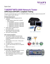
Network Tester, CPRI Check SFP/SFP+ Loopback Testing
Brand:
Viavi
| Category:
Test Equipment
| Size: 0.65 MB
Table of Contents
Equipment Requirements
1
Fiber Inspection Guidelines
1
Connect Optics under Test
1
Launch Test
2
Configure Test
2
Run Test
3
Viavi T-BERD MTS 5800 Quick Card (3 pages)
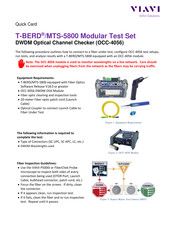
Modular Test Set, DWDM Optical Channel Checker
Brand:
Viavi
| Category:
Test Equipment
| Size: 0.79 MB
Table of Contents
Equipment Requirements
1
Fiber Inspection Guidelines
1
Connect to Fiber under Test (FUT)
2
Setup Test
3
Run Test
3
Viavi T-BERD MTS 5800 Quick Card (3 pages)
Network Tester Ethernet Packet Capture/Decode in Copper RJ-45 10/100/1000 Dual Through Mode
Brand:
Viavi
| Category:
Network Cable
| Size: 1.01 MB
Table of Contents
Equipment Requirements
1
Connect to Line under Test
1
Launch Test
2
Configure Test
2
Packet Capture/Decode
3
Viavi T-BERD MTS 5800 Quick Card (2 pages)
Measuring Light Levels with the MP-60 and MP-80 Optical Power Meters
Brand:
Viavi
| Category:
Measuring Instruments
| Size: 0.36 MB
Table of Contents
Equipment Requirements
1
Required Information for Testing
1
Fiber Inspection Guidelines
1
Connect to the Fiber under Test
1
Connect to the Fiber or Light Source under Test
2
Measure Absolute Power
2
Viavi T-BERD MTS 5800 Quick Card (3 pages)
Modular Test Set, E4100 OTDR Module Optical Light Source Option
Brand:
Viavi
| Category:
Test Equipment
| Size: 0.55 MB
Table of Contents
Equipment Requirements
1
Fiber Inspection Guidelines
1
Connect to Fiber under Test (FUT)
2
Operate the Light Source
2
Viavi T-BERD MTS 5800 Quick Card (6 pages)
Handheld Network Tester
Brand:
Viavi
| Category:
Test Equipment
| Size: 1.5 MB
Viavi T-BERD MTS 5800 Quick Card (4 pages)
Modular Test Set
Brand:
Viavi
| Category:
Test Equipment
| Size: 1.21 MB
Advertisement
Related Products
Viavi mA-3011
Viavi mA-3A01
Viavi MSAM
Viavi T-BERD 5800
Viavi T-BERD/MTS- 2000V2
Viavi T-BERD/MTS-5800V2
Viavi MTS 4000 Base Unit
Viavi MTS 2000
Viavi T-BERD MTS 5800-100G
Viavi MTS 8000
Viavi Categories
Test Equipment
Measuring Instruments
Control Unit
Microscope
Server
More Viavi Manuals
Login
Sign In
OR
Sign in with Facebook
Sign in with Google
Upload manual
Upload from disk
Upload from URL