Sign In
Upload
Manuals
Brands
Viavi Manuals
Test Equipment
MTS 8000
Viavi MTS 8000 Manuals
Manuals and User Guides for Viavi MTS 8000. We have
1
Viavi MTS 8000 manual available for free PDF download: User Manual
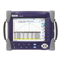
Viavi MTS 8000 User Manual (660 pages)
Scalable Multitest Platform
Brand:
Viavi
| Category:
Test Equipment
| Size: 5.52 MB
Table of Contents
Table of Contents
7
About this Guide
30
Purpose and Scope
30
Assumptions
30
Technical Assistance
30
Recycling Information
30
Conventions
31
Principles of Measurement
35
Chapter 1 Principles of Measurement
35
Principle of Reflectometry Measurements
36
Information Yielded by the Measurement
36
Validity of Measurement
37
Reflectance
37
Principle of Bi-Directional Measurement
39
Principle of the Optical Power and Attenuation Measurements
40
Power Measurement
40
Attenuation Measurements (Optical Link Loss)
40
PMD Principle
42
Method Used to Measure the PMD
43
Principle of Measurement of Chromatic Dispersion (CD ODM) Using Phase Shift Method
44
Standards and L0 for Different Types of Fiber
45
Getting Started
47
Chapter 2 Getting Started
47
Unpacking the Device - Precautions
48
Installing a Module in a Receptacle and Removing It
48
Inserting a Module
49
Removing a Module
49
Connecting Fiber Optic Cable
50
Inspecting and Cleaning Connector End Faces
50
Optical Connector Types
51
Connecting Fiber Optic Cable to Test Port
53
Optical Connectors and Interchangeable Adapters
54
Adapter Types
54
Switching Adapter Type
55
Cleaning the Universal Connector
55
Display Screen
56
Top Status Bar
57
Mini-Trace
57
Signature of the Measurement
58
Main Display Zone
58
Tabs
58
Soft Keys
59
Icons
60
Selection Keys
60
Reflectometry Measurements
61
Chapter 3 Reflectometry Measurements
61
Activating the OTDR Function
62
Selecting the Smart Test Function
62
Principle of the Smart Test
62
Selecting Smart Test
62
Selecting the Expert OTDR Function
64
Principle of the Expert OTDR
64
Selecting Expert OTDR
64
Configuring the Reflectometry Test
65
Configuring the Unit for Smart Test
65
Selecting the Configuration File
65
Modifying some Parameters before the Acquisition
66
Configuring the Test in Expert OTDR
68
Configuring the Acquisition Parameters
69
Configuring the Alarms Parameters
74
Configuring the Analysis Parameters
76
Configuring the Link Parameters
82
Configuring the File Parameters
89
Configuration in Test Auto Mode
93
Saving OTDR Configuration in a File
95
Loading an Existing OTDR Configuration File
96
Traffic Detection and Connection Quality Indicator
98
Traffic Detection
98
Connection Quality Indicator
98
Performing OTDR Acquisitions
99
Acquisition in Real Time Mode
100
Performing an Acquisition in Real Time Mode
100
Principle of Real Time Mode
100
Stopping the Real Time Acquisition
101
Performing a Measurement with Smart Test
101
Performing an Acquisition with Expert OTDR
103
Performing an Acquisition from Results Page
104
Multi-Wavelength Acquisition
105
Actions on Trace During Acquisition
106
Results Display
109
Common Functions
111
Display of Events on the Trace
111
Results Table
112
Cursors
116
Zoom Function
118
Shift Function (Expert OTDR Only)
121
Summary
121
Display of Traces in Overlay
123
Traces Display in Double Acquisition Mode
124
Advanced Functions in Expert OTDR Mode
125
Automatic Measurement and Detection
125
Addition of Events
126
Modifying Types of Events
128
Relative Measurement
128
Table Notes
130
Manual Measurements
132
Measurements of Slope
132
Measurement of ORL
134
Measurement of Reflectance
135
Splice Measurements
136
Memorization of the Position of Events
138
Overlay Trace Function
139
Display of Traces in Overlay
140
Overlaying Several Traces Stored in Memory
140
Adding Traces in Overlay
141
Swapping Overlay Traces
141
Changing the Traces Position
142
Removing a Trace
142
Quitting the Overlay Menu
143
Reference Trace Function
143
Using the Reference Trace Function in the Result Page
143
Using the Reference Trace Function in the Explorer
144
Saving the Trace(S) and Generating a Report
145
Saving Results and Creating a Report from Results Page
145
Opening a Report
148
Recalling OTDR Files
150
SLM (Smart Link Mapper) Option
150
Show the Detailed Information of One Event
152
Event View
153
Changing the Type of an Event
154
Optipulses Option
156
Configuring the OTDR Acquisition with Optipulses Mode
156
Results in Optipulses Mode
157
FTTA-SLM Option
159
Principle of FTTA-SLM
159
Acceptance Testing
160
Troubleshooting Testing
161
Configuring the Reflectometry Test for FTTA Network
162
FTTA Setup
163
Alarms Parameters
165
Analysis
166
Link Description
167
File Parameters
169
Launching the Acquisition
171
Results Page
172
Trace View
172
Smartlink View
174
Changing the Name of an Event
179
FTTH-SLM Software Option
180
Principle of FTTH
180
Configuring the Reflectometry Test for FTTH Network
181
FTTH Setup
182
Alarms Parameters
184
Link Parameters
186
File Parameters
187
Launching the Acquisition
189
Results Page
190
Trace View
191
Smartlink View
192
Changing the Type of an Event
196
Smart Link Cable Option
198
Principle of Smart Link Cable
198
Configuring the Smart Link Cable Project
199
Configuring the Project
199
Saving the Project
200
Loading an Existing Project
201
Starting Project Test Process
202
Trace Saving
203
Results of Project Cable
204
Deactivate the Fiber Test
204
Description of the Table
204
View Trace
205
Files and Project Storage
206
Text File Content
208
Reduced Dead Zone OTDR Application
209
Chapter 4 Reduced Dead Zone OTDR Application
210
Acquisition Parameters
211
Description of the RDZ Function
210
Selecting and Configuring the RDZ Function
210
Performing the Measurement
213
Performing an Acquisition from Results Page
214
Results Display
215
SLM View
218
Saving the Trace(S) and Generating a Report
218
Saving Results and Creating a Report from Results Page
219
Opening a Report
222
Chapter 5 Power Meter and Source Functions of the OTDR Modules
226
Connection to the Power Meter and the Source
226
Configuring the Power Meter
226
Configuring the Measurement Parameters of the Power Meter
226
Configuring the Alarm Parameters of the Power Meter
227
Configuring the Measurement Parameters
228
Activating the Source Function
229
Result Page
229
Result Page of the Power Meter
230
Table of Results
230
Commands of the Power Meter Parameters
231
Result Page of the Source
232
Performing the Power Level Measurement
234
Performing the Insertion Loss Measurement
234
Setting the Zero Value of the Power Meter
235
Carrying out the Reference
235
Carrying out the Side by Side Reference
235
Carrying out the Reference in Loopback Mode
237
Measurements on the Fiber under Test
238
Storing and Reloading Results
239
File Setup
239
Storing Results
239
Loading Results
240
Bi-Directional OTDR
241
Chapter 6 Bi-Directional OTDR
241
Definition of Terms Used
242
Description of the Measurement
242
Summary of the Automatic Operation Procedure
244
Configuration of Bi-Directional Measurement
244
Acquisition Parameters
245
Alarms Parameters
246
Configuration of Files Parameters
246
Performing a Bi-Directional Measurement
247
Process Display
247
Fiber Link Check
250
Measurement Process
250
Trace Display Functions
253
Origin and End Traces
254
OEO Trace
255
OEO Result Table
255
Automatic Measurement and Addition of Markers in OEO Page
256
Key Delete/Auto Meas
256
Addition of Markers
256
Markers Display
257
Test of a Cable
257
Saving the Traces and Generating a Report
258
Saving Results and Creating a Report from Results Page
258
Opening a Report
260
Recalling OEO Traces
262
Troubleshooting
263
Warning/Errors after Pressing the Key START
263
Warning/Errors Resulting from Common Configurations
264
Chapter 7 Fibercomplete Modules
265
Fibercomplete Modules
266
General Introduction
266
Principle
266
Configurations
267
Activating the Function
269
Establishing References
270
Reference Stage Process
271
Loopback Referencing Method
272
Side-By-Side Referencing Method
274
Factory References
276
Configuring the Units
276
Acquisition Parameters
277
Alarms Parameters
279
Analysis Parameters
279
Link Parameters
280
File Parameters
280
Automatic Configuration
282
Saving Parameters from Configuration
282
Loading a Configuration File Fibercomplete
284
Performing the Tests
284
Sending a Message to the Distant Platform
285
Starting the Test
286
Results Screen
288
Cable View
288
Fiber View
289
Fault Finder
289
Otdr
290
Saving Results and Generating a Report
292
Saving Results and Creating a Report from Results Page
292
Opening a Report
293
File Management
295
Storing Results
295
Filenaming Convention
295
Optical Spectrum Measurement
297
Chapter 8 Optical Spectrum Measurement
298
Laser Safety
299
Cleaning of Connectors
299
Transportation
300
Configuration of the Instrument
300
OSA Optical Spectrum Analyzer Setup
301
Loading a Configuration File
304
Acquisition Parameters
305
Analysis Parameters
309
Channel Detection
309
Osnr
311
Splitter Compensation
312
Display Parameters
313
Grid
313
Alarms
315
Zoom Mode (OSA-500)
316
Unit
317
Zoom Mode (OSA-110)
317
Saving Configuration in a File
327
Acquisition
328
Trace Display Functions
328
Display of the WDM / OSA Results
328
Display Functions
330
Zoom Function
330
Cursors Function
331
Full Scale
332
Shift Function
332
Trace /Table Key
333
Channel Detection Threshold
334
Display of a Grid
334
Display of Gain Tilt (Delta) and Gain Slope Results
335
Display of Total Power between Cursors
335
Overlay Trace Function
336
Overlaying Several Traces Stored in Memory
337
Overlaying the Current Trace
337
Display of Traces in Overlay
338
Swapping Overlay Traces
338
Changing the Traces Position
339
Trace Resulting from the Difference between Two Traces
339
Removing a Trace in Overlay
339
Quitting the Overlay Menu
340
Table of Results
340
Lines
340
Type of Display
341
On/Off-OSNR Method
342
Challenge
342
Principle of "On/Off-OSNR Measurement
342
Setup
343
Limitations
345
Channel Filtering
345
Field of Application
345
Configuration
346
Using Channel Filtering
347
Drift Measurement
347
EDFA Results Analysis
349
EDFA Test Configuration
349
EDFA Measurements
350
EDFA Results
351
DFB Results Analysis
353
DFB Test Configuration
353
DFB Measurements
353
DFB Results
354
Testing ROADM Networks
355
Measurement of I-OSNR
357
Performing an In-Band OSNR Test in I-OSNR Mode
361
File Management
362
Storing OSA Measurements
362
Recalling OSA Files
362
Polarization Mode Dispersion Measurement
363
Chapter 9 Polarization Mode Dispersion Measurement
364
Loading a Configuration File
365
Setup Menu
365
Acquisition Parameters
367
Alarms Parameters
369
Analysis Parameters
370
Saving Configuration in a File
372
Recommended Equipment
364
PMD Activation and Self Calibration
364
Performing a PMD Measurement with a PMD Test Module
373
Remote Operator
373
Local Operator
374
Performing a High Resolution PMD Measurement
375
Selecting the HR-PMD Function
375
Performing the Reference
376
Performing the Measurement
378
Display of Results
379
Spectrum/Fft Menu Key
379
Display of PMD Results
379
Cursors, in Spectrum Display
381
Trace Shift Access, in Spectrum Display
382
Zoom Access, in Spectrum Display
382
Statistics Results
382
Table of Results
383
Graphics Display
383
Information Messages
384
Saving the Trace and Generating a Report
385
Saving Results and Creating a Report from Results Page
385
Opening the Report
387
File Management
389
Saving PMD Results
389
Recalling PMD Files
389
PMD Standards and Limits
390
I-PMD Measurement
391
Chapter 10 I-PMD Measurement
391
Recommended Equipment
393
I-PMD Activation and Configuration
393
Activating the IPMD Function
393
Loading a Configuration File
394
Acquisition Parameters
395
Analysis Parameters
397
Osnr
397
Splitter Compensation
397
Display
398
Saving Configuration in a File
399
Performing a Zero Reference
400
Performing an In-Band PMD-OSNR Measurement with an I-PMD Module
401
Installation
401
Detection of Channels
402
In Band PMD-OSNR Measurement
403
Display of Results
404
OSA Results
404
OSA Menu Key
404
Moving the Cursors
407
Trace Shift
407
Zoom on Trace
407
Advanced Key
408
Channel Key
408
PMD Results
410
Performing a PMD Measurement with BBS and IPMD Module
410
Remote Operator
411
Local Operator
411
Display of Results
412
Functions on Trace Display
414
File Management
415
Saving Results
415
Recalling Files
415
PMD Standards and Limits
416
Chapter 11 High Resolution OSA Measurement
417
Cleaning of Connectors
419
Configuration of the Instrument
419
Loading a Configuration File
420
OSA Optical Spectrum Analyzer Setup
420
Acquisition Parameters
422
Analysis Parameters
424
Saving Configuration in a File
427
Trace Display Functions
428
Display of the WDM / OSA Results
428
Display Functions
430
Cursors Function
430
Zoom Function
430
Full Scale
432
Shift Function
432
Trace /Table Key
432
Channel Detection Threshold
434
Display of Total Power between Cursors
434
Acquisition
428
Overlay Trace Function
435
Overlaying Several Traces Stored in Memory
435
Overlaying the Current Trace
436
Display of Traces in Overlay
436
Changing the Traces Position
437
Swapping Overlay Traces
437
Trace Resulting from the Difference between Two Traces
437
Removing a Trace in Overlay
438
Quitting the Overlay Menu
438
Table of Results
439
On/Off-OSNR Method
441
Challenge
441
Principle of "On/Off-OSNR Measurement
441
Setup
441
Limitations
443
DFB Results Analysis
444
DFB Test Configuration
444
DFB Measurements
444
DFB Results
445
File Management
447
Storing HR-OSA Measurements
447
Recalling HR-OSA Files
447
Chapter 12 Attenuation Profile
449
Recommended Equipment
450
AP Activation and Self Calibration
450
Loading a Configuration File
450
Setup Menu
451
Test Auto Configuration
452
Acquisition Parameters
452
Acquisition Band (with 81DISPAP Modules)
452
Averaging Acquisition
453
Power Level
453
Last Reference / BBS Type / BBS Serial Number
454
Analysis Parameters
454
Measurements
454
Display
455
Saving Configuration in a File
456
AP Reference Measurement
457
Performing the Reference
457
Saving a Reference Measurement
460
Loading Existing Reference
460
Performing a AP Measurement
461
Display of AP Results
462
Trace Display
462
Spectrum/Profile
463
Trace Shift
464
Zoom
464
Cursor
465
Wavelength
465
Results Table
465
Saving the Trace and Generating a Report
467
Saving Results and Creating a Report from Results Page
467
Opening a Report
469
File Management
470
Saving Attenuation Profile Measurements
470
Recalling AP Files
471
Chapter 13 CD Measurements Using Phase Shift Method
473
CD Activation and Self Calibration
474
Configuring the CD Test
474
Loading a Configuration File
476
Acquisition Parameters
477
Acquisition
477
Reference
478
Alarms Parameters
478
Analysis Parameters
479
Measurements
479
Displ
481
Saving Configuration in a File
482
CD Reference Measurement
483
Performing the Reference
483
Saving a Reference Measurement
486
Loading Existing Reference
486
Performing a CD Measurement
487
Performing a CD Measurement through Amplifiers
488
Display of CD Results
489
General Display
489
Functions Available
490
Delay / Dispersion / Slope
490
Trace/Table
490
Cursor, Zoom and Shift Functions
492
Wavelength
493
Saving the Trace and Generating a Report
493
Saving Results and Creating a Report from Results Page
493
Opening a Report
495
File Management
497
Storing CD Measurements
497
Recalling Reference or CD Measurement Files
498
Chapter 14 Broadband Source BBS
499
Function of the BBS Module
500
Activation Process
500
Remote Interlock Connector
502
Chapter 15 Multi Test Access Unit
503
Function of the MTAU Module
504
Connections
504
Configuration
505
Manual Mode
506
Auto Mode
506
Chapter 16 Fiber Characterization
509
Inspect and Clean Connectors
510
Connect the Test Modules to the MTAU
510
Referencing the Test Functions
512
Inspect and Clean Connectors
513
IL/ORL Referencing
513
IL/ORL Referencing with the Integrated Fibercomplete® Solution
513
ORL and Side by Side IL Referencing
514
Perform ORL and Loopback IL Referencing
516
AP and CD Referencing with FC2 Test Kit
516
Activate the CD or AP Function on T-BERD/MTS 8000 V2
517
Activate the BBS Source on T-BERD/MTS 6000
518
Perform the CD/AP Referencing on T-BERD/MTS 8000 V2
518
AP and CD Referencing with FC1 Test Kit
519
Activate the AP/CD Function on the T-BERD/MTS 8000 V2
520
Activate the AP/CD Mode of the Obs5X0
520
Perform the AP / CD Referencing on the T-BERD/MTS 8000 V2
520
Fiber Characterization Test Sequence in Manual Mode
521
Fiber Characterization with FC1 Test Kit (Unidirectional)
521
Define the Test Setup
522
Getting Started with the "Link Characterization" Script
522
Define the Job Type
523
Define the Link Description
523
Configuring the "Results" Summary Table
524
Start the Test Sequence
525
OBS-500/550 Lightsource Operation for Fiber Characterization Testing
526
Fiber Characterization with FC2 Test Kit (Bi-Dir.)
527
Activating the Test Functions on T-BERD/MTS 6000A V2
527
Activating the Test Functions on T-BERD/MTS 8000 V2
527
Creating the Storage Directory
528
Setting the Test Parameters
529
Defining the Filenaming and Fiber Description
531
Starting a Test Sequence
531
Testing Next Fiber
533
Fiber Characterization Automated Test Sequence Using the Link Characterization Script
534
Characterization Script
534
Fiber Characterization with FC1 Test Kit (Unidirectional)
534
Selecting Data Storage Directory
534
Configuring the Job Type & Link Description
535
Configuring the Test Setup
535
Launching the Link Characterization Script
535
Configuring the "Results" Summary Table
536
Starting a Test Sequence
537
Fiber Characterization with Datalink
538
Connecting the Optical Talkset and Datalink
538
Setting the OTDR/IL/ORL Pass/Fail Criteria
539
Launching the Link Characterization Script
540
Selecting Data Storage Directory
540
Configuring the Test Sequence
541
Configuring the "Results" Summary Table
542
Configuring the Job Type & Link Description
542
Starting a Test Sequence
543
Testing Next Fiber
544
Fiber Characterization - no Datalink
545
Setting the OTDR/IL/ORL Pass/Fail Criteria
545
Launching the Link Characterization Script
546
Selecting Data Storage Directory
546
Configuring the Test Sequence
547
Configuring the Job Type & Link Description
548
Configuring the "Results" Summary Table
549
Starting a Test Sequence
549
Testing Next Fiber
552
Results Display and Saving
552
Chapter 17 OFI Module
555
OFI Module
556
Selection of the OFI Module
556
LTS Function
556
Connections to the Power Meter and the Source
556
Configuring the LTS
557
Configuring the Measurement Parameters of the Power Meter
557
Configuring the Alarm Parameters of the Power Meter
559
Configuring and Displaying the Parameters of the Source
560
Display of Results and Command
561
Result of the Measurement in Progress
562
Table of Results
562
Commands
563
Making a Measurement
564
Power Measurement
564
Optical Link Loss
565
FOX Function
566
Configuration of the FOX Automatic Measurement
566
Acquisition Parameters
567
Results Screen Parameters
567
File Storage Parameters
568
Establishing a Reference
569
Establishing a Reference for Loss Measurement
569
Taking a Side by Side Reference
570
Taking the Reference in a Loop-Back Mode
571
Establishing a Reference for an ORL Measurement
572
ORL Emitted Power
573
ORL Zero Adjustment
573
Measurement Acquisition
574
Choosing the Fiber to be Tested
575
Making the Measurement
576
Identifying the Distant Module
576
Displaying Results for a FOX Automatic Measurement
577
Sending a Message
578
Manual ORL
580
Establishing a Reference for an ORL Manual Measurement
580
Measurement Acquisition
581
Making the Measurement
581
Display of Results for an ORL Manual Measurement
582
Generating a Pdf Report
583
Creating a Report from Results Page
583
Opening a Report
583
File Management
585
Storing Results
585
Recalling Files
586
Macros
587
Chapter 18 Macros
587
Calling the Macro Function
588
Macro Recording
588
Standard Macro
589
File Macro
590
Adding Interaction to Your Macro
590
Inserting a Dialog Box
591
Inserting a Message
591
Inserting a Pause
591
Renaming a Macro
592
The «Overwrite Config.» Setting
592
Replacing a Macro
593
Removing a Macro
593
Default Macro
593
Using the Default Macro
593
Setting a Macro as Default
593
Macro Playback
594
Storing a Macro
596
File Management
597
Chapter 19 File Management
597
Description of the Explorer
598
Opening the File Explorer
598
Managing Tabs
599
File Signature
599
Buttons on the Right of the Screen
601
Storage Media
601
Directory and Files Editing Function
602
Saving and Loading Files
602
Saving Files from the Explorer
602
Loading Files and Displaying Traces
603
Simple Loading
604
Load with Configuration
604
Loading Several Traces in Overlay
604
Exporting Files
605
Explorer/Link Manager
605
Editing Function
607
Exporting a Directory in a Txt File
607
Generating Pdf Report(S)
609
Using the Merge Key, with the Txt/Pdf Files
610
Sending Files by E-Mail
611
Technical Specifications
613
Chapter 20 Technical Specifications
613
OTDR Modules
614
OTDR Measurements Characteristics
614
OTDR Size and Weight
616
B, C & D Modules
616
A Modules
619
CWDM Modules
620
UHR Modules
621
Distance Ranges
622
Ranges for OTDR Module a
622
Ranges for OTDR Module B
623
Ranges for OTDR Module C
623
Ranges for OTDR Module D
624
Ranges for UHR Modules
624
Ranges for CWDM Modules
625
I-PMD and HR OSA Modules
625
Dimensions and Weight
627
ODM Modules
627
ODM MR Modules
629
High Resolution Dispersion Test Solution
630
Dimensions and Weight
632
BBS Modules
632
MTAU Modules
633
Warning
633
Chapter 21 Options and Accessories
635
References of Measurement Modules
636
OTDR Modules
636
OTDR CWDM Modules
639
PMD / I-PMD / HR OSA Modules
640
ODM Modules
641
ODM MR Modules
641
BBS Modules
641
MTAU Modules
642
User Manual References
642
References of Optical Connectors and Adapters
642
References of Result Processing Software
644
Appendix A Rohs Information
645
Concerned Products: 8100 V2 Modules Series
646
Concerned Products: OTDR 8100 V2 Modules Series
647
Concerned Products: OTDR VLR 8100 V2 Modules Series
648
Concerned Products: PMD 8100 V2 Modules Series
649
Index
651
Advertisement
Advertisement
Related Products
Viavi MTS 2000
Viavi T-BERD MTS 5800-100G
Viavi MTS 6000A V2
Viavi T-BERD MTS 5800
Viavi MTS 4000 Base Unit
Viavi MPOL*-85
Viavi mA-6806
Viavi mA-3011
Viavi mOSW-C1
Viavi mA-3A01
Viavi Categories
Test Equipment
Measuring Instruments
Control Unit
Microscope
Server
More Viavi Manuals
Login
Sign In
OR
Sign in with Facebook
Sign in with Google
Upload manual
Upload from disk
Upload from URL