Sign In
Upload
Manuals
Brands
Siemens Manuals
Telephone
HiPath 3800
Siemens HiPath 3800 Manuals
Manuals and User Guides for Siemens HiPath 3800. We have
2
Siemens HiPath 3800 manuals available for free PDF download: Service Documentation, Service Manual
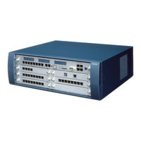
Siemens HiPath 3800 Service Manual (1202 pages)
Brand:
Siemens
| Category:
Telephone
| Size: 21.23 MB
Table of Contents
Table of Contents
3
Figure 8-7 Changing Licenses on an Opticlient Attendant V7.0 as Part of an Upgrade to Hipath
12
Table C-7 Optipoint 400, Optipoint 410, Optipoint 410 S, Optipoint 420, Optipoint 420 S
17
1 Important Information
19
Overview
19
Structure of this Electronic Service Manual
20
Hipath 3000 V6.0, Hipath 5000 V6.0 , Provisional Service Manual
21
Electrical Environment
22
Safety Information
23
Hipath 3000 V6.0, Hipath 5000 V6.0 , Provisional Service Manual
23
Safety Information: Dangers
24
Hipath 3000 V6.0, Hipath 5000 V6.0 , Provisional Service Manual
25
Safety Information: Warnings
26
Hipath 3000 V6.0, Hipath 5000 V6.0 , Provisional Service Manual
27
Safety Information: Cautions
27
General Information
28
Hipath 3000 V6.0, Hipath 5000 V6.0 , Provisional Service Manual
29
Reporting Accidents
30
What to Do in an Emergency
30
Hipath 3000 V6.0, Hipath 5000 V6.0 , Provisional Service Manual
31
Safety Information for Australia (for Australia Only)
31
Privacy and Data Security
32
Information on the Intranet
33
Table 4-1 Table
33
Hipath 3000 V6.0, Hipath 5000 V6.0 , Provisional Service Manual
33
2 System Data
35
Overview
35
Hipath 3000
37
Introduction
37
Design and Dimensions of Hipath 3800
38
Design and Dimensions of the Hipath 3000 Systems
38
Hipath 3000
38
Figure 2-1 Hipath 3800 Dimensions
39
Design and Dimensions of Hipath 3750
40
Design and Dimensions of Hipath 3550
42
Figure 2-3 Hipath 3550 Dimensions
42
Design and Dimensions of Hipath 3350
43
Design and Dimensions of Hipath 3700
44
Figure 2-5 Hipath 3700 Dimensions
44
Design and Dimensions of Hipath 3500
45
Figure 2-6 Hipath 3500 Dimensions
45
Design and Dimensions of Hipath 3300
46
Figure 2-7 Hipath 3300 Dimensions
46
System Environment of the Hipath 3000 Systems
47
Hipath 3800 System Environment
47
Hipath 3750 and Hipath 3700 System Environment
48
Hipath 3550 System Environment
49
Hipath 3350 System Environment
50
Hipath 3500 System Environment
51
Hipath 3300 System Environment
52
Hipath 3300
52
Hipath 5000
53
P31003-H3560-S403
54
System-Specific Capacity Limits for Hipath 3000, Hipath 5000
56
Table 2-7 Hipath 3000/5000 - System-Specific Capacity Limits (Maximum Configuration)
56
System-Specific Capacity Limits for Hipath 3000, Hipath 5000
57
Static Configuration Rules
58
Table 2-8 Technical Data (Resources) of the HG 1500 Boards Defined as Media Gate
58
Dynamic Configuration Rules
60
Gateway Channels (DSP Channels)
60
Table 2-10 Number of Required Gateway Channels (HG 1500 Boards)
60
MOH Channels (G.711, G.723, G.729)
62
IP Networking Channels (PBX Networking Channels)
62
DMC (Direct Media Connection) Channels
63
ISDN Routing/Ppp Channels
63
Table 2-11 HG 1500 - Board-Specific Sum of PPP Channels and Gateway Channels
63
Bandwidth Control for IP Networking Channels (PBX Networking Channels)
63
Fax / Modem Channels
64
Determining the Number of HG 1500 Boards Required
65
Calculation Example 1: 32 IP Networking Connections to Hipath 3750
68
Hipath 3700
68
Sample Calculation
68
Calculation Example 2: 96 IP Workpoint Clients and 16 IP Networking
69
Connections to Hipath 3750, Hipath 3700
69
Calculation Example 3: 200 IP Workpoint Clients and Internet Access to Hi
70
Path 3750, Hipath 3700
70
Calculation Example 4: IP Networking Connections and Voice over
72
PPP (ISDN Routing) to Hipath 3750, Hipath 3700
72
Calculation Example 5: Virtual Private Network VPN
73
Calculation Example 6: Connecting Teleworkers Via VPN
75
Calculation Example 7: Virtual Private Network VPN with Customer
77
Specifications: 1000 Kbps Bandwidth for Data Transfer, Remaining
77
Notes on the Maintenance of Gateway Channels Hipath
79
Technical Specifications for Hipath 3000
80
Interface-To-Interface Ranges
81
Numbering Plan for Hipath 3000/5000
82
Numbering Plan for Hipath
82
Technical Specifications and Compliance to Hipath 3000
83
CE Compliance (Not for U.S.)
83
Compliance with US and Canadian Standards (for U.S. and Canada Only)
83
FCC Compliance
84
FCC Rules, Part 15
84
FCC Rules, Part 68
84
Equipment Attachment Limitations
87
Industry Canada Compliance
87
Ren
87
SAFETY International
88
Environmental Conditions
89
Electrical Operating Conditions
89
Mechanical Operating Conditions
89
Table 3-1 Hipath 3000 - Functional Overview of All Boards Used
91
Table 3-2 Hipath 3000 - Overview of All Boards Models Used
98
3 Boards for Hipath 3000
102
Overview
102
Central Boards
108
Cbcc
108
Table 3-5 CBCC - S Interface Assignment (RJ45 Jacks)
111
Table 3-6 CBCC - V.24 Interface Assignment (SUB-D Plug)
112
Table 3-7 CBCC - LAN Connector Assignment (RJ45 Jack) Via LIM
112
Cbrc
115
Figure 3-2 CBRC Board (S30810-Q2935-Z301)
117
Table 3-12 CBRC - S Interface Assignment (RJ45 Jacks)
118
Table 3-13 CBRC - V.24 Interface Assignment (SUB-D Plug)
119
Table 3-14 CBRC - LAN Connector Assignment (RJ45 Jack) Via LIM
119
Cbcpr
122
Table 3-17 CBCPR - V.24 Interface Assignment (SUB-D Plug)
124
Table 3-18 CBCPR - LAN Connector Assignment (RJ45 Jack)
124
Cbsap
125
Figure 3-4 CBSAP Board (S30810-Q2314-X)
126
Figure 3-5 CBSAP - Front Panel
127
Table 3-19 CBSAP - V.24 Interface Assignment (SUB-D Plug)
128
Table 3-20 CBSAP - LAN Connector Assignment (RJ45 Jack)
128
Cma
129
Figure 3-6 CMA with Spacing Bolts
129
Cms
130
Cr8N
134
Figure 3-8 CR8N (S30810-Q2513-X100)
135
Table 3-22 CR8N - LED Statuses
135
CUC and CUCR
136
CUP and CUPR
137
Dbsap
138
Figure 3-13 DBSAP (S30807-Q6722-X)
138
Figure 3-14 DBSAP on the Backplane of the Expansion Cabinet
139
Imodn
140
Lim
141
Figure 3-15 LIM in Hipath 3750 and Hipath 3700 - Procedure for LAN
142
Figure 3-16 LIM in Hipath 3750 and Hipath 3700 - Adapter Cable
142
Figure 3-17 LIM in Hipath 3750 and Hipath 3700 - Attachment of the Patch Cable
143
Figure 3-18 CBSAP with LIMS Module Plugged in
144
Lims
144
Luna2
146
Figure 3-19 LUNA2 Front Panel
148
Figure 3-20 LUNA2 Slots in the Basic Cabinet (with Outer Panel Mounted)
150
Figure 3-21 LUNA2 Slots in the Expansion Cabinet (with Outer Panel Mounted)
151
Table 3-26 Determining the Number of LUNA2 Modules Required Per Cabinet
152
Figure 3-22 Rear View of the BSG 48/38 Battery Cabinet (S30122-K5950-F300)
153
Figure 3-23 Connections between the BSG 48/38 Battery Cabinet and
154
MMC
155
Table 3-27 Multimedia Card Models and Applications
155
Psup
157
RGMOD (for Selected Countries Only)
158
Upsc-D
162
Figure 3-27 UPSC-D (S30122-K5660-M300)
164
Figure 3-28 UPSC-D (S30122-K5660-M300)
164
Figure 3-29 UPSC-D - Switches and Leds
165
Figure 3-30 UPSC-D - Connectors
166
Upsc-Dr
167
Figure 3-33 UPSC-DR - Switches and Leds
171
Figure 3-34 UPSC-DR - Connectors
172
Upsm
173
Figure 3-35 Front and Rear Views of the UPSM (S30122-K5950-S100)
176
Figure 3-37 Rear View of the BSG 48/38 Battery Cabinet (S30122-K5950-F300)
178
Figure 3-38 Connections between the BSG 48/38 Battery Cabinet and UPSM (Hipath 3750, Hipath 3700)
179
Peripheral Boards
180
Csape
180
Figure 3-40 Hipath 3800 - Board Slots in the Basic Cabinet
182
DIU2U (for U.S. Only)
183
Table 3-33 DIU2U (for U.S. Only) - LED Statuses
185
Diun2
186
Hxgm3
190
Table 3-37 HXGM3 Board Versions
190
Figure 3-45 HXGM3 - Interfaces
192
Hxgs3, Hxgr3
196
Table 3-43 HXGS3/HXGR3 Board Versions
197
Table 3-44 HXGS3/HXGR3 - Extension Modules
197
Figure 3-48 HXGS3 (S30810-Q2943-X)
198
Figure 3-49 HXGR3 (S30810-K2943-Z)
198
Figure 3-50 HXGS3/HXGR3 - Interfaces
199
Table 3-45 HXGS3/HXGR3 - LAN Interface Assignment
200
Figure 3-52 HXGS3 - Securing Clips for Fan Kit
204
Figure 3-53 HXGS3 - Connection of the Fan Kit
204
Ivml8, Ivml24
205
Figure 3-54 IVML8 and IVML24 - Packing Protection Covering
206
Ivmnl, Ivmn8
210
Figure 3-57 IVMNL/IVMN8 - Packing Protection Covering
211
Figure 3-58 IVMNL/IVMN8 - Front Panel (S30122-H7688-X -X100)
212
IVMP8 (Not for U.S.), IVMP8R (Not for U.S)
215
Figure 3-59 IVMP8 and IVMP8R (Not for U.S.) - Packing Protection Covering
216
Figure 3-60 IVMP8, IVMP8R (S30122-Q7379-X100, -K7379-Z100)
217
Ivms8, Ivms8R
220
Figure 3-61 IVMS8 and IVMS8R - Packing Protection Covering
221
Figure 3-62 IVMS8 and IVMS8R (S30122-Q7379-X, -K7379-Z)
222
PBXXX (for Selected Countries Only)
226
Table 3-55 PBXXX (for Selected Countries Only) - Seven-Segment Display
228
Figure 3-65 Hipath 3800 Basic Cabinet - 1X DIUN2 + 1 X PBXXX
229
Figure 3-66 PBXXX (for Selected Countries Only) - Connecting the cas Cable
230
Figure 3-67 PBXXX (for Selected Countries Only) - Adapter-Panel
231
Figure 3-68 Hipath 3800 Basic Cabinet - 1X DIUN2 + 2 X PBXXX
232
Figure 3-69 PBXXX (for Selected Countries Only) - Connecting the cas
233
SLA8N (Not for U.S.), SLA16N, SLA24N
235
Table 3-58 SLA8N (Not for U.S.), SLA16N, SLA24N - LED Statuses
236
Table 3-61 SLA16N, SLA24N - Assignment (SU Xx8, Xx9) (for U.S. Only)
240
SLC16N (Not for U.S.)
242
Figure 3-71 SLC16N (S30810-Q2193-X100) (Not for U.S.)
243
Table 3-62 SLC16N (Not for U.S.) - LED Statuses
243
Table 3-63 SLC16N (Not for U.S.) - Cable Assignment
245
Table 3-65 Hipath 3550 - Maximum Number of Corded Telephones Depending on the
249
Table 3-66 Hipath 3550 - Maximum Number of Corded Telephones Depending on the Number of BS2/2 Base Stations Connected to SLC16N (Not for U.S.)
249
Figure 3-73 Base Station Power Supply Via Two U P0/E Interfaces (Not for U.S.)
252
Figure 3-75 EPSU2 - Indicators and Ports
255
Figure 3-76 EPSU2 - Holes for Mounting on the Wall
258
Figure 3-77 SLCN (S30810-Q2193-X300) - Leds on the Front Panel
259
SLCN (Not for U.S.)
259
Table 3-70 SLCN:LED Statuses
260
Table 3-71 SLCN - SIVAPAC Connector Assignment on the Backplane
261
Table 3-72 SLCN - Connector Panel Assignment with RJ45 Jacks
262
Table 3-73 SLCN - Connector Panel Assignment with SIPAC 1 SU Connectors
264
Figure 3-78 SLMA/SLMA8 - Leds on the Front Panel
266
Slma, Slma8
266
Table 3-74 SLMA/SLMA8 - LED Statuses
267
Table 3-75 SLMA/SLMA8 - SIVAPAC Connector Assignment on the Backplane
268
Table 3-76 SLMA/SLMA8 - Connector Panel Assignment with RJ45 Jacks
270
Table 3-77 SLMA/SLMA8 - Connector Panel Assignment with CHAMP Jack
273
Table 3-78 SLMA, SLMA8 - Connector Panel Assignment with SIPAC 1 SU Connectors (Cable for Ports 1 - 16)
274
Table 3-79 SLMA, SLMA8 - Connector Panel Assignment with SIPAC 1 SU Connectors
274
Table 3-91 SLMA, SLMA8 - Connector Panel Assignment with SIPAC 1 SU Connectors
274
Figure 3-79 SLMA2 (S30810-Q2246-X) (for Selected Countries Only) - Led's
276
SLMA2 (for Selected Countries Only)
276
Table 3-80 SLMA2 (for Selected Countries Only) - LED Statuses
277
Table 3-81 SLMA2 (for Selected Countries Only) - SIVAPAC Connector Assignment on the Backplane
278
Figure 3-80 SLMO2/SLMO8 - Leds on the Front Panel
286
Slmo2, Slmo8
286
Table 3-86 SLMO2 and SLMO8 - LED Statuses
287
Table 3-87 SLMO2/SLMO8 - SIVAPAC Connector Assignment on the Backplane
288
Table 3-88 SLMO2/SLMO8 - Connector Panel Assignment with RJ45 Jacks
290
Table 3-89 SLMO2/SLMO8 - Connector Panel Assignment with CHAMP Jack
293
Table 3-90 SLMO2/SLMO8 - Connector Panel Assignment with SIPAC 1 SU Connectors (Cable for Ports 1 - 16)
294
SLMO8 (Not for U.S.), SLMO24
296
Table 3-92 SLMO8 (Not for U.S.) and SLMO24 - LED Statuses
297
Table 3-93 SLMO8 (Not for U.S.), SLMO24 - Cable 1 Assignment (SU Xx8)
298
Table 3-96 Table
298
Table 3-95 SLMO24 - Assignment (SU Xx8, Xx9) (for U.S. Only)
300
Slu8
302
Slu8R
303
STLS2 (Not for U.S.), STLS4
304
Figure 3-85 Sample Pin Assignments in MW Jacks (Not for U.S.)
307
Figure 3-86 Wiring and Ranges for S Bus Jacks (Not for U.S.)
308
Figure 3-88 S Bus Wiring from STLS4 Port or Optiset E ISDN Adapter
310
Stls4R
311
Table 3-99 STLS4R Contact Assignments
312
Stlsx2, Stlsx4, Stlsx4R
313
Figure 3-91 Pin Assignments in MW Jacks
316
Figure 3-92 Wiring and Ranges for S Bus Jacks
317
Figure 3-93 STMD3 (S30810-Q2217-X10) - Leds on the Front Panel
318
Stmd3
318
Table 3-101 STMD3 - LED Statuses
319
Table 3-102 STMD3 - SIVAPAC Connector Assignment on the Backplane
320
Table 3-103 STMD3 - Connector Panel Assignment with RJ45 Jacks
321
Figure 3-94 STMD8 (S30810-Q2558-X200)
324
Stmd8
324
Figure 3-95 S Trunk Connection (Example for Hipath 3750)
326
Figure 3-96 SNT Connection(Not for U.S.)
326
Figure 3-97 S Networking Options (Not for U.S.) (Examples for Hipath 3750)
328
Figure 3-98 S Bus to the STMD8 over the MDFU or MDFU-E (Not for U.S.)
329
Figure 3-100 S Bus - Example of Jack Assignment (Not for U.S.)
330
Table 3-108 STMD8 - Assignment (Suxx8) (for U.S. Only)
332
Stmi2
334
Table 3-109 STMI2 - Board Variants
334
Figure 3-103 STMI2 - Front Panel
337
Tiel
340
Figure 3-106 E&M Interface Type 1A (Not for U.S.)
346
Figure 3-107 E&M Interface Type 1B or 5 (Not for U.S.)
347
Figure 3-108 E&M Interface Type 2 (Not for U.S)
348
TLA2 (Not for U.S.), TLA4 (Not for U.S.), TLA8 (Not for U.S.)
355
TLA4R (Not for U.S.)
357
Table 3-119 TLA4R (Not for U.S.) Contact Assignments
358
Figure 3-113 TM2LP - Front Panel (S30810-Q2159-XXXX)
359
Tm2Lp
359
Table 3-120 TM2LP - LED Statuses
360
Table 3-121 TM2LP - SIVAPAC Connector Assignment on the Backplane
361
Table 3-122 TM2LP - Connector Panel Assignment with RJ45 Jacks
362
Table 3-124 TM2LP - Connector Panel Assignment with SIPAC 1 SU Connectors
365
TMAMF (for Selected Countries Only)
366
Figure 3-115 Pin Assignments of the TMAMF Diagnostic Cable
367
Table 3-127 TMAMF - Cable Assignment
369
Figure 3-116 TMC16 (for Selected Countries Only) (S30810-Q2485-X) - Front
370
TMC16 (for Selected Countries Only)
370
Table 3-128 TMC16 (for Selected Countries Only) - LED Statuses
371
TMCAS (for Selected Countries Only)
375
Table 3-137 TMDID (for U.S. Only) - LED Statuses
385
TMDID (for U.S. Only)
385
Figure 3-120 TMDID (for U.S. Only) (S30810-Q2452-X) - Front Panel
386
TMDID8 (for U.S. Only)
390
Tmew2
393
Figure 3-122 TMEW2 - Front Panel (S30810-Q2292-X100)
394
Table 3-144 TMEW2 - LED Statuses
395
Table 3-145 TMEW2 - SIVAPAC Connector Assignment on the Backplane
396
Figure 3-123 TMGL4 (for U.S. Only) - Interfaces (S30810-Q2918-X)
397
TMGL4 (for U.S. Only)
397
Figure 3-124 TMGL4R (for U.S. Only) (S30810-K2918-Z)
399
TMGL4R (for U.S. Only)
399
Figure 3-125 TMGL8 (for U.S. Only) (S30810-K2703-Z)
401
TMGL8 (for U.S. Only)
401
Figure 3-126 TML8W (Not for U.S.) (S30817-Q626-Axxx, -Bxxx)
403
TML8W (Not for U.S.)
403
Table 3-150 TML8W (Not for U.S.) - LED Statuses
404
Table 3-151 TML8W (Not for U.S.) - Cable Assignment
405
Figure 3-127 TMQ4 (for U.S. Only) (S30810-Q2917-X)
406
TMQ4 (for U.S. Only)
406
Figure 3-128 TMST1 (for U.S. Only) (S30810-Q2920-X)
408
TMST1 (for U.S. Only)
408
Table 3-153 TMST1 (for U.S. Only) - LED Statuses
409
Figure 3-129 TMST1 Adapter (SIPAC 1 SU - MW8 (RJ48C)) C39228-A7195
410
Table 3-154 TMST1 Adapter (for U.S. Only) - Cable Assignment
410
TMS2 (Not for U.S.)
411
Figure 3-131 S 2M Trunk Connection
414
Figure 3-133 S 2M - NT Connection (Not for U.S.)
415
Figure 3-134 S 2M Connection to Deutsche Telekom NT (for Germany Only)
416
Figure 3-135 S
417
Figure 3-136 TST1 (for U.S. Only) (S30810-Q2919-X/S30810-K2919-Z)
418
TST1 (for U.S. Only)
418
TS2 (Not for U.S.), TS2R (Not for U.S.)
420
Figure 3-137 TS2 (Not for U.S.) - Interfaces (S30810-Q2913-X100, -X300)
421
Figure 3-138 TS2R (Not for U.S.) - Interfaces (S30810-K2913-Z100, -Z300)
421
Figure 3-139 S
423
Figure 3-140 S 2M - NT Connections for Spain and Portugal
424
4SLA (Not for U.S.), 8SLA, 16SLA (Not for U.S.)
425
8Slar
428
Figure 3-143 8SLAR Interfaces (S30810-K2925-Z)
428
Table 3-162 8SLAR Contact Assignments
428
Options
430
Alum4
430
Figure 3-144 ALUM4 - Function
430
Figure 3-145 ALUM4 - Interfaces (S30817-Q935-A)
431
Table 3-163 ALUM4 - Interface Assignments (Not for U.S.)
431
Amom
434
ANI4 (for Selected Countries Only)
436
Figure 3-148 ANI4 (for Selected Countries Only) - Interfaces
436
Table 3-167 ANI4 (for Selected Countries Only) - Contact Assignments
438
Figure 3-149 ANI4 (for Selected Countries Only) - Installation Steps
439
ANI4R (for Selected Countries Only)
440
Figure 3-150 ANI4R (for Selected Countries Only) (S30807-Q6917-Z103)
440
Announcement and Music Modules
442
Evm
445
Figure 3-153 EVM (S30807-Q6945-X) - Interfaces
446
EXMNA (for U.S. Only)
447
Figure 3-154 EXMNA (for U.S. Only) (S30807-Q6923-X)
447
Table 3-170 EXMNA (for U.S. Only) - Contact Assignments
448
Figure 3-156 GEE8 (Not for U.S.) (S30817-Q664-XXXX)
449
GEE8 (Not for U.S)
449
Figure 3-157 GEE12, GEE16, GEE50 (Not for U.S.) - Interfaces
450
GEE12 (nor for U.S.), GEE16 (Not for U.S.), GEE50 (Not for U.S.)
450
Table 3-171 GEE12/GEE16/GEE50 (Not for U.S.) Modules
450
Table 3-172 GEE12, GEE16, GEE50 (Not for U.S.) - Contact Assignments
451
Figure 3-158 HOPE (for U.S. Only) (S30122-Q7078-X; S30122-Q7079-X)
452
HOPE (for U.S. Only)
452
Figure 3-159 OPAL (C39195-A7001-B130)
454
OPAL and OPALR
454
Figure 3-160 OPALR (C39195-A7001-B142)
455
PFT1 (Not for U.S.), PFT4 (Not for U.S.)
456
Figure 3-162 Installation Location of PFT1 and PFT4 (MDFU/MDFU-E)
457
Real
459
Figure 3-164 Installation Location of the REAL Board
460
Reals
463
Figure 3-166 REALS (S30807-Q6629-X)
464
Figure 3-167 REALS Slots in the Basic Cabinet (with Outer Panel Mounted)
465
Table 3-174 REALS - SIVAPAC Connector Assignment on the Backplane
467
STBG4 (for France Only)
468
Strb, Strbr
469
Table 3-176 STRB Contact Assignments
472
Figure 3-172 V24/1 (Not for U.S.) (S30807-Q6916-X100)
474
Figure 3-173 Hipath 3550 and Hipath 3350 - V.24 Connections
474
V24/1 (Not for U.S.)
474
V.24 Adapter
476
V.24 Cable
477
4 Installing Hipath 3000
479
Overview
479
Installing Hipath 3800
482
Installation Procedure
482
Installing Hipath 3800 (Standalone)
483
Selecting the Installation Site
483
For U.S. Only: AC Outlet
484
Unpacking the Components
485
Overview
486
Setting up the System Cabinets
486
Figure 4-1 Hipath 3800 - Setting up the Basic Cabinet
487
Setting up a Single Cabinet
487
Stacking Two Cabinets
488
Figure 4-2 Hipath 3800 - Positioning the Cabinet Feet
489
Figure 4-3 Hipath 3800 - Installing a Stacked Two-Cabinet System
490
Setting up a Two-Cabinet System Side by Side
491
Grounding the System
493
Not for U.S.: Grounding the System
493
For U.S. Only: Grounding the System
496
Figure 4-8 Hipath 3800 - Earth Ground Connection (for U.S. Only)
497
Checking the Grounding
498
Installing Hipath 3800 (19-Inch Cabinet)
499
Selecting the Installation Site
499
Figure 4-9 Hipath 3800 - System Cabinet with Plastic Cover
500
Figure 4-10 Hipath 3800 - Installation Examples in the 19-Inch Cabinet
501
For U.S. Only: AC Outlet
502
Table 4-3 Electrical Connection Values (USA Only)
502
Unpacking the Components
502
Mounting a System Cabinet Using Support and Angle Brackets
503
Mounting System Cabinets in the 19-Inch Cabinet
503
Figure 4-11 Hipath 3800 - Removing Cabinet Feet
504
Figure 4-12 Hipath 3800 - Installing System Cabinets in 19-Inch Cabinet
505
Grounding the System
506
Checking the Grounding
508
Board Slots in the Basic and Expansion Cabinet
509
Installing Boards (Configuration Notes)
509
Figure 4-14 Hipath 3800 - Board Slots in the Basic Cabinet
510
Figure 4-15 Hipath 3800 - Board Slots in the Expansion Cabinet
511
Inserting or Removing Boards
512
Figure 4-16 Hipath 3800 - Removing/Inserting the Board Using the Board
513
Figure 4-17 Installing the Board Shielding Cover
513
Figure 4-19 Hipath 3800 - Installing the LUNA2 Power Supply Unit
515
Figure 4-20 Hipath 3800 - Slots for LUNA2 and REALS in the Basic Cabinet
516
Figure 4-21 Hipath 3800 - Slots for LUNA2 in the Expansion Cabinet
516
Figure 4-22 Hipath 3800 - Installing the REALS Board
517
Mounting Connector Panels (if Required)
518
Installing the SIVAPAC-SIPAC Board Adapter
520
Figure 4-24 Installing the SIVAPAC-SIPAC Board Adapter
521
Figure 4-26 Hipath 3800 - Initialization of Subscriber Line Circuits and Ports
523
Initializing the Boards
523
Distribution of the PCM Highway
524
Figure 4-27 Hipath 3800 - PCM Highways in the Basic Cabinet
524
Figure 4-28 Hipath 3800 - PCM Highways in the Expansion Cabinet
525
Static Traffic Capacity
528
Connecting the Cable to the Backplane
529
Backplane of the Basic Cabinet
530
Figure 4-29 Hipath 3800 - Backplane (S30804-Q5392-X) of the Basic Cabinet
530
Figure 4-30 Hipath 3800 - Connectors and Jacks on the Backplane of the
531
Expansion Cabinet Backplane
533
Figure 4-31 Hipath 3800 - Expansion Cabinet Backplane (S30804-Q5393-X)
533
Figure 4-32 Hipath 3800 - Connectors and Jacks on the Backplane of the
534
Connecting Cables between the Basic and Expansion Cabinet
535
Connecting Peripherals to the SIVAPAC Connector on the Backplane
536
Figure 4-33 Hipath 3800 - Backplane of the Basic Cabinet with Mounted Filler
538
Connecting Peripherals to the Connector Panels with RJ45 Jacks
539
Figure 4-34 Hipath 3800 - Connector Panels with RJ45 Jacks
539
CHAMP Jack
541
Figure 4-35 Hipath 3800 - Connector Panel with CHAMP Jack (for U.S. Only)
541
For U.S. Only: Connecting Peripherals to the Connector Panels with
541
Connecting Peripherals to the Connector Panels with SIPAC 1 SU
542
Connectors
542
Figure 4-36 Hipath 3800 - Connector Panel with Two SIPAC 1 SU Connectors
542
Using an External Main Distribution Frame or External Patch Panel
544
Using an External Main Distribution Frame MDFU-E S30805-U5283-X
545
Laying the Line Network and Jumpers on the MDFU-E
546
Mounting the Main Distribution Frame (MDFU-E)
546
Figure 4-38 Assignment (Numbering) of the Splitting/Jumper Strips
547
Figure 4-40 Patch Panel S30807-K6143-X
550
Inserting the External Patch Panel S30807K6143-X
550
Figure 4-41 Installing the External Patch Panel in the 19-Inch Cabinet
551
Installing the Patch Panel in a 19-Inch Cabinet
551
Connecting the Line Network to the External Patch Panel
552
Figure 4-42 Layout of the Patch Panel S30807-K6143-X for Different
552
Figure 4-44 S
554
Inserting External S
554
Patch Panel C39104-Z7001-B3
554
Figure 4-45 Installing the External S Patch Panel in the 19-Inch Cabinet
555
Installing the S
555
Patch Panel in the 19-Inch Cabinet
555
Connecting Lines to the External S Patch Panel
556
For U.S. Only: Connecting Network Facilities
558
Loading the System Software and Installing Subboards on the CBSAP
559
Connecting Workpoint Clients
560
Making Trunk and Networking Connections
560
Performing a Visual Inspection
561
Table 4-9 Visual Inspection Procedure
561
Installing Hipath 3750, Hipath 3700
563
Installation Prerequisites
563
Installation Procedure
564
Installing Hipath 3750
564
Selecting the Installation Site
567
For U.S. Only: AC Outlet
568
Unpacking the Components
569
Install MDFU or MDFU-E (Not for USA)
570
Overview
571
Setting up the System Cabinets
571
Figure 4-49 Hipath 3750 - Removing the Front and Rear Covers
572
Removing the Cabinet Covers
572
Mounting a One-Cabinet System on the Wall (for U.S. Only)
573
Setting up a Single Cabinet
573
Figure 4-51 Hipath 3750 Mounting a One-Cabinet System on the Wall
574
Stacking Two Cabinets
575
Figure 4-53 Hipath 3750 - Mounting the Stabilizer Feet
577
Figure 4-54 Hipath 3750 - Wall-Mount Kit (for U.S. Only)
578
For U.S. Only: Mounting Two Cabinets Stacked on the Wall
578
Figure 4-55 Hipath 3750 Wall Mounting for a Stacked Two-Cabinet System
579
Figure 4-56 Hipath 3750 - Installing a Two-Cabinet System (Side by Side)
581
Setting up a Two-Cabinet System Side by Side
581
Setting up a Stacked Three-Cabinet System
582
Figure 4-57 Hipath 3750 - Installing a Three-Cabinet System (Stacked)
583
Figure 4-58 Hipath 3750 Seismic Anchors (for U.S. Only)
584
For U.S. Only: Installing the Seismic Anchors
584
Figure 4-59 Hipath 3750 Seismic Anchoring for Multiple Cabinets
585
Grounding the System
586
Not for U.S.: Grounding the System
586
For U.S. Only: Grounding the System
589
Figure 4-63 Hipath 3750 - Grounding Connector for Basic Cabinet
590
Checking the Grounding
591
Backplanes on the "8-Slot" Cabinets
592
Connecting the Cable to the Backplane
592
Figure 4-64 Hipath 3750 - Backplane on the "8-Slot" Basic Cabinet
592
Figure 4-65 Hipath 3750 - Backplane on the "8-Slot" Expansion Cabinets
593
Table 4-12 Jack Assignment on the "8-Slot" Backplane
593
Figure 4-66 Two-Cabinet "8-Slot" System - Connection Cables between
595
Figure 4-67 Three-Cabinet "8-Slot" System - Connection Cables between BC
596
Connection between the MDFU or MDFU-E and Backplane
597
Figure 4-68 S 2M Adapter (SIPAC 1 SU - MW8 (RJ48C)) C39228-A7195-A12
599
Laying the Line Network and Setting Jumpers on the MDFU or
602
Mdfu-E
605
For U.S. Only: Connecting Network Facilities
606
Installing Hipath 3700 (19-Inch Cabinet)
607
For U.S. Only: AC Outlet
608
Selecting the Installation Site
608
Table 4-14 Electrical Connection Values (for U.S. Only)
608
Unpacking the Components
608
Mounting the System Cabinet in the 19-Inch Cabinet
609
Removing the Cabinet Covers
609
Mounting the System Cabinet with Angle Brackets
611
Figure 4-74 Hipath 3700 - Installation in the 19-Inch Cabinet
612
Figure 4-75 Hipath 3700 - Mounting the Patch Panel
613
Mounting the Patch Panel in the 19-Inch Cabinet
613
Grounding the System
614
Checking the Grounding
616
Backplanes on the "8-Slot" Cabinets
617
Connecting the Cable to the Backplane
617
Figure 4-77 Hipath 3700 - Backplane on the "8-Slot" Basic Cabinet
617
Cabinet
618
Figure 4-78 Hipath 3700 - Backplane on the "8-Slot" Expansion Cabinets
618
Table 4-15 Jack Assignment on the "8-Slot" Backplane
618
Figure 4-80 Three-Cabinet "8-Slot" System - Connection Cables between
621
Figure 4-81 Patch Panel S30807-K6143-X
624
Figure 4-83 S
626
Figure 4-84 Laying Wire Pairs at the S Patch Panel
627
Figure 4-85 Stripping the Open-End Cable for the S Patch Panel
628
Figure 4-86 S 2M Adapter (SIPAC 1 SU - MW8 (RJ48C)) C39228-A7195-A12
629
Connecting the Line Network to the Patch Panel
630
Figure 4-87 Layout of the Patch Panel S30807-K6143-X for Different
630
Loading the System Software and Installing Subboards on the CBCPR
631
Configuration Notes
632
Figure 4-88 Slot Numbers and Widths in "8-Slot" BC, EC1, and EC2
633
Figure 4-91 PCM Segments for a Two-Cabinet System
638
Figure 4-92 PCM Segments for a Three-Cabinet System
638
Table 4-17 Hipath 3750 and Hipath 3700 - Static Traffic Capacity
639
Figure 4-93 Locking and Unlocking Boards
640
Inserting or Removing Boards
640
Connecting Workpoint Clients
641
Making Trunk Connections
641
Performing a Visual Inspection
642
Installing Hipath 3550, Hipath 3350, Hipath 3500, and Hipath 3300
643
Installation Prerequisites
643
Installation Procedure
644
Installing Hipath 3550 and Hipath 3350
645
Selecting the Installation Site
645
For U.S. Only: AC Outlet
647
Not for U.S.: Mounting the Main Distribution Frame (Hipath 3550 Only)
648
Unpacking the Components
648
Removing the System Housing Cover
650
Attaching the System to the Wall
652
Grounding the System and the Main Distribution Frame
653
Installing the Boards
655
Figure 4-99 Layout of CABLU S30269-Z41-A30 (Length = 3 M)
656
Laying the Line Network and Connection Cables
656
Attaching Ferrite
659
Configuration Notes
661
Figure 4-103 Hipath 3550 - Wall Housing System Overview
661
Table 4-21 Hipath 3550 and Hipath 3350 - Static Traffic Capacity
664
Connecting Workpoint Clients
665
Making Trunk Connections
665
Performing a Visual Inspection
665
Installation Versions
666
Installing Hipath 3500 and Hipath 3300 (19-Inch Housing)
666
For U.S. Only: AC Outlet
667
Selecting the Installation Site
667
Unpacking the Components
668
Figure 4-108 Hipath 3500 and Hipath 3300 - Wall Installation (for U.S.)
669
Not for U.S.: Attaching a Hipath 3500 and Hipath 3300 to the Wall
669
Installing a Hipath 3500 or Hipath 3300 in a Cabinet
670
Figure 4-109 Hipath 3500 and Hipath 3300 - Mounting the 19-Inch Cabinet
671
Grounding the System
672
Figure 4-110 Hipath 3500 and Hipath 3300 - Grounding
673
Installing the Boards
673
Connecting Cables and the Line Network
674
Figure 4-111 Hipath 3500 and Hipath 3300 - Connection Cable to ECR
674
Configuration Notes
675
Figure 4-112 Hipath 3500 - Slot Levels in the 19-Inch Housing
675
Figure 4-113 Hipath 3300 - Slot Levels in the 19-Inch Housing
676
Connecting Workpoint Clients
678
Making Trunk Connections
678
Performing a Visual Inspection
678
5 Starting up Hipath 3000
679
Overview
679
Starting up Hipath 3800
679
Startup Procedure
680
Table 5-1 Hipath 3800 - Startup Procedure
680
Supplying the System with Power
681
Table 5-2 RUN LED - LED Status Meaning
681
Assigning Station Numbers
682
Carrying out a System Reload
684
Table 5-3 Entering the Country Code and Selecting the Password Type
686
Not for U.S.: Entering the System Number
687
Customer-Specific Programming
688
Table 5-5 Hipath 3750 and Hipath 3700 - Startup Procedure
689
Supplying the System with Power
690
Table 5-6 RUN LED - LED Status Meaning
690
Assigning Station Numbers
691
Carrying out a System Reload
693
Carrying out the Country Initialization and Selecting the Password Type
693
Not for U.S.: Entering the System Number
695
Customer-Specific Programming
696
Performing a System Check
696
Starting up Hipath 3750 and Hipath 3700
696
Startup Procedure
697
Table 5-9 Startup Procedure
697
Supplying the System with Power
698
Table 5-10 RUN LED - LED Status Meaning
698
Assigning Station Numbers
699
Carrying out a System Reload
701
Not for U.S.: Entering the System Number
703
Customer-Specific Programming
704
Overview
705
6 Hipath 5000 Startup and Administration
705
Introduction
707
Software Structure
710
Table 6-1 Feature Server Components
712
Notes on Open Numbering in a Hipath 3000/5000 Network
713
Installation Requirements
714
Prerequisites for a Single-PC Solution
715
Hipath 5000
715
Preparing for Installation
717
Integrating the Hipath 5000 Server in the Customer LAN
718
Hipath 5000 Installing Standard Components
719
Overview
719
Table 6-6 Software Components and Master Setup Tools
719
Licensing
720
Starting the Installation
721
Installing Hipath Comscendo Service
726
Checking the Installation of the Hipath Comscendo Service
734
Installing Hipath Fault Management
735
Installing the TAPI Service Provider
739
Installing the Hipath Inventory Server Separately
740
Verifying Installation
745
Verifying the Start and Function of Hipath 5000 Services
745
Checking Entries in the Event Viewer
746
Modifying Hipath 5000 Components (Retro-Fitting, Updating, Deleting)
747
Version-Wide Upgrading of a Hipath 5000 Installation
748
Performing Licensing
750
Optimizing Operating System Settings
751
Perform Hipath 5000 Basic Configuration
753
Configuring Hipath 5000 with Hipath Comscendo Service
754
Reloading the Hipath Comscendo Service (if Required)
755
Configuring Hipath 5000 RSM as a Central Administration Unit in an
756
Creating a Central Customer Database for IP Networking
756
IP Network
756
Adding Individual Nodes for IP Networking
758
Hipath Manager PCM
760
Getaccount
761
Parameters for Call Data Export
761
Table 6-8 Getaccount - Data Record Structure
763
Connecting an Uninterruptible Power Supply to Hipath 5000
766
Figure 6-4 P 500 UPS - Front and Rear Panel
766
Table 6-9 P 500 UPS - Meaning of Displays, Switches and Jacks
767
7 Starting Hipath 3000 as a Gateway
769
Overview
769
Introduction
769
Starting Hipath 3800 as a Gateway
770
Prerequisites
770
Procedure for Installation and Startup
770
Starting Hipath 3700 as a Gateway
772
Starting Hipath 3500 as a Gateway
774
Starting Hipath 3300 as a Gateway
776
Introduction
779
Licensing for Hipath 3000 V6.0, Hipath 5000 V6.0
782
Products and Components Subject to Mandatory Licensing
782
Grace Period
784
License Failure Period
784
Performing Licensing
785
Licensing Scenarios
790
Hipath 3000 as a Standalone System
790
Networked Hipath 3000 Systems Without Hipath 5000 RSM
791
Networked Hipath 3000 Systems with Hipath 5000 RSM
792
Upgrading to Hipath 3000 V6.0, Hipath 5000 V6.0
795
Hipath 5000 RSM
798
Removing a Standalone System from a Network with Hipath 5000 RSM
800
Replacing License-Sensitive Hardware (Changing the MAC Address)
801
Licensing Opticlient Attendant
804
Figure 8-3 Procedure for Licensing Opticlient Attendant V7.0 on Hipath
804
Opticlient Attendant V7.0 Connected to Hipath 3000 V6.0
804
Opticlient Attendant V7.0 Connected to Hipath 3000 < V5.0
806
Figure 8-5 Licensing Procedure When Upgrading Opticlient Attendant V6.0 -> V7.0 on Hipath
808
Upgrading Opticlient Attendant V6.0 -> V7.0 as Part of an Upgrade to Hipath
808
Upgrade Opticlient Attendant V6.0 -> V7.0 on Hipath 3000 < V5.0
810
Changing Licenses on an Opticlient Attendant V7.0 as Part of an Upgrade to Hipath 3000 V5.0
812
Protection against License Manipulation
814
9 Expanding and Upgrading Hipath 3000
815
Overview
815
Expanding Hipath 3000
815
Replacing Peripheral Boards for Hipath 3800
816
Table 9-1 Startup Rules for Inserting and Removing Boards
816
Replacing Peripheral Boards for Hipath 3750 and Hipath 3700
818
Table 9-2 Startup Rules for Inserting and Removing Boards
818
P31003-H3560-S403-54-7620
819
Connecting a Printer
820
ECR with Hipath 3700, Hipath 3500, Hipath 3300 (Not for U.S. and Canada)
822
ECR Control, Display, and Connecting Elements
823
Figure 9-2 ECR Front Panel (155 X 440 X 380 MM)
823
Figure 9-3 ECR Rear Panel with Connecting Elements
824
Components
826
Installation Options
826
Expansion Cabinet Rack ECR with Batteries
827
Figure 9-5 ECR with Built-In Batteries
828
Installing Batteries
829
Expansion Cabinet Rack ECR with Batteries and EPSU2-R
832
Figure 9-7 ECR with Built-In EPSU2-R
834
Connecting a Fan (if Needed)
835
Figure 9-8 Connecting the Fan to the EPSU2-R
836
Figure 9-9 Placement of the Fan in the ECR
837
Connecting Special Equipment
838
Entrance Telephones
838
Figure 9-10 Connection Options for Entrance Telephones
838
Figure 9-11 Direct Connection of Entrance Telephones
838
Information on Third-Party Entrance Telephones
839
Connecting Speakers
841
Figure 9-14 Connecting Speakers to an Analog Trunk Port
842
Upgrading Hipath 3000 to V6.0
843
Hardware Upgrade
843
Software Upgrade
845
Figure 9-17 Flowchart for CDB Conversion from V4.0 -> V5.0 (Part 2 of 4)
847
Figure 9-18 Flowchart for CDB Conversion from V4.0 -> V5.0 (Part 3 of 4)
848
Converting the Customer Database When Changing a System
850
Converting the Customer Database from Hipath 3750/Hipath 3700 to
850
Hipath 3800
850
10 Workpoint Clients
853
Overview
853
Optipoint 500
858
Optipoint 500 Entry
858
Optipoint 500 Telephones
858
Optipoint 500 Economy (Not for U.S.)
859
Figure 10-3 Optipoint 500 Basic - Standard Key Assignment (Default)
860
Optipoint 500 Basic
860
Optipoint 500 Standard, Optipoint 500 Standard SL (for U.S. Only)
861
Figure 10-4 Optipoint 500 Standard - Standard Key Assignment (Default)
862
Optipoint 500 Advance
863
Figure 10-5 Optipoint 500 Advance - Standard Key Assignment (Default)
864
Connection Requirements for Hipath 3000
865
Connection
866
Connections on the Bottom of the Telephone
867
Figure 10-6 Optipoint 500 Connection Options
867
USB 1.1 Interface
868
Figure 10-7 Optipoint Key Module
869
Optipoint 500 Add-On Devices
869
Optipoint Key Module
869
Figure 10-8 Optipoint BLF
870
Optipoint BLF
870
Figure 10-9 Optipoint Application Module
871
Optipoint Application Module (V5.0 SMR-06 and Later)
871
Possible Add-On Device Configurations
872
Figure 10-10 Optipoint 500 Option Bays
873
Optipoint 500 Adapters
873
Figure 10-11 Optipoint Analog Adapter
874
Optipoint Analog Adapter
874
Optipoint ISDN Adapter
875
Optipoint Phone Adapter
876
Figure 10-14 Example of a Host-Client Configuration
877
Optipoint Acoustic Adapter
878
Table 10-2 Floating Contacts on the Optipoint Acoustic Adapter
880
Optipoint Recorder Adapter
881
Possible Optipoint Adapter Configurations
882
Comparison of Optiset E Adapters and Optipoint 500 Adapters
883
Table 10-3 Comparison of Optiset E and Optipoint 500 Adapters
883
Information on Supplying Power to Optipoint 500 Add-On Devices and Optipoint 500 Adapters
884
And Adapters
885
Maximum Configuration for U P0/E Workpoint Clients, Add-On Devices
885
Optipoint 410 / Optipoint 410 S and Optipoint 420 / Optipoint 420 S
888
IP Telephony (Voice over IP)
890
Optipoint 410 and Optipoint 410 S Telephones
892
Optipoint 410 Entry, Optipoint 410 Entry S
892
Figure 10-18 Optipoint 410 Entry, Optipoint 410 Entry S - Standard Key
893
Optipoint 410 Economy, Optipoint 410 Economy S
894
Figure 10-19 Optipoint 410 Economy, Optipoint 410 Economy S - Standard
895
Optipoint 410 Economy Plus, Optipoint 410 Economy Plus S
896
Figure 10-20 Optipoint 410 Economy Plus, Optipoint 410 Economy Plus S - Standard
897
Optipoint 410 Standard, Optipoint 410 Standard S
898
Figure 10-21 Optipoint 410 Standard, Optipoint 410 Standard S - Standard Key
899
Optipoint 410 Advance, Optipoint 410 Advance S
900
Figure 10-22 Optipoint 410 Advance, Optipoint 410 Advance S - Standard Key
901
Optipoint 420 and Optipoint 420 S Telephones
902
Optipoint 420 Economy, Optipoint 420 Economy S
902
Figure 10-23 Optipoint 420 Economy, Optipoint 420 Economy S - Standard
903
Optipoint 420 Economy Plus, Optipoint 420 Economy Plus S
904
Figure 10-24 Optipoint 420 Economy Plus, Optipoint 420 Economy Plus S
905
Optipoint 420 Standard, Optipoint 420 Standard S
906
Figure 10-25 Optipoint 420 Standard, Optipoint 420 Standard S - Standard Key
907
Optipoint 420 Advance, Optipoint 420 Advance S
908
Figure 10-26 Optipoint 420 Advance, Optipoint 420 Advance S - Standard Key
909
Connection and Startup
910
Connections on the Bottom of the Telephone
911
Add-On Devices
913
Figure 10-28 Optipoint Self Labeling Key Module
913
Optipoint 410 / Optipoint 410 S and Optipoint 420 / Optipoint 420 S
913
Optipoint Self Labeling Key Module
913
Figure 10-29 Optipoint 410 Display Module
914
Optipoint 410 Display Module
914
Possible Configurations for the Add-On Devices
916
Use of Optipoint 500 Adapters
917
Optipoint 600 Office
919
Table 10-8 Comparison of Optipoint 600 Office and Optiset E Memory
920
Optilog 4Me
921
Figure 10-31 Optilog 4Me
921
Optiset E Privacy Module
922
Optipoint Accessories
923
Local Power Supply for Optiset E, Optipoint 500 and Optipoint
923
Figure 10-33 Example of a Corded and a Cordless Headset
926
Headsets
926
Opticlient 130 V5.0
929
Hipath AP 1120
930
Attendant Console Versions
931
Figure 10-35 Optipoint 500 Standard - Standard Key Assignment (Default)
931
Optipoint Attendant
931
Opticlient Attendant
932
Mobile Telephones for Hipath Cordless Office
937
Figure 10-36 Gigaset S1 Professional
937
Gigaset S1 Professional
937
Figure 10-37 Gigaset SL1 Professional
938
Gigaset SL1 Professional
938
Figure 10-38 Gigaset M1 Professional
939
Gigaset M1 Professional
939
Gigaset Active M
940
Gigaset Active EX
941
Logging Mobile Telephones on to the System
943
Opening the Hipath 3000 Login Window
943
Logging on the Mobile Telephone
944
Checking the Login Status of the Mobile Telephones
945
Replacing, Locking, and Logging off a Mobile Telephone
945
Analog Telephones for Hipath 3000
946
ISDN Terminals for Hipath 3000
947
11 Hipath Cordless Office
949
Overview
949
Introduction
950
System Configuration
951
Technical Data for Base Stations
952
Figure 11-2 BS3/1 (BS3/S) and BS3/3 in the Outdoor Cover S30122-X7469-X
953
Power-Related Capacity Limits
954
Multi-SLC and System-Wide Networking
958
Figure 11-4 Incorrect DECT Configuration of Networked Hipath 3000 Systems
960
Roaming
960
12 Service
963
Overview
963
Service and Maintenance Tasks
965
Automatic Customer Data Backup
965
Backing up the Customer Database (CDB Backup)
965
Customer Data Backup Without Hipath Software Manager
965
Manual Customer Data Backup with Hipath 3000
967
CDB Treatment When Replacing Central Hipath 3000 Hardware
968
Customer Data Backup with Hipath Software Manager
968
Effects of Hardware Changes on Customer Data
970
Inserting and Removing Hipath 3000 Boards
970
Table 12-1 Startup Rules for Inserting and Removing Boards
970
Exchanging Workpoint Clients
972
Hipath Software Manager
973
Relocate/Transfer Application Processor Software (APS)
973
Transferring an APS of Hipath 3000 by Replacing the MMC
973
APS Transfer
974
Manager
978
Upgrading Hipath 3000
979
Determining System Information and Installed Software Components
980
Backing up System Components (Backup Manager)
981
Hipath User Management (Not yet Released)
983
Guided Maintenance
985
Central Control Boards
985
Diagnosis Options
985
Recording Hipath 3000 Board Status
985
Table 12-2 RUN LED - LED Status Meaning
985
Peripheral Boards
986
Power Supplies
986
Recording Hipath 3000 Trunk Status
988
Recording Station Status
989
Recording the Status of the Hipath 3000 V.24 Interfaces
990
Trace Options for Hipath 3000
991
Hipath Manager PCM Trace Monitor Applications
992
Hipath Manager PCM Trace Monitor for Hipath 5000
992
Figure 12-1 Trace Monitor
993
Starting and Exiting the Trace Monitor
993
Figure 12-2 the Screen Layout of the Trace Monitor
994
The Screen Layout of the Trace Monitor
994
Table 12-5 Trace Monitor Menu Functions
995
General Functions
996
Exporting Trace Windows
997
Eventlog for Hipath 3000
999
Table 12-6 Terminal Test
999
Testing Telephones
999
Event Viewer for Hipath 5000 (Eventlog)
1000
Figure 12-3 Hipath 5000 State Viewer
1002
Hipath 5000State Viewer
1002
Hipath Fault Management
1006
Analysis Using Customer License Agent (CLA)
1007
Analysis Using Customer License Manager (CLM)
1007
Licensing Analysis
1007
Manager
1008
Hipath 3000 Error Messages (Entries in the Eventlog for Hipath 3000)
1010
Table 12-7 Hipath 3000 Class B Error Messages
1013
Hipath 5000 Error Messages (Event Viewer Entries for Hipath 5000)
1019
Table 12-8 Event Viewer Entries for the Hipath 5000 Server
1020
Correcting Errors
1032
Automatic Error Correction
1032
Manual Error Correction Without Hipath 3000 Manager E
1032
Manual Error Correction with Hipath 3000 Manager E
1033
Remote Service
1034
Hipath 3000 Connection Options
1035
Hipath 5000 Connection Options
1036
Remote Administration of Hipath 3000 with Hipath 3000 Manager E
1036
Remote System Administration
1036
DTMF Remote Administration of Hipath 3000
1037
Remote Correction of System Software (APS)
1037
Remote Error Signaling
1038
Controlled Release of a Remote Connection
1039
Remote Administration and Access Using PPP
1039
Remote Administration of Plus Products
1039
Remote System Administration
1039
Remote Error Signaling Using SNMP
1040
Security Features
1041
Access Security
1041
Logon with User Name and Password
1041
Pre-Determined User Groups and Their Access Rights
1044
Table 12-10 Fixed Password: Fixed User Groups and Their Access Rights
1045
Table 13-1 Table
1045
System Access Options
1046
Customer Data Security
1047
Automatic Logging of Administration Procedures
1048
Format Identification and Command Entry
1048
Logging
1048
Issuing and Saving Log Data
1051
13 IP Fundamentals
1053
Overview
1053
IP Network Requirements
1054
General Introduction
1054
Protocol
1054
Standards Supported
1055
Qos - Quality of Service
1056
Network Analysis
1058
A System Programming Codes (Expert Mode Codes)
1059
Table A-2 Expert Mode Code Groups
1060
Table A-3 Expert Mode Codes
1061
B Codes for Activating/Deactivating Features
1091
Table B-1 Codes for Activating/Deactivating Features
1094
CIP Protocols and Port Numbers Used with Hipath 3000/5000 V6.0
1119
Opticlient 130 V5.0
1119
C.4 Hipath FM Managed Systems
1125
Table C-5 HG 1500 - IP Protocols and Port Numbers Used
1127
C.6 Opticlient 130 V5.0
1129
C.8 Hipath AP 1120
1134
Middleware for Call Control
1135
D Identifying System Power Requirements
1137
Hipath 3800 Board Power Requirement
1138
Table D-1 Nominal Output of the Hipath 3800 Power Supply Unit
1138
Table D-2 Hipath 3800 Board Power Requirement
1138
Hipath 3750 and Hipath 3700 Board Power Requirement
1140
Table D-4 Hipath 3750 and Hipath 3700 Board Power Requirement
1140
Hipath 3550 Board Power Requirement
1142
Table D-5 Nominal Output of the Hipath 3550 Power Supply Units
1142
Table D-6 Hipath 3550 Board Power Requirement
1142
Hipath 3350 Board Power Requirement
1144
Table D-7 Nominal Output of the Hipath 3350 Power Supply Units
1144
Table D-8 Hipath 3350 Board Power Requirement
1144
Hipath 3500 Board Power Requirement
1146
Table D-10 Hipath 3500 Board Power Requirement
1146
Table D-9 Nominal Output of the Hipath 3500 Power Supply Units
1146
Hipath 3300 Board Power Requirement
1147
Table D-12 Hipath 3300 Board Power Requirement
1147
Workpoint Clients, Key Modules and Adapter Power Requirements
1148
Table D-13 Workpoint Clients, Key Modules and Adapter Power Requirements
1148
Checking Whether the Output of a Power Supply Unit Is Sufficient
1151
Identifying the Primary System Power Requirement
1154
Advertisement
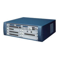
Siemens HiPath 3800 Service Documentation (1302 pages)
Brand:
Siemens
| Category:
Conference System
| Size: 17.35 MB
Table of Contents
Table of Contents
3
1 Introduction and Important Notes
21
Hipath 3000/5000 V9, Service Documentation
21
About this Documentation
22
Documentation and Target Groups
22
Hipath 3000/5000 V9 , Service Documentation
23
Manual Structure
24
Hipath 3000/5000 V9 , Service Documentation
25
Notational Conventions
26
Safety Information and Warnings
27
Hipath 3000/5000 V9 , Service Documentation
27
Warning Sign: DANGER
28
Hipath 3000/5000 V9 , Service Documentation
29
Warning Sign: WARNING
29
Hipath 3000/5000 V9 , Service Documentation
31
Warning Sign: CAUTION
31
Notes
32
Safety Information for Australia (for Australia Only)
32
Safety Information for Brazil (for Brazil Only)
32
Hipath 3000/5000 V9 , Service Documentation
33
Emergencies
34
Reporting Accidents
34
Correct Disposal and Recycling
35
Hipath 3000/5000 V9 , Service Documentation
35
Standards and Guidelines for Installation
36
Connection to the Power Circuit
36
Fire Safety Requirements
36
Shielded Cables for LAN, WAN and DMZ Connections
37
Hipath 3000/5000 V9 , Service Documentation
37
Lightning Protection
38
Markings
38
Privacy and Data Security
39
Further Information
40
2 System Data
41
Hipath 3000
43
Electrical Environment
43
Lightning Protection
43
Hipath
43
Individual Hipath 3000 System Models
44
Design and Dimensions of the Hipath 3000 Systems
45
Design and Dimensions of Hipath 3800
45
Design and Dimensions of Hipath 3550
47
Design and Dimensions of Hipath 3350
48
Design and Dimensions of Hipath 3500
49
Design and Dimensions of Hipath 3300
50
System Environment of the Hipath 3000 Systems
51
Hipath 3800 System Environment
51
Hipath 3550 System Environment
52
Hipath 3350 System Environment
53
Hipath 3500 System Environment
54
Hipath 3300 System Environment
55
Central Components of the Hipath 3000 System
56
Central Components, Hipath 3800
56
Central Components, Hipath 3550
57
Central Components, Hipath 3350
58
Central Components, Hipath 3500
59
Central Components, Hipath 3300
60
Peripheral Components of the Hipath 3000 Systems
61
Peripheral Components, Hipath 3800
61
Peripheral Components, Hipath 3550
67
Peripheral Components, Hipath 3350
71
Peripheral Components, Hipath 3500
75
Peripheral Components, Hipath 3300
78
Hipath 5000
81
System-Specific Capacity Limits for Hipath 3000, Hipath 5000
83
Static Configuration Rules
85
Resources and Capacity Limits
85
Gateway Channels (DSP Channels)
87
Connections to ITSP
89
MOH Channels (G.711, G.723, G.729)
90
IP Networking Channels (PBX Networking Channels)
90
Bandwidth Control for IP Networking Channels (PBX Networking Channels)
90
DMC (Direct Media Connection) Channels
91
ISDN Routing/Ppp Channels
91
Fax/Modem Channels
92
Dynamic Configuration Rules
93
Dynamic Performance
93
Thumb Rule for Hipath 3000/5000 V9
93
Procedural Principles
93
Planning Load for Hipath Systems
95
Maximum Permissible Values for Hipath 3000/5000V9
96
Additional Parameters
97
Current Thumb Rule Values
98
Thumb Rule for HG 1500 V3.0
102
Current Thumb Rule Values
102
Maximum Permissible Values for HG 1500 V3.0
102
Procedural Principles
102
Example for Using the Thumb Rule
107
Hipath 3000/5000 V9 Configuration
107
HG 1500 Configurations
108
IP Trunking and HFA Clients
108
IP Trunking with TDM Terminal Points Only
108
IP Trunking Via LAN and WAN (ISDN/PPP)
110
IP Trunking with VPN (Voice Only)
111
Standalone System with Home Offices Connected Via VPN
113
VPN Networking with Data and Voice Connections
115
IP Telephones/Clients for ISDN and ITSP Connection in Hipath 3800
117
Maximum Number of Devices for Special Cases
119
Technical Specifications for Hipath 3000
120
Interface-To-Interface Ranges
121
Country-Specific Ring Frequencies for Analog Subscriber Line Modules
122
Numbering Plan
124
Default Numbering for Hipath 3000/5000
124
Internet Telephony Phone Numbers
125
Numbering in Networked Systems
125
Technical Specifications and Compliance to Hipath 3000
126
CE Compliance (Not for U.S.)
126
Compliance with US and Canadian Standards (for U.S. and Canada Only)
126
FCC Compliance
127
FCC Rules, Part 15
127
FCC Rules, Part 68
127
Equipment Attachment Limitations
130
Industry Canada Compliance
130
Ren
130
SAFETY International
131
Environmental Conditions
132
Electrical Operating Conditions
132
Mechanical Operating Conditions
132
3 Boards for Hipath 3000
133
Functional and Model Overview of the Boards
135
Central Board
149
Cbcc
149
Cbrc
158
Cbsap
167
Cma
172
Cms
173
CUC and CUCR
176
CUP and CUPR
178
Dbsap
180
Imodn
182
Lim
183
Lims
185
Luna2
187
MMC
194
Psup
195
RGMOD (for Selected Countries Only)
196
Upsc-D
200
Upsc-Dr
206
Peripheral Boards
212
DIU2U (for U.S. Only)
213
Diun2
216
Diut2
220
Hxgs3, Hxgr3
227
Ivmnl, Ivmn8
233
Ivmp4, Ivmp4R
237
IVMP8 (Not for U.S.) and IVMP8R (Not for U.S.)
241
Ivms8, Ivms8R
246
Ivms8N, Ivms8Nr
252
SLA8N (Not for U.S.), SLA16N, SLA24N
256
Slad4, Slad8, Slad8R
262
Slad16
265
SLC16N (Not for U.S.)
272
SLCN (Not for U.S.)
282
Slmae8, Slmae (Slmae200)
289
Slma, Slma8
300
SLMA2 (for Selected Countries Only)
310
Slmav8, Slmav24
321
Slmo2, Slmo8
332
SLMO8 (Not for U.S.), SLMO24
342
Slu8
348
Slu8R
350
STLS2 (Not for U.S.), STLS4
352
Stls4R
358
Stlsx2, Stlsx4, Stlsx4R
360
Stmd3
365
Stmi2
371
And TCASR-2 (for Selected Countries Only)
376
TLA2 (Not for U.S.), TLA4 (Not for U.S.), TLA8 (Not for U.S.)
389
TLA4R (Not for U.S.)
392
Tm2Lp
394
TMAMF (for Selected Countries Only)
402
Tlani2, Tlani4, Tlani8
406
Tlani4R
409
Tmani, Tmani-IM, Tmani-Bra [Tmani8]
412
TMC16 (for Selected Countries Only)
420
TMCAS (for Selected Countries Only)
426
TMCAS-2 (for Selected Countries Only)
435
TMDID (for U.S. Only)
445
TMDID2 (for Selected Countries Only)
450
Tmew2
459
TMGL4 (for U.S. Only)
466
TMGL4R (for U.S. Only)
468
TMQ4 (for U.S. Only)
470
TST1 (for U.S. Only)
472
TS2N (Old: TS2) [Not for U.S.], TS2R (Not for U.S.)
475
4SLA (Not for U.S.), 8SLA, 16SLA (Not for U.S.)
480
8Slar
483
Options
485
Alum4
486
Amom
490
ANI4 (for Selected Countries Only)
492
ANI4R (for Selected Countries Only)
496
Announcement and Music Modules
498
Evm
502
EXMNA (for U.S. Only)
504
GEE12 (Not for U.S.), GEE16 (Not for U.S.), GEE50 (Not for U.S.)
506
HOPE (for U.S. Only)
508
OPAL and OPALR
510
PFT1 (Not for U.S.), PFT4 (Not for U.S.)
512
Reals
515
STBG4 (for France Only)
520
Strb, Strbr
522
USB V.24 Adapter
527
V24/1 (Not for U.S.)
528
V.24 Adapter
530
V.24 Cable
531
4 Installing Hipath 3000
535
Installing Hipath 3800
535
Installation Procedure
535
Installing Hipath 3800 (Standalone)
536
For U.S. Only: Power Plug
536
Selecting the Installation Site
536
Unpacking the Components
538
Overview
539
Setting up the System Cabinets
539
Setting up a Single Cabinet
540
Stacking Two Cabinets
541
Setting up a Two-Cabinet System Side by Side
544
Grounding the System
546
Not for U.S.: Grounding the System
546
For U.S. Only: Grounding the System
549
Checking the Grounding
551
Installing Hipath 3800 (19-Inch Cabinet)
552
Selecting the Installation Site
552
For U.S. Only: Power Plug
555
Unpacking the Components
555
Introduction
556
Mounting a System Cabinet Using Support and Angle Brackets
556
Mounting System Cabinets in the 19-Inch Cabinet
556
Grounding the System
559
Checking the Grounding
562
Installing Boards (Configuration Notes)
563
Board Slots in the Basic and Expansion Cabinet
563
System Factory Default
563
Inserting or Removing Boards
566
Mounting Connector Panels (if Required)
572
Installing the SIVAPAC-SIPAC Board Adapter
574
Initializing the Boards
577
Distribution of the PCM Highway
578
Static Traffic Capacity
582
Connecting the Cable to the Backplane
583
Backplane of the Basic Cabinet
584
Expansion Cabinet Backplane
587
Connecting Cables between the Basic and Expansion Cabinet
589
Connecting Peripherals to the SIVAPAC Connector on the Backplane
590
Connecting Peripherals to the Connector Panels with RJ45 Jacks
593
Connecting Peripherals to the Connector Panels
595
With CHAMP Jack (for U.S. Only)
595
Connecting Peripherals to Connector Panels with SIPAC 1 SU Connectors
596
Using an External Main Distribution Frame or External Patch Panel
598
Using an External Main Distribution Frame MDFU-E S30805-U5283-X
599
Laying the Line Network and Jumpers on the MDFU-E
600
Mounting the Main Distribution Frame (MDFU-E)
600
Inserting the External Patch Panel S30807K6143-X
604
Installing the Patch Panel in a 19-Inch Cabinet
605
Connecting the Line Network to the External Patch Panel
606
Inserting External S Patch Panel C39104-Z7001-B3
608
Installing the S
609
Patch Panel in the 19-Inch Cabinet
609
Connecting Lines to the External S Patch Panel
610
For U.S. Only: Connecting Network Facilities
612
Loading the System Software and Installing Subboards on the CBSAP
613
Connecting Workpoint Clients
614
Making Trunk and Networking Connections
614
Performing a Visual Inspection
615
Installing Hipath 3550, Hipath 3350, Hipath 3500, and Hipath 3300
617
Installation Prerequisites
617
Installation Procedure
618
Installing Hipath 3550 and Hipath 3350
618
Selecting the Installation Site
619
For U.S. Only: Power Plug
621
Not for U.S.: Mounting the Main Distribution Frame (Hipath 3550 Only)
622
Unpacking the Components
622
Removing the System Housing Cover
624
Attaching the System to the Wall
626
Grounding the System and the Main Distribution Frame
627
Installing the Boards
630
Laying the Line Network and Connection Cables
631
Attaching Ferrite
634
Configuration Notes
637
Connecting Workpoint Clients
641
Making Trunk Connections
641
Performing a Visual Inspection
641
Installing Hipath 3500 and Hipath 3300 (19-Inch Housing)
642
Installation Versions
642
For U.S. Only: Power Plug
643
Selecting the Installation Site
643
Unpacking the Components
644
Not for U.S.: Attaching a Hipath 3500 and Hipath 3300 to the Wall
645
Installing a Hipath 3500 or Hipath 3300 in a Cabinet
646
Grounding the System
648
Installing the Boards
649
Connecting Cables and the Line Network
650
Configuration Notes
652
Connecting Workpoint Clients
655
Making Trunk Connections
655
Performing a Visual Inspection
655
Installing the EXMR on the CBRC
656
Replacing the Backplane
658
Replacing the Backplane for Hipath 3350/3550 (Wall Cabinet)
658
Replacing the Backplane for Hipath 3300/3500 (19" Rack)
661
5 Starting up Hipath 3000
666
Starting up Hipath 3800
666
Startup Procedure
666
Supplying the System with Power
666
Assigning Station Numbers
668
Carrying out a System Reload
670
Carrying out the Country Initialization and Selecting the Password Type
671
Not for U.S.: Entering the System Number
673
Customer-Specific Programming
674
Performing a System Check
674
Starting up Hipath 3550, Hipath 3350, Hipath 3500, Hipath 3300
675
Startup Procedure
675
Supplying the System with Power
676
Assigning Station Numbers
677
Carrying out a System Reload
679
Carrying out the Country Initialization and Selecting the Password Type
679
Not for U.S.: Entering the System Number
681
Customer-Specific Programming
682
Performing a System Check
682
6 Startup and Administration Hipath 5000
684
Introduction
684
Software Structure
686
Notes on Open Numbering in a Hipath 3000/5000 Network
689
Installation Requirements
690
Server Networking
692
Features of IP Networking
692
IP Network and Application Server Requirements
694
Adequate Connection Bandwidth
694
Bandwidth
694
Provision of Qos in Data Networks
696
Requirements of Delay Times
696
Adaptation of Qos Classes to Oscar
697
Maximum Package Losses
697
Minimization of Broadcast/Multicast Traffic
697
Quality Assurance Procedures to be Supported
697
Requirements for Standalone Systems
697
Starting Hipath 5000
698
Preparing for Installation
698
Integrating the Hipath 5000 Server in the Customer LAN
699
Overview
700
Licensing
701
Starting the Installation
702
Installing Hipath Fault Management
708
Installing the TAPI Service Provider
712
Verifying Installation
714
Verifying the Start and Function of Hipath 5000 Services
714
Checking Entries in the Event Viewer
715
Modifying Hipath 5000 Components (Retro-Fitting, Updating, Deleting)
716
Version-Wide Upgrading of an Existing Hipath 5000 Installation
717
Performing Licensing
719
Optimizing Operating System Settings
720
Windows Server 2000
720
Windows Server 2003
721
Windows Server 2008
722
Hipath 3000 Manager E
722
Required Configuration Changes
723
Windows Firewall Settings
723
Configuration of the DCOM Settings of a COM Application
724
Editing UAC Settings on Computer B
727
A31003-H3590-S100-7-7620
728
Other Considerations
728
Perform Hipath 5000 Basic Configuration
729
Configuring Hipath 5000 RSM as a Central Administration Unit in an IP Network
730
Creating a Central Customer Database for IP Networking
730
Adding Individual Nodes for IP Networking
732
Getaccount
734
Parameters for Call Data Export
734
Connecting an Uninterruptible Power Supply to Hipath 5000
738
7 Starting Hipath 3000 as a Gateway
741
Starting Hipath 3800 as a Gateway
742
Prerequisites
742
Procedure for Installation and Startup
742
Starting Hipath 3500 as a Gateway
745
Prerequisites
745
Procedure for Installation and Startup
745
Starting Hipath 3300 as a Gateway
748
Prerequisites
748
Procedure for Installation and Startup
748
8 Licensing
751
Licensing Fundamentals
752
Licensing for Hipath 3000 V9, Hipath 5000 V9
754
Products and Components Subject to Mandatory Licensing
754
Grace Period
761
License Failure Period
761
Performing Licensing
761
Licensing Scenarios
767
Hipath 3000 as a Standalone System
767
Networked Hipath 3000 Systems Without Hipath 5000 RSM
768
Networked Hipath 3000 Systems with Hipath 5000 RSM
769
Upgrading to Hipath 3000 V9, Hipath 5000 V9
772
Merging Standalone Systems (Hipath 3000) to Form a Network with Hipath 5000 RSM
775
Removing a Standalone System from a Network with Hipath 5000 RSM
777
Replacing License-Sensitive Hardware (Changing the MAC Address)
778
Licensing Opticlient Attendant V9 to Hipath 3000 V9
781
Protection against License Manipulation
783
Advertisement
Related Products
Siemens 300Series
Siemens Gigaset 3035isdn
Siemens 300 H
Siemens Profiset 30isdn
SIEMENS Gigaset 3010 Classic
Siemens Euroset 3005
Siemens Gigaset 3070 isdn
Siemens Gigaset 3075 isdn
Siemens Gigaset 3035
Siemens OpenStage 30 T
Siemens Categories
Industrial Equipment
Controller
Oven
Control Unit
Washer
More Siemens Manuals
Login
Sign In
OR
Sign in with Facebook
Sign in with Google
Upload manual
Upload from disk
Upload from URL