Sign In
Upload
Manuals
Brands
Securiton Manuals
Control Panel
SecuriFire 2000
User Manuals: Securiton SecuriFire 2000 Control Panel
Manuals and User Guides for Securiton SecuriFire 2000 Control Panel. We have
1
Securiton SecuriFire 2000 Control Panel manual available for free PDF download: Mounting And Installation Manual
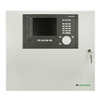
Securiton SecuriFire 2000 Mounting And Installation Manual (128 pages)
Fire Alarm Control Panel
Brand:
Securiton
| Category:
Control Panel
| Size: 5.64 MB
Table of Contents
Table of Contents
7
Technical Description
1
Fig. 117 Securilan Connection with Fibre Optics
5
Fig. 122 Connecting Securiline Extended
5
Fig. 123 Stub Line Connection
5
Fig. 37 B6-BCB, Connection of Inputs
5
Table of Contents
7
1 System Overview
13
Technical Data
15
Overview of Control Panels
15
Overview of System Limits
16
Overview of Securiline Extended Limits
16
2 Securifire 1000/2000 Control Panels
17
Map Case Design and Dimensions
17
Basic Design
17
Fig. 1 Map Case Design and Dimensions
17
B6-ADB 10 Additional Box
18
B6-MIC11 Built-In Control Panel
18
Mounting a Control Panel
18
Fig. 2 B6-ADB 10
18
Fig. 3 B6-MIC11
18
Fig. 4 Drilling Plan for All Securifire 1000/2000 Map Case Variants (All Dimensions in MM)
18
3 External Main Indication and Control Maps
19
Dimensions for External Indication and Control Maps (All Dimensions in MM)
19
Fig. 5 MIC711
19
Fig. 6 B5-MMI-FIP
19
Fig. 7 B5-MMI-FPS / B5-EPI-FPS
19
Fig. 8 B5-MMI-IPS
19
Fig. 9 B3-MMI-FAT / B5-EPI-FAT
19
Fig. 10 B5-MMI-FPD / B5-EPI-FPD
19
Fig. 11 B3-MMI-IPEL
19
Fig. 12 B3-MMI-EAT 64
19
Drilling Plans for External Indication and Control Maps
20
Fig. 19 MIC711
20
Fig. 20 B5-MIC-PPE / B5-EPI-FPC / EHB 701
20
Fig. 21 B3-MMI-IPEL / B3-MMI-EAT64
20
Fig. 22 B3-MMI-FAT
20
Fig. 23 B5-MMI-FPS / B5-MMI-IPS / B5-EPI-FPS
20
MIC711 Surface Mounting with Plan Box
21
Flush Mounting
21
Fig. 24 MIC711 / B5-EPI-FPC-GS with PLB 70-1
21
Fig. 25 FME73 with MIC711
21
Fig. 26 FME70 with MIC711 and PLB 70-1
21
4 Power Supply
22
Emergency Power Supply (Batteries)
22
Mains and Battery Connection
22
Fig. 27 230 V and Battery Connection
22
B6-PSU Power Supply Unit
23
Interfaces
23
Technical Data
23
Compatibility Information
23
Fig. 28 B6-PSU Interfaces
23
Connection of External Consumers
24
Battery Current Measurement
24
Fig. 29 Connection of External Consumers
24
Fig. 30 Battery Current Measurement
24
5 Main Control Units
25
B6-BCB12 Main Control Unit Securifire 1000
25
Interfaces
25
Fig. 31 B6-BCB12 Interfaces
25
Technical Data
26
Compatibility Information
26
Securifire 2000 B6-BCB13 Main Control Unit
27
Interfaces
27
Fig. 32 B6-BCB13 Interfaces
27
Technical Data
28
Compatibility Information
28
Connection of Monitored Inputs and Outputs
29
Technical Data
29
Fig. 33 B6-BCB, Input and Output Interface
29
Connection of Monitored Outputs to B6-BCB
30
Fig. 34 B6-BCB, Quiescent Current Monitored Loads
30
Fig. 35 B6-BCB, Electronic Loads
30
Fig. 36 B6-BCB, Connection with Feedback
30
Connection of Inputs to B6-BCB
31
Connection of Relay Outputs to
31
Technical Data
31
Fig. 38 B6-BCB, Interface for Relay Outputs
31
Connection Examples
32
Fig. 39 B6-BCB, Relay Output (Connection of 230 V Consumers)
32
Fig. 40 B6-BCB, Relay Output (Siren Connection)
32
Fig. 41 B6-BCB, Relay Output (Permanent Magnet Connection)
32
Extinguishing" Standard Interface Connection Compliant with Vds
33
Fig. 42 "Extinguishing" Standard Interface Connection
33
Fault" Standard Interface Connection Compliant with Vds
34
Fig. 43 "Fault" Standard Interface Connection (Variant 1)
34
Fig. 44 "Fault" Standard Interface Connection (Variant 2)
34
Fire Brigade Map Connection to B6-BCB Compliant with DIN 14661
35
Fig. 45 B6-BCB, Fire Brigade Panel Interface
35
Fig. 46 Connection of Fire Brigade Map 0720 (Wiesmeier)
35
Securiline Extended
36
Connector Plug for Securiline Extended
36
Technical Data
36
Compatibility Information
37
6 Expansion Units for Securifire 2000
38
B6-LXI2 Securiline Unit
38
Interfaces
38
Technical Data
38
Compatibility Information
38
Fig. 47 B6-LXI2 Interfaces
38
B4-DAI2 Securiline Unit
39
Interfaces
39
Technical Data
39
Compatibility Information
39
Fig. 48 B4-DAI2 Interfaces
39
B6-EIO Input/Output Unit
40
Interfaces
40
Connector Plugs for Detection Zones and Inputs (X2, X3)
40
Fig. 49 B6-EIO Interfaces
40
Fig. 50 Jumper Setting
41
Fig. 52 Jumper Setting
41
Connector Plug for Monitored Outputs (X4)
42
Connection Assignment for Plug (X4)
42
B4-EIO Input/Output Unit
43
Interfaces
43
Connector Plugs for Detection Zones and Inputs (X2, X3)
43
Fig. 51 B4-EIO Interfaces
43
Fig. 53 Jumper Setting
44
Connector Plug for Monitored Outputs (X4)
45
Connection Assignment for Plug (X4)
45
Connecting the Detector Series Securistar 521 / 523 / 563 and MCP
46
Connecting Detector Base USB 501
46
Connecting MCP 521N Manual Call Points
46
Connecting MCP 525 Manual Call Points
46
Connecting Detector Base 143 and 143K
46
Fig. 54 Connecting the Detector Series Securistar 521 / 523 / 563
46
Fig. 55 Connecting MCP 521N Manual Call Points
46
Fig. 56 Connecting MCP 525 Manual Call Points
46
Fig. 57 Connecting Detector Base 143 and 143K
46
Detector Base 143 Ex-I with Safety Barrier Z787
47
Detector Base 143 Ex-I with Direct Current Isolating Transformer GTW
47
Fig. 58 Detector Base 143 Ex-I with Safety Barrier Z787
47
Fig. 59 143 Ex-I Detector Base with GTW 01 Direct Current Isolating Converter
47
MMD130 Ex-I in Ex-Areas with Safety Barrier Z787
48
MMD130 Ex-I in Ex-Areas with Direct Current Isolating Transformer GTW
48
Fig. 60 Connecting MMD130 Ex-I Detectors in Ex Areas with Safety Barrier Z787
48
Fig. 61 Connecting MMD130 Ex-I Detectors in Ex Areas with GTW 01 Direct Current Isolating Converter
48
Connecting Hochiki Ex-I Detectors in Ex Areas
49
Fig. 62 Connecting Hochiki Ex-I Detectors in Ex Areas
49
Connecting Monitored Inputs
50
Monitored Input 26K7
50
Monitored Input 3K
50
Fig. 63 Monitored Input 26K7 Connection
50
Fig. 64 Connection of Monitored Input 3K
50
Connecting Extinguishing Inputs
51
Valve Monitoring
51
Extinguishing Input in Accordance with Vds
51
Connection of Monitored Outputs
51
Fig. 65 Valve Monitoring
51
Fig. 66 Extinguishing Input in Accordance with Vds
51
Fig. 67 Quiescent Current Monitored Outputs
51
Fig. 68 "Electronic Loads
51
Technical Data
52
Compatibility Information
52
B4-USI Universal Interface Unit
53
Interfaces
53
Technical Data
53
Fig. 69 B4-USI Interfaces
53
Compatibility Information
54
Plug Assignment with Screened Cabling
54
Fig. 70 Plug Assignment with Screened Cabling
54
Fig. 71 Plug Assignment with Screened Cabling
54
Plug Assignment with Unscreened Cabling
55
Fig. 72 Plug Assignment with Unscreened Cabling
55
Fig. 73 Plug Assignment with Unscreened Cabling
55
Connection to Management and Third-Party Systems (Non-Redundant)
56
Connecting Management System / ESPA to RS232 Interface
56
Connecting Management System /ESPA Via Converter
56
Fig. 74 Connecting Management System to RS232 Interface
56
Fig. 75 Connecting Management System / ESPA Via Converter
56
Connection to Management and Third-Party Systems (Redundant)
57
Connection to an Interface-Redundant Management System Via RS422
57
Fig. 76 Connecting Interface-Redundant Management System to RS422 Interface
57
Combox Connection
58
Serial Connection of the Combox to
58
Serial Connection of the Combox Via ADAM 4520
58
Fig. 77 Serial Connection of the Combox to B4-USI
58
Fig. 78 Serial Connection of the Combox Via ADAM 4520
58
Connection of the Combox to Securifire Via Contacts
59
Fig. 79 Connection of the Combox to Securifire Via Contacts
59
External Printer Connection
60
External Printer to RS232 Interface
60
External Parallel Printer on RS422 Interface with Converter
60
Fig. 80 External Printer on RS232 Interface
60
Fig. 81 External Parallel Printer on RS422 Interface with Converter
60
7 MMI-BUS Devices
61
MMI-BUS Schematic Drawing
61
MMI-BUS Technical Data
61
Fig. 82 MMI-BUS Schematic Drawing
61
Connection of MMI-BUS Participants
62
Jumper Assignment for MMI-BUS Termination
62
MMI-BUS Connection Open
62
Fig. 83 MMI-BUS Connection Open
62
MMI-BUS Connection Terminated
63
Fig. 84 MMI-BUS Connection Terminated
63
MMI-BUS Connection with Star-Shaped Power Supply
64
Fig. 85 MMI-BUS Connection with Star-Shaped Power Supply
64
B5-MMI-FIP Floor Panel
65
Interfaces
65
MMI Bus Power Supply Connector Plug (X1) and Power Supply (X2)
65
Fig. 86 B5-MMI-FIP
65
Fig. 87 B5-MMI-FIP Interfaces
65
Fig. 88 MMI Bus Power Supply Connector Plug (X1) and Power Supply (X2)
65
Instructions for Opening and Mounting the B5-MMI-FIP
66
Technical Data
66
Compatibility Information
66
Fig. 89 Front Side of B5-MMI-FIP
66
B5-MMI-FPS-S Fire Brigade Panel Sweden
67
Interfaces
67
MMI Bus Power Supply Connector Plug (X1) and Power Supply (X2)
67
Fig. 90 B5-MMI-FPS-S
67
Fig. 91 B5-MMI-FPS Interfaces
67
Fig. 92 MMI Bus Power Supply Connector Plug (X1) and Power Supply (X2)
67
Instructions for Opening and Mounting the B5-MMI-FPS-S
68
Technical Data
68
Compatibility Information
68
Fig. 93 Mounting B5-MMI-FPS-S
68
B3-MMI-UIO Universal Input/Output Module
69
Interfaces
69
MMI Bus Power Supply Connector Plug (X1) and Power Supply (X2)
69
Fig. 94 B3-MMI-UIO Interfaces
69
Fig. 95 MMI Bus Power Supply Connector Plug (X1) and Power Supply (X2)
69
Technical Data
71
Compatibility Information
71
B3-MMI-FAT Fire Brigade Indicator Board
72
Interfaces
72
Fig. 96 B3-MMI-FAT Interfaces
72
Technical Data
73
Compatibility Information
73
B5-MMI-FPCZ Fire Brigade Panel Czechia
74
Interfaces
74
Technical Data
74
Compatibility Information
74
Fig. 97 B5-MMI-FPCZ Interfaces
74
8 EPI-BUS Devices
75
Schematic of an EPI Bus
75
EPI Bus Features
75
Connection of EPI Bus Participants
75
B5-EPI-FPC-GS Swiss Fire Brigade Panel
76
Interfaces
76
Technical Data
76
Compatibility Information
76
Fig. 98 B5-EPI-FPC-GS
76
B5-EPI-ASP-GS Alarm Scrolling Panel for the Netherlands
77
Interfaces
77
Technical Data
77
Compatibility Information
77
Fig. 99 B5-EPI-ASP-GS
77
B5-EPI-FPS-S Fire Brigade Operating Panel for Sweden
78
Interfaces
78
Technical Data
78
Compatibility Information
78
Fig. 100 B5-EPI-FPS-S
78
Instructions for Opening and Mounting the B5-EPI-FPS-S
79
Fig. 101 Mounting B5-EPI-FPS-S
79
B5-EPI-PCM Partial Indication and Control Map
80
Interfaces
80
Technical Data
80
Compatibility Information
80
Fig. 102 B5-EPI-PCM
80
B5-EPI-PIM Partial Indication Map
81
Interfaces
81
Technical Data
81
Compatibility Information
81
Fig. 103 B5-EPI-PIM
81
B5-EPI-FAT Fire Brigade Indicator Board
82
Interfaces
82
Technical Data
82
Compatibility Information
82
Fig. 104 B5-EPI-FAT
82
B5-EPI-FPD Fire Brigade Control Panel
83
Interfaces
83
Technical Data
83
Compatibility Information
83
Fig. 105 B5-EPI-FPD
83
9 Securilan Network Units and MIC711
84
B6-NET2-485 Network Unit
84
Interfaces
84
Technical Data
84
Compatibility Information
84
Fig. 106 B6-NET2-485 Interfaces
84
B6-NET2-FXM and B6-NET2-FXS Network Units
85
Interfaces
85
Fig. 107 B6-NET2-FX Interfaces
85
Technical Data
86
Compatibility Information
86
B6-LAN Interface Unit
87
Interfaces
87
Technical Data
87
Compatibility Information
87
Fig. 108 B6-LAN Interfaces
87
Mic711
88
Fig. 109 Rear Side of B5-MIC711
88
Fig. 110 Rear Side of B6-MIC711
88
Fig. 111 Rear Side of B5-MIC485 Network Module
88
Fig. 112 Rear Side of B6-MIC485 Network Module
88
Power Supply Connection Plug (X1)
89
RS485 Plug Network Connection (X4)
89
Technical Data
89
Securilan Connection
90
Connection Types
90
Securilan Connection with RS485 Interfaces
91
Fig. 113 Line-Redundant Connections
91
Fig. 114 Securifire- Planning
91
Overview of the PIN Assignments of All Securilan Participants
92
Securilan Connection with 10/100TX Interface
93
Securilan Connection Via Ethernet Network (Logical Connection)
93
Fig. 115 Securilan Connection with 10/100TX Interface
93
Fig. 116 Non-Redundant Network
93
Securilan Connection with Fibre Optics
94
Example of Connecting a Securilan
95
Fig. 118 Example of Connecting a Securilan
95
Securifire Virtualmic Connection
96
Local Securifire Virtualmic Connection
96
Fig. 119 Securifire Virtualmic, Local Access Via LAN
96
Securifire Virtualmic Connection Via Switch
97
Securifire Virtualmic Access Via Intranet/Internet
97
Fig. 120 Securifire Virtualmic, Access Via Switch on B6-NET2-485
97
Fig. 121 Securifire Virtualmic, Access Via Intranet on B6-LAN
97
10 Securiline Extended
98
General
98
Max. Number of Participants Per Line Interface and Mode of Operation
99
Connection of Securiline Extended Modules
100
Stub Line Connection
101
Connecting Detector Base USB 501
101
Fig. 124 USB 501 Connection
101
Fig. 125 RAL720X Connection
101
Connection of MCP 535X and MCP 545X Manual Call Points
102
Connection of BX-AIM Advanced Input Module
102
Fig. 126 MCP 535X Connection
102
Fig. 127 MCP 545X Connection
102
Fig. 128 BX-AIM, Collective Detector and Monitored Input
102
Fig. 129 BX-AIM, Extinguishing Input Compliant with Vds
102
Fig. 130 BX-AIM, MMD130 Ex-I in Ex Area
102
BX-OI3 Output/Input Module Connection
103
Fig. 131 BX-OI3, Input/Output Module Connection
103
Fig. 132 BX-OI3, Connection of Special Detectors
103
BX-I2 Input Module Connection
104
Fig. 133 BX-I2, Input Module Connection
104
Fig. 134 BX-OI3, Connection of Special Detectors
104
BX-O1 Output Module Connection
105
BX-O2I4 Output / Input Module Connection
105
Fig. 135 BX-O1, Output Module Connection
105
Fig. 136 BX-O2I4, Output/Input Module Connection
105
BX-REL4 Relay Module Connection
106
10.3.10 BX-IOM Input/Output Module Connection
106
Fig. 137 BX-REL4, Relay Module Connection
106
Fig. 138 BX-IOM, Consumer with External Voltage Monitoring
106
10.3.11 BX-IM4 Input Module Connection
107
10.3.12 BX-RGW Radio Module Connection
107
Fig. 139 BX-IM4 Input Module Connection, Monitored Inputs
107
Fig. 140 BX-IM4 Input Module Connection, Unmonitored Inputs
107
Fig. 141 BX-RGW, Radio Module Connection
107
10.3.13 Connection of the BX-SOL Loop Siren
108
10.3.14 Loop Flashlight BX-FOL Connection
108
Fig. 142 BX-SOL, Loop Siren Connection
108
Fig. 143 BX-FOL, Loop Flashlight Connection
108
10.3.15 Connection of End Switch Module Extended Line BX-ESL
109
10.3.16 Connection for SDI81X / SDI82X Addressing Module
109
Fig. 144 BX-ESL, Connection
109
Fig. 145 SDI81X / SDI82X, Addressing Module Connection
109
10.3.17 Connection for BX-MDH Door Holding Magnet
110
10.3.18 Connection for BX-MDI8 Input Module
110
Fig. 146 BX-MDH, Door Holding Magnet Connection
110
Fig. 147 BX-MDI8, Input Module Connection
110
Fig. 148 BX-MDI8, Connecting Detector Base USB 501
111
Fig. 149 BX-MDI8, Connecting MCP 521N Manual Call Points
111
Fig. 150 BX-MDI8, Connecting MCP 525 Manual Call Points
111
Fig. 151 BX-MDI8, Connecting Detector Base USB501-7 Ex-I with Direct Current Isolating Transformer GTW 01
112
Fig. 152 BX-MDI8, Connecting the Detector Base 143 Ex-I with Direct Current Isolating Transformer GTW 01
112
Fig. 153 BX-MDI8, Connecting Surveyed Input 26K7 / Surveyed Input 3K
113
Fig. 154 BX-MDI8, Valve Monitoring / Extinguishing Input in Accordance with Vds
113
11 Programming and Software
114
Fig. 155 Securifire Studio
114
12 Annex
115
Recommended Cable Types
115
Data Cable for Securilan, Unscreened
115
Data Cable for MMI-BUS, Unscreened
115
Data Cable for MMI-BUS, Screened
115
Screened Addressable Loop Cable
115
Power Supply for MMI-BUS
116
Securilan Cable Specification
117
Fig. 156 F-UTP Cat5E
117
Fig. 157 F-UTP Cat5E
117
Fig. 158 F-UTP Cat5E
117
Fig. 159 UTP Cat5E
117
Crimping the RJ-45 Plug
118
Fig. 160 Example of MTRJ Type Plug
118
Fig. 161 Example of LC 2X5 Type Plug
118
Fig. 162 RJ-45 Plug and Pin Assignment
118
Fig. 163 RJ-45 Plug Assignment
118
Fig. 164 Crimp Plug
119
Fig. 165 Crimp Plug
119
Fig. 166 Crimp Plug
119
Fig. 167 Crimp Plug
119
Fig. 168 Crimp Plug
120
Fig. 169 Crimp Plug
120
Fig. 170 Crimp Plug
120
Fig. 171 Crimp Plug
120
Power Requirement Calculation
121
Fig. 172 Crimp Plug
121
Fig. 173 Crimp Plug
121
Fig. 174 Crimp Plug
121
Connection of FSS 800-1 Fire Brigade Key Box
122
Fig. 175 FSS 800-1 Connection Diagram
122
Protocol Printer
123
Changing Printer Paper
123
Replacing Ink Ribbon
123
Simple Troubleshooting
124
General
124
Contaminated Detector
124
Possible Causes of Faults
124
13 Article Numbers / Spare Parts
124
List of Figures 14 List of Figures
125
14 List of Figures
125
Advertisement
Advertisement
Related Products
Securiton SSD 535
Securiton SSD 535-1
Securiton SSD 535-2
Securiton SSD 535-3
Securiton SecuriFire 1000
Securiton Categories
Smoke Alarm
Control Panel
Remote Control
Water Filtration Systems
Fire Alarms
More Securiton Manuals
Login
Sign In
OR
Sign in with Facebook
Sign in with Google
Upload manual
Upload from disk
Upload from URL