Sign In
Upload
Manuals
Brands
Rohde & Schwarz Manuals
Measuring Instruments
FSP40
Rohde & Schwarz FSP40 Manuals
Manuals and User Guides for Rohde & Schwarz FSP40. We have
1
Rohde & Schwarz FSP40 manual available for free PDF download: Service Manual
Rohde & Schwarz FSP40 Service Manual (254 pages)
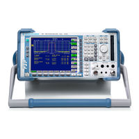
Spectrum Analyzer
Brand:
Rohde & Schwarz
| Category:
Measuring Instruments
| Size: 9.19 MB
Table of Contents
Contents - Chapter 1 "Performance Test"
27
Table of Contents
27
Performance Test
29
Test Instructions
29
Measurement Equipment and Accessories
29
Performance Test R&S FSP
32
Checking Reference Frequency Accuracy
32
Checking Immunity to Interference
32
1St if Image Frequency Rejection
33
2Nd if Image Frequency Rejection
33
3Rd if Image Frequency Rejection
33
1St if Rejection
34
2Nd if Rejection
34
Checking Nonlinearities
35
Third Order Intercept Point
35
Checking if Filters
36
Checking Bandwidth Switching Level Accuracy
36
Checking Bandwidth
37
Checking Shape Factor
37
Checking Noise Display
38
Checking Level Accuracy and Frequency Response
39
Checking Display Linearity
42
Checking RF Attenuator
44
Checking Reference Level Switching (if Gain)
45
Checking Phase Noise
47
Performance Test Option TV and RF Trigger: R&S FSP-B6
49
Checking RF Trigger
49
Checking TV Trigger
49
Performance Test Option Tracking Generator - R&S FSP-B9
50
Checking Output Level
50
Checking Frequency Response
51
Checking Modulation
52
Checking I/Q Modulation
52
Checking Amplitude Modulation
53
Checking Frequency Modulation
54
Performance Test Option WCDMA Demodulation Hardware - R&S FSP-B15
55
Checking Comb Line Level
55
Performance Test Option Electronic Attenuator- R&S FSP-B25
56
Checking Noise Display with Preamplifier (B25)
56
Checking Level Accuracy and Frequency Response with Preamplifier
57
Checking Frequency Response with Electronic Attenuator
60
Checking Nonlinearities with Electronic Attenuator
62
Third Order Intercept
62
Checking RF Attenuator (with Option B25)
63
Checking Electronic Attenuator Accuracy
64
Performance Test Option External Mixing R&S FSP-B21
65
Checking LO-Levels
65
Checking the Input lo
66
Out / if in (2-Port-Mixers)
66
Checking the Input if
66
In (3-Port-Mixers)
66
Checking the Bias Supply
67
Performance Test Report R&S FSP
68
Performance Test Report Option R&S FSP-B6
81
Performance Test Report Option R&S FSP-B9
82
Performance Test Report Option R&S FSP-B15
83
Performance Test Report Option R&S FSP-B25
84
Contents - Chapter 2 "Adjustment"
91
Adjustment
93
Service Menu
93
Entering the Password
94
Manual Adjustment
95
Test Instructions
95
Measuring Equipment and Accessories
95
Adjusting the Level Measurement Accuracy
96
Adjusting the Frequency Accuracy
98
Adjustment of Module Data
100
Frequency Response Correction
100
Contents - Chapter 3 "Repair"
101
Contents - Repair
103
Repair
105
Instrument Design and Function Description
105
Block Diagram
105
Fig. 3-1 Block Diagram
105
Attenuator
106
Description of Block Diagram
106
Electronic Attenuator (Option R&S FSP-B25)
106
RF to if Conversion for Frequencies < 3 Ghz - Frontend
107
Fig. 3-2 RF-To-IF Conversion for Frequencies < 3 Ghz
107
RF to if Conversion for Frequencies > 3 Ghz - Microwave Converter
108
Fig. 3-3 RF-To-IF Conversion for Frequencies > 3 Ghz
108
IF Filter - Module
109
Fig. 3-4 if Filter
109
OCXO Reference (Option R&S FSP-B4)
110
Reference Frequency
110
Reference Frequency 10 Mhz - if Filter Module
110
Reference Frequency 128 Mhz - if Filter Module
110
WCDMA Demodulation Hardware (Option R&S FSP-B15)
110
Processing of Measured Data - Detector Board
111
Fig. 3-6 Processing of Measured Data
111
AF Demodulation (Option R&S FSP-B3)
112
TV and RF Trigger (Option R&S FSP-B6)
112
Battery Pack (Option R&S FSP-B31/32)
113
DC Power Supply (Option R&S FSP-B30)
113
External Generator Control (Option R&S FSP-B10)
113
LAN Interface (Option R&S FSP-B16)
113
Tracking Generator (Option R&S FSP-B9)
113
Flash Disk (Option R&S FSP-B20)
114
Front Panel
114
Removable Hard Disk (Option R&S FSP-B18)
114
Motherboard
115
Power Supply Module
115
Module Replacement
116
Overview of the Modules
117
Performing a Cold Boot
118
Replacing the Front Module Controller A90
119
Fig. 3-7 Removing the Front Module Controller
120
Fig. 3-8 Installing a New Front Module Controller - Position of Connectors
121
Replacing the Lithium Battery on the Front Module Controller
122
Fig. 3-9 Position of Lithium Battery and Jumper 12 on the Front Module Controller
123
Replacing Hard Disk A60
125
Replacing the LCD and DC/AC Converter in the Front Module
126
Fig. 3-10 Position of Connectors on Front Module Controller
127
Replacing the Keyboard Membrane or Mat on the Front Module
128
Fig. 3-11 Position of Connectors on Front Module Controller
129
Replacing the Labelling Panel on the Front Module
130
Replacing the Floppy Disk Drive A30
131
Replacing the Power Supply A20
132
Replacing the Fan
133
Replacing the RF Input Connector (Cable W1)
134
Replacing the Motherboard A10
135
Replacing the Module RF Attenuator A40
137
Replacing the Key/Probe Module A80 and Vol./Phone Board A191 (Option R&S FSP-B3)
138
Fig. 3-12 Pin Assignments of PROBE POWER Connector
139
Replacing the RF Frontend A100
140
Replacing the Detector A120 or A140 (Option R&S FSP-B70)
141
Replacing the if Filter A130
142
Replacing the MW Converter Unit A160
143
Replacing Diplexer A162; R&S FSP7
144
Replacing 8 Ghz YIG Unit A161; R&S FSP7
145
Replacing Diplexer (30 Ghz) A230; R&S FSP13/30
147
Replacing 13/30 Ghz YIG Unit A161; R&S FSP13/30
148
Replacing RF Extension 13/30 A162; R&S FSP13/30
151
Replacing Diplexer A163; R&S FSP40
153
Replacing 40 Ghz YIG Unit A161; R&S FSP40
154
Replacing RF Extension 40 A162; R&S FSP40
156
Replacing AF Demodulator A190 (Option R&S FSP-B3)
157
Replacing the OCXO A200 (Option R&S FSP-B4)
158
Replacing Trigger A230 (Option R&S FSP-B6)
159
Replacing the Tracking Generator A170 (Option R&S FSP-B9)
160
Replacing the External Generator Control A210 (Option R&S FSP-B10)
161
Replacing Wideband Calibrator A190 (Option R&S FSP-B15)
163
Replacing the LAN Adapter (Option R&S FSP-B16)
164
Replacing Compact Flash Board S-ATA A60 (Option R&S FSP-B18)
165
Replacing Flash Disk A60 (Option R&S FSP-B20)
167
Replacing External Mixer Board A180 (Option B21)
168
Replacing the Electronic Attenuator A50 (Option R&S FSP-B25)
169
Replacing the DC/DC Converter Option R&S FSP-B30)
170
Replacing the Battery Charger Module (Option R&S FSP-B31/32)
171
Replacing the Batteries (Option R&S FSP-B31/32)
172
Measuring Equipment and Accessories
173
Troubleshooting Start-Up Problems
174
Troubleshooting Problems with Boot Process
175
Troubleshooting - Loading Module Eeproms
181
Troubleshooting Via Selftest
183
Troubleshooting Frontend 1
195
Troubleshooting
196
Troubleshooting - MW Converter
196
Contents - Chapter 4 "Software Update/Installing Options"
197
Software Update / Installing Options
199
Installation of New R&S FSP Software
199
Restoring the Operating-System Installation
200
Installing the Options
202
Contents - Chapter 5 "Documents"
203
Fig
203
Documents
205
Shipping of Instrument and Ordering of Spare Parts
205
Shipping of Instrument
205
Shipping of a Module
205
Ordering Spare Parts
206
Refurbished Modules
206
Return of Defective Replaced Modules
206
Spare Parts
207
Available Power Cables
207
Spare Parts List
209
Mechanical Drawings
209
Block Circuit Diagram
247
Advertisement
Advertisement
Related Products
Rohde & Schwarz R&S FSP-B10
Rohde & Schwarz FSP3
Rohde & Schwarz FSP7
Rohde & Schwarz FSP13
Rohde & Schwarz FSP30
Rohde & Schwarz FSP31
Rohde & Schwarz FSPN
Rohde & Schwarz FSPN8
Rohde & Schwarz FSPN26
Rohde & Schwarz R&S FSP-B28
Rohde & Schwarz Categories
Measuring Instruments
Test Equipment
Portable Generator
Power Supply
Accessories
More Rohde & Schwarz Manuals
Login
Sign In
OR
Sign in with Facebook
Sign in with Google
Upload manual
Upload from disk
Upload from URL