Sign In
Upload
Manuals
Brands
Rockwell Automation Manuals
Servo Drives
Allen-Bradley 2094-BM02-S
Rockwell Automation Allen-Bradley 2094-BM02-S Manuals
Manuals and User Guides for Rockwell Automation Allen-Bradley 2094-BM02-S. We have
1
Rockwell Automation Allen-Bradley 2094-BM02-S manual available for free PDF download: User Manual
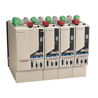
Rockwell Automation Allen-Bradley 2094-BM02-S User Manual (280 pages)
Multi-axis Servo Drives
Brand:
Rockwell Automation
| Category:
Servo Drives
| Size: 12.11 MB
Table of Contents
Table of Contents
5
About this Publication
11
Conventions Used in this Manual
11
Who Should Use this Manual
11
Additional Resources
12
Chapter 1 Introduction
13
IAM/AM Module Series Change
13
About the Kinetix 6000 Drive Systems
14
Typical Hardware Configurations
15
Typical Communication Configurations
18
Catalog Number Explanation
19
Drive Component Compatibility
20
Agency Compliance
21
CE Requirements (System Without LIM Module)
21
CE Requirements (System with LIM Module)
22
Introduction
23
Chapter 2 System Design Guidelines
24
System Mounting Requirements
24
Transformer Selection
25
Circuit Breaker/Fuse Selection
26
Enclosure Selection
27
Minimum Clearance Requirements
30
Electrical Noise Reduction
31
Bonding Modules
31
Bonding Multiple Subpanels
33
Establishing Noise Zones
34
Cable Categories for Kinetix 6000 Systems
41
Noise Reduction Guidelines for Drive Accessories
43
Introduction
47
Chapter 3
47
Using the 2094 Mounting Brackets
47
Installing the 2094 Power Rail
48
Determine Mounting Order
48
Mount Modules on the Power Rail
49
Introduction
53
Chapter 4 IAM/AM Module Features
54
Safe-Off Connector Pinout
56
I/O Connector Pinout
57
Motor Feedback Connector Pinout
58
Auxiliary Feedback Connector Pinout
60
IAM Input Connector Pinout
61
IAM and am Motor Power and Brake Connector Pinout
62
Control Signal Specifications
63
Digital Inputs
63
SERCOS Communication Specifications
64
Analog Outputs
65
Contactor Enable Relay
66
Power and Relay Specifications
67
Motor/Resistive Brake Relay
67
Input Power Cycle Capability
68
Peak Enhancement Specifications
69
Control Power
72
Feedback Specifications
73
Absolute Position Feature
73
Feedback Power Supply Specifications
75
Auxiliary Position Feedback Encoders
76
Chapter 5
77
Introduction
77
Basic Wiring Requirements
77
Building Your Own Cables
78
Routing the Power and Signal Cables
78
Determine the Input Power Configuration
79
Grounded Power Configurations
79
Ungrounded Power Configurations
81
DC Common Bus Configurations
82
Common Bus Fusing Requirements
83
Setting the Ground Jumper in Ungrounded Power Configurations
83
Set the Ground Jumper
84
Grounding the Kinetix 6000 Drive System
89
Ground the Power Rail to the System Subpanel
89
Ground Multiple Subpanels
90
Power Wiring Requirements
91
Power Wiring Guidelines
93
Wiring the IAM/AM Module Connectors
94
Wire the Control Power (CPD) Connector
94
Wire the Input Power (IPD) Connector
95
Wire the Contactor Enable (CED) Connector
97
Wiring the Safe-Off (SO) Connector
98
Wire the Motor Power (MP) Connector
99
Wire the Motor/Resistive Brake (BC) Connector
106
Apply the Motor Cable Shield Clamp
109
Feedback and I/O Cable Connections
110
Flying-Lead Feedback Cable Pin-Outs
112
Wiring the Feedback and I/O Connectors
115
Connect Premolded Motor Feedback Cables
115
Connect Panel-Mounted Breakout Board Kits
116
Wire Low-Profile Connector Kits
117
External Shunt Module Connections
120
RBM Module Connections
121
SERCOS Fiber-Optic Cable Connections
122
Installing the Fiber-Optic Connector Bracket Kit
125
Connecting the Kinetix 6000 Drive System
77
Chapter 6
127
Introduction
127
Configure the Drive Modules
128
Configure the Logix SERCOS Interface Module
133
Configure the Logix Controller
133
Configure the Logix Module
135
Configure the Kinetix 6000 Drive Modules
137
Configure the Motion Group
141
Configure Axis Properties
142
Download the Program
146
Apply Power to the Kinetix 6000 Drive
146
Test and Tune the Axes
148
Test the Axes
148
Tune the Axes
150
Configure Drive Parameters and System Variables
153
Tools for Changing Parameters
153
Monitor System Variables with Analog Test Points
154
Configure and Start up the Kinetix 6000 Drive System
127
Chapter 7
157
Introduction
157
Safety Precautions
157
Interpret Status Indicators
158
Error Codes
158
IAM/AM Module Status Indicators
164
Shunt Module Status Indicators
165
General System Anomalies
167
Logix/Drive Fault Behavior
169
Introduction
173
Troubleshooting the Kinetix 6000 Drive System
157
Chapter 8
173
Before You Begin
173
Remove Kinetix 6000 Drive Modules
174
Replace Kinetix 6000 Drive Modules
175
Remove the Power Rail
176
Replace the Power Rail
177
Introduction
179
Appendix A Power Specifications
180
Integrated Axis Module (Converter) Power Specifications
180
Axis Module (Inverter) Power Specifications
182
Shunt Module Power Specifications
184
Circuit Breaker/Fuse Specifications
187
Contactor Ratings
188
Transformer Specifications for Control Power Input
188
Power Dissipation Specifications
189
General Specifications
190
Maximum Feedback Cable Lengths
190
Maximum Power Cable Length
191
Weight Specifications
192
Certifications
192
Environmental Specifications
193
AC Line Filter Specifications
193
External Shunt Module Specifications
194
Product Dimensions
195
Appendix B
199
Introduction
199
Interconnect Diagram Notes
200
Power Wiring Examples
201
DC Common Bus Wiring Examples
205
Shunt Module Wiring Examples
209
Axis Module/Rotary Motor Wiring Examples
212
Axis Module/Linear Motor/Actuator Wiring Examples
220
Controlling a Brake Example
224
System Block Diagrams
225
Introduction
229
Appendix C Upgrade Drive Firmware with Controlflash Software
230
Before You Begin
230
Configure Logix Communication
231
Flash Firmware
233
Verify the Firmware Upgrade
237
Upgrade Drive Firmware with Driveexplorer Software
238
Before You Begin
238
Select Axis Modules to Upgrade
238
Hyperterminal Configuration
240
Flash Firmware
242
Introduction
245
Appendix D
245
Before You Begin
245
Calculate Total Bus Capacitance
246
Calculate Additional Bus Capacitance
247
Bulletin 2094 Drive Capacitance Values
247
Common Bus Capacitance Example
248
Set the Additional Bus Capacitance Parameter with
249
Driveexplorer Software
249
Remove SERCOS Communication
249
Set the Additional Bus Capacitance Parameter
250
Save the Add Bus Cap Parameter to Non-Volatile Memory
251
Reconnect SERCOS Communication
252
Introduction
253
Appendix E
253
Before You Begin
253
Change IDN Parameter Values
254
Read the Present IDN Parameter Value
254
Calculate the New IDN Value
256
Write the New IDN Parameter Value
257
Introduction
259
Appendix F
259
Before You Begin
259
RBM Module Wiring Examples
260
Advertisement
Advertisement
Related Products
Rockwell Automation Allen-Bradley 2094-BC01-MP5-S
Rockwell Automation Allen-Bradley 2094-BMP5-S
Rockwell Automation Allen-Bradley 2094-BC01-M01-S
Rockwell Automation Allen-Bradley 2094-BM01-S
Rockwell Automation Allen-Bradley 2094-BC02-M02-S
Rockwell Automation Allen-Bradley 2094-BC04-M03-S
Rockwell Automation Allen-Bradley 2094-BM03-S
Rockwell Automation Allen-Bradley 2094-BC07-M05-S
Rockwell Automation Allen-Bradley 2094-BM05-S
Rockwell Automation Allen-Bradley 2098-DSD-HV150
Rockwell Automation Categories
Controller
Control Unit
Power Supply
DC Drives
Industrial Equipment
More Rockwell Automation Manuals
Login
Sign In
OR
Sign in with Facebook
Sign in with Google
Upload manual
Upload from disk
Upload from URL