Sign In
Upload
Manuals
Brands
Pfeiffer Vacuum Manuals
Measuring Instruments
TPG 361
Pfeiffer Vacuum TPG 361 Manuals
Manuals and User Guides for Pfeiffer Vacuum TPG 361. We have
3
Pfeiffer Vacuum TPG 361 manuals available for free PDF download: Operating Instructions Manual, Translation Of The Original Instructions
Pfeiffer Vacuum TPG 361 Operating Instructions Manual (72 pages)
Total pressure measuring and control unit
Brand:
Pfeiffer Vacuum
| Category:
Control Unit
| Size: 7.3 MB
Table of Contents
Table of Contents
3
1 About this Manual
7
Validity
7
Applicable Documents
7
Variants
7
Firmware Versions
7
Target Group
7
Conventions
8
Instructions in the Text
8
Pictographs
8
Product Labels
8
Abbreviations
8
Trademarks
9
Tbl. 3: Abbreviations Used
9
2 Safety
10
General Safety Instructions
10
Safety Instructions
10
Tbl. 4: Danger to Life Due to Electric Voltage
11
Fig. 1: Disconnect Device in Accordance with en 61010-1
11
Safety Precautions
14
Proper Use
15
Foreseeable Improper Use
15
Responsibilities and Warranty
15
Owner Requirements
15
Personnel Qualification
16
Ensuring Personnel Qualification
16
Personnel Qualification for Maintenance and Repair
16
Advanced Training with Pfeiffer Vacuum
17
Operator Requirements
17
3 Transportation and Storage
18
4 Product Description
19
Identifying the Product
19
Scope of Delivery
19
Design, Construction
19
Fig. 2: Front Panel
19
Display Elements
20
Fig. 3: Connections on the Rear Side
20
Fig. 4: Display
20
Fig. 5: Parameter or Bar Graph
21
Fig. 6: Switch-Points, Parameter Mode and Input Lock
21
Controls
22
Interfaces
22
Mains Power Supply
22
Fig. 7: Measurement Channel Status
22
Ground Terminal
23
Sensor" Connection
23
Control" Connection
23
Fig. 8: Mains Connection with IEC 320 C13 Socket
23
Fig. 9: Gauge Connection (6-Pin Amphenol C 091 B Socket)
23
Relay" Connection
24
Tbl. 6: Switching Functions
24
Fig. 10: "Control" Connection (7-Pin Amphenol C 091 B Socket)
24
Fig. 11: "Relay" Connection (15-Pole D-Sub Socket)
24
Connection "RS-485
25
USB" Connection (Type B)
25
USB" Connection (Type A)
25
Fig. 12: "RS-485" Connection (5-Pole Binder M12 Socket)
25
Fig. 13: "USB" Connection (Type B)
25
Fig. 14: "USB" Connection (Type A)
25
Ethernet" (LAN) Connection
26
Fig. 15: "Ethernet" (LAN) Connection
26
5 Installation
27
Installing the Device in a 19" Rack
27
Fig. 16: Guide Rails
27
Fig. 17: Rack Module Adapter (3 Height Units)
27
Installing the Device in a Switchboard
28
Fig. 18: Device Installation
28
Using the Device as a Desktop Device
29
Fig. 19: Required Control Panel Cut-Out
29
Fig. 20: Fastening the Rubber Feet and Rubber Strip
30
6 Commissioning
31
Switch on the Device
31
Updating the Firmware
31
Fig. 21: USB Update Tool
32
Configuring Ethernet
33
Fig. 22: Ethernet Configuration Tool
34
7 Operation
36
Basic Operation
36
Operating Modes
36
Measuring Mode
36
Tbl. 9: Description of the Controls
36
Fig. 23: Change Measurement Channel (Only for TPG 362)
37
Fig. 24: Switching Gauges on and off
37
Fig. 25: Measurement Range
37
Parameter Mode
38
Fig. 26: Identifying the Gauge
38
Fig. 27: Change from Measuring Mode to Parameter Mode
38
Fig. 28: Select Parameter Group
38
Fig. 29: Read/Write Parameter Groups and Parameters
39
Switching Function Parameters
40
Tbl. 10: Parameters in the "Switching Function Parameters" Group
40
Tbl. 11: Examples of Switching Function Displays
40
Gauge Parameters
41
Fig. 30: Switching Functions and Threshold Values
41
Tbl. 13: Parameters in the "Gauge Parameters" Group
42
Tbl. 14: Parameters Available in the "Gauge Parameters" Group
42
Gauge Control
43
Tbl. 15: Parameters in the "Gauge Control" Group
43
Fig. 31: Measured Value Filter Fast, Normal and Slow (from Left to Right)
43
General Parameters
45
Tbl. 18: Switch-Off Type (S-OFF)
45
Tbl. 19: Switch On/Off Thresholds
45
Tbl. 20: Parameters in the "General Parameters" Group
45
Fig. 32: Load Factory Settings: Press the Arrow Keys Simultaneously > 2 Seconds
48
Test Parameters
49
Tbl. 22: Parameters in the "Test Parameters" Group
49
Fig. 33: Program Memory Test
50
Fig. 34: Parameter Memory Test
50
Data Logger Mode
51
Fig. 35: Display Test
51
Fig. 36: Test of Relays in the Device
51
Tbl. 23: Parameters in Data Logger Mode
52
Fig. 37: Start/Stop Measured Data Recording
52
Setup Mode
53
Tbl. 24: Parameters in Setup Mode
53
Fig. 38: Delete Files
53
Fig. 39: Formatting the USB Memory Stick
54
Fig. 40: Delete Parameter Files from the USB Memory Stick
54
8 Decommissioning
55
9 Maintenance
56
Cleaning the Device
56
Replacing the Battery
57
10 Errors
58
Tbl. 25: Errors
58
11 Shipping
59
12 Disposal
60
13 Service Solutions from Pfeiffer Vacuum
61
14 Technical Data and Dimensions
63
Technical Data
63
Tbl. 26: Technical Data (General)
63
Tbl. 27: Technical Data (Mains Connection)
63
Tbl. 28: Technical Data (Ambient Conditions)
63
Tbl. 29: Technical Data (Gauge Connections)
64
Tbl. 30: Technical Data (Gauge Supply)
64
Tbl. 31: Technical Data (Operation)
64
Tbl. 32: Technical Data (Measured Values)
64
Tbl. 33: Technical Data (Switching Functions)
65
Tbl. 34: Technical Data (Switching Function Relay)
65
Tbl. 35: Technical Data (Error Signal (Error))
65
Tbl. 36: Technical Data (Error Signal Relay)
65
Tbl. 37: Technical Data (Gauge Control)
66
Tbl. 38: Technical Data (Analog Outputs)
66
Tbl. 39: Technical Data (RS-485 Interface)
66
Tbl. 40: Technical Data (USB Interface (Type A))
66
Dimensions
67
Tbl. 41: Technical Data (USB Interface (Type B))
67
Tbl. 42: Technical Data (Ethernet Interface)
67
Fig. 41: Dimensions TPG 361 (in MM)
67
Fig. 42: Dimensions TPG 362 (in MM)
68
15 Appendix
69
Units of Pressure
69
Gas Throughputs
69
ETL Listed
70
Declaration of Conformity
71
Advertisement
Pfeiffer Vacuum TPG 361 Translation Of The Original Instructions (40 pages)
Communication Protocol, Mnemonics and Protocol for Single- and Dual-Channel Measurement and Control Units for ActiveLine Gauges
Brand:
Pfeiffer Vacuum
| Category:
Industrial Equipment
| Size: 0.53 MB
Table of Contents
CF1 Calibration Factor Gauge
1
PR1 Measurement Data Gauge
1
Product Identification
2
Validity
2
Intended Use
2
Trademark
2
CF2 Calibration Factor Gauge
2
PR2 Measurement Data Gauge
2
Contents
3
Table of Contents
3
1 Mnemonics Protocol
5
Installation
5
Data Transmission
5
Communication Protocol
6
Mnemonics
7
Measurement Mode
8
COM - Continuous Output of Measurement Values
8
CPR - Combined Pressure Range (Linear Gauges, TPG 362 Only)
9
ERR - Error Status
10
ERR Error Status
10
PR1, PR2 - Measurement Data Gauge 1 or
10
PRX - Measurement Data Gauges 1 and
11
RES - Reset
11
RES Reset
11
SEN - Gauge On/Off
12
SEN Gauge On/Off
12
TID - Gauge Identification
12
Switching Function Parameters
13
SPS - Switching Function Status
13
Sp1
13
Gauge Parameters
14
CAL - Calibration Factor
14
CAL Calibration Factor
14
DCD - Display Resolution
14
DCD Display Resolution
14
DGS - Degas
15
DGS Degas
15
FIL - Measurement Value Filter
15
FIL Measurement Value Filter
15
FSR - Measurement Range (Linear Gauges)
16
FSR Measurement Range (Linear Gauges)
16
GAS - Gas Type Correction
16
GAS Gas Type Correction
16
OFC - Offset Correction (Linear Gauges)
17
OFC Offset Correction (Linear Gauges)
17
OFD - Offset Display (Linear Gauges)
17
OFD Offset Display (Linear Gauges)
17
Gauge Control
18
SC1, SC2 - Gauge 1 and 2 Control
18
General Parameters
18
BAL - Backlight
18
BAL Backlight
18
SC1 Gauge 1 Control
18
SC2 Gauge 2 Control
18
BAU - Transmission Rate (USB)
19
BAU Transmission Rate (USB)
19
DCB - Display Control Bar Graph
20
DCB Display Control Bar Graph
20
DCC - Display Control Contrast
21
DCC Display Control Contrast
21
DCS - Display Control Screensave
21
DCS Display Control Screensave
21
ERA - Error Relay Allocation
22
ERA Error Relay Allocation
22
EVA - Measurement Range End Value
22
EVA Measurement Range End Value
22
FMT - Number Format (Measurement Value)
22
FMT Number Format (Measurement Value)
22
LNG - Language (Display)
23
LNG Language (Display)
23
NAD - Node (Device) Address for RS485
23
NAD Node (Device) Address for RS485
23
PRE - Pirani Range Extension
23
PRO - Protocol Serial Interface
24
PUC - Penning Underrange Control
24
PUC Penning Underrange Control
24
SAV - Save Parameters (EEPROM)
24
SAV Save Parameters (EEPROM)
24
UNI - Pressure Unit
25
Data Logger Parameters
25
DAT - Date
25
DAT Date
25
LCM - Start / Stop Data Logger
26
LCM Start / Stop Data Logger
26
TIM - Time
26
Group Setup
27
SCM - Save / Load Parameters (USB)
27
SCM Save / Load Parameters (USB)
27
Test Parameters
27
ADC - A/D Converter Test
27
CDA - Re-Calibration
27
CDA Re-Calibration
27
DIS - Display Test
28
DIS Display Test
28
EEP - EEPROM Test
28
EEP EEPROM Test
28
EPR - FLASH Test
28
EPR FLASH Test
28
HDW - Hardware Version
28
HDW Hardware Version
28
IOT - I/O Test
29
IOT I/O Test
29
LOC - Keylock
29
LOC Keylock
29
MAC - Ethernet MAC Address
30
MAC Ethernet MAC Address
30
PNR - Firmware Version
30
PNR Firmware Version
30
RHR - Operating Hours
30
RHR Operating Hours
30
TAI - Test A/D Converter, ID Resistance
30
TKB - Operator Key Test
31
TLC - Torr Lock
31
TMP - Inner Temperature of the Unit
31
WDT - Watchdog Control
32
Further
32
AYT - Are You There
32
AYT Are You There
32
ETH - Ethernet Configuration
32
ETH Ethernet Configuration
32
Example
33
2 Pfeiffer Vacuum Protocol
34
Telegram Frame
34
Telegrams
35
Master Telegrams
35
Slave Telegrams
35
Data Types
36
Parameters
37
3 Appendix
38
A: Literature
38
Pfeiffer Vacuum TPG 361 Operating Instructions Manual (68 pages)
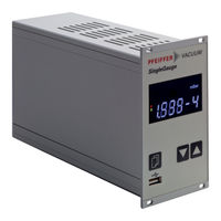
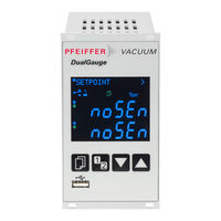
SingleGauge, DualGauge, Single- and Dual-Channel Measurement and Control Unit for ActiveLine Transmitter
Brand:
Pfeiffer Vacuum
| Category:
Measuring Instruments
| Size: 2.57 MB
Table of Contents
Product Identification
2
Validity
2
Intended Use
3
Scope of Delivery
3
Trademark
3
Table of Contents
4
1 Safety
5
Symbols Used
5
Personnel Qualifications
5
General Safety Instructions
6
Liability and Warranty
6
2 Technical Data
7
3 Installation
11
Personnel
11
Installation, Setup
11
Rack Installation
11
Installation in a Control Panel
12
Use as Desk-Top Unit
13
Mains Power Connector
14
Gauge Connectors Sensor 1, Sensor
14
Control Connector
15
Relay Connector
16
Interface Connector RS485
17
Interface Connector USB Type B
17
Interface Connector USB Type a
17
Interface Connector Ethernet
18
4 Operation
19
Front Panel
19
Turning the TPG 36X on and off
20
Operating Modes
21
Measurement Mode
22
Parameter Mode
24
Switching Function Parameters
25
Gauge Parameters
27
Gauge Control
34
General Parameters
39
Test Parameters
45
Data Logger Mode
48
Setup Mode
50
5 Maintenance
53
6 Troubleshooting
54
7 Repair
55
8 Storage
55
9 Disposal
55
Appendix
56
A: Conversiontables
56
B: Firmware Update
57
C: Ethernet Configuration
60
D: Literature
62
ETL Certification
64
EC Declaration of Conformity
65
Advertisement
Advertisement
Related Products
Pfeiffer Vacuum TPG 362
Pfeiffer Vacuum TPG 202
Pfeiffer Vacuum TPG 201
Pfeiffer Vacuum TPG 202 NEO
Pfeiffer Vacuum TPR 280
Pfeiffer Vacuum TPR 281
Pfeiffer Vacuum TPR 265
Pfeiffer Vacuum TTR 91
Pfeiffer Vacuum TTR 91 S
Pfeiffer Vacuum THERMOSTAR
Pfeiffer Vacuum Categories
Water Pump
Control Unit
Measuring Instruments
Industrial Equipment
Security Sensors
More Pfeiffer Vacuum Manuals
Login
Sign In
OR
Sign in with Facebook
Sign in with Google
Upload manual
Upload from disk
Upload from URL