Sign In
Upload
Manuals
Brands
MirCom Manuals
Control Panel
FA-300 Series
MirCom FA-300 Series Alarm Control Panel Manuals
Manuals and User Guides for MirCom FA-300 Series Alarm Control Panel. We have
7
MirCom FA-300 Series Alarm Control Panel manuals available for free PDF download: Installation And Operation Manual, User Manual
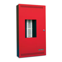
Mircom FA-300 Series Installation And Operation Manual (106 pages)
LED Fire Alarm Control Panel
Brand:
Mircom
| Category:
Control Panel
| Size: 6.54 MB
Table of Contents
Table of Contents
3
1 Industry Canada and FCC Notice
9
Notice for All FA-300 Series Built-In Udacts Sold in Canada
9
Industry Canada Notice
9
Notice for All FA-300 Series Built-In Udacts Sold in the U.S.A
9
2 Introduction
11
Overall Features
11
3 Conventions
12
Circuits
12
Zone
12
Display Points
12
Wiring Styles
12
4 System Components
13
Main Fire Control Panel
13
Figure 1 FA-300 LED Series
13
Table 1 FA-300 LED Series Comparison Chart
13
Relay Module: 12 Relays
14
Relay Modules: Six Relays
14
Polarity Reversal/City Tie
14
Remote Annunciator
14
Smart Relay Module
15
Input Class a Converter: Six Circuits
15
Output Class a Converter: Four Circuits
15
Output Class a Converter: Two Circuits
15
4.10 Active End-Of-Line Resistors
16
Remote Annunciator
16
4.12 Additional Fire Alarm System Accessories
16
5 Mechanical Installation
17
Installing the Enclosure
17
Figure 2 Box Dimensions, Surface Mount
17
Figure 3 Box Dimensions, Semi-Flush Mounting and Trim Ring
18
Figure 4 Flush Trim Detail (from Above)
18
BBX-1024DS and BBX-1024DSR Mechanical Installation
19
Figure 5 BBX-1024DS and BBX-1024DSR Installation Instructions and Dimensions
19
Installing the Adder Modules
20
Figure 6 Installation of Adder Modules
20
6 Cable and Jumper Connections for Main Board and Adder Modules
21
Main Fire Alarm Board
21
Figure 7 Main Fire Alarm Board Cable Connector and Jumper Settings
21
Figure 29 LAMP TEST
21
ICAC-306 Input Class-A Converter Adder Module
22
Figure 8 ICAC-306 Input Class-A Converter Adder Module
22
OCAC-304/302 Output Class-A Converter Adder Module
23
Relay Adder Modules
23
Figure 9 OCAC-304/302 Output Class-A Converter Adder Module
23
Figure 10 RM-312 Twelve Relay Adder Module
24
Figure 11 RM-312/306 Relay Programming
24
Polarity Reversal and City Tie Module (Model PR-300)
25
Figure 12 RM-306 Six Relay Adder Module
25
Figure 13 Polarity Reversal and City Tie Module
25
7 Field Wiring
27
Main Fire Alarm Board Field Wiring
27
Figure 14 Initiating Circuit - Class B or Style B Wiring
27
Figure 15 Initiating Circuit- Class a or Style D Wiring
28
Figure 16 Indicating Circuit - Class B or Style y Wiring
29
Figure 17 Indicating Circuit -Class a or Style Z Wiring
29
Figure 18 Four-Wire Smoke Detector Wiring
30
Figure 19 Dialer Wiring
30
Relay Adder Module Wiring
31
Figure 20 Relay Per Zone (RM-312) Terminal Connection
31
Figure 21 Relay Per Zone (RM-306) Terminal Connection
31
Connecting to a 3G4010 Interface Device for Canada
32
Figure 22 Connecting an FA-300 FACP to a 3G4010 Interface Device
32
Connecting to a 3G4010CF Interface Device Outside Canada
33
Figure 23 Connecting an FACP to a 3G4010CF Interface Device Outside Canada
33
Polarity Reversal and City Tie Module (PR-300) Wiring
34
Figure 24 Polarity Reversal and City Tie Module Terminal Connection
34
Power Supply Connection
35
Figure 25 Power Supply Connection
35
Table 2 Power Supply Ratings
35
Wiring Tables and Information
36
Table 3 Initiating Circuit Wiring
36
Table 4 Indicating Circuit Wiring
36
Four-Wire Smoke Power
37
Supervised Auxiliary Power
37
7.10 Auxiliary Power
37
Table 5 RS-485 Wiring to Annunciators and Other Devices
37
8 Turning on the Panel
38
Before Connecting the Power
38
Power-Up Procedure
38
Figure 26 Battery Connections
39
Troubleshooting
40
9 Indicators, Controls and Operations
41
Figure 27 LED Indicators and Control Buttons
41
Common Indicators
42
Indicating Circuit Indicators
45
Figure 28 Alarm Circuit Indicator
45
Table 6 Alarm Circuit Indicators
45
Table 7 Supervisory Circuit Indicators
45
Table 8 Property and Building Safety Indicators
46
Signal Circuit Indicators
47
Common Controls
47
Table 9 Trouble-Only Circuit Indicators
47
Table 10 Signal Circuit Indicators
47
Circuit (Zone) Disconnect Buttons
49
Common Relays
50
Circuit Types
50
Indicating (Signal) Circuit Types
52
Evacuation Codes (Signal Rates)
52
9.10 Single Stage Operation
53
Figure 30 Evacuation and Alert Codes
53
9.11 Two-Stage Operation
54
10 Supported Protocols/Devices
56
10.1 Synchronous Strobes
56
System Sensor's I3 Devices
56
Figure 31 Open Circuit Trouble
57
Figure 32 Communication Trouble
57
Figure 33 Dirty Device Trouble
57
Figure 34 out of Sensitivity Trouble
57
Figure 35 Freeze Trouble
58
Table 11 I3 Smoke Detector Leds
58
11 Configuration with the CFG-300 LCD Service Tool
59
Table 12 Settings Permitted in CAN/ULCS527
59
Table 13 Settings Permitted in UL864
59
11.1 Accessing Configuration Mode
60
Figure 36 FA-300 Configuration
60
11.2 Command Menu
61
Figure 37 Enter Passcode
61
Figure 38 Command Menu
61
CONFIG (Command-Menu)
62
Figure 39 FA-300 Config Menu
62
Figure 40 Feature Config Menu
63
Table 14 Feature Config Menu
63
Config Info
72
Set Time (Command-Menu)
73
Change Password (Command-Menu)
75
View Event Log (Command-Menu)
75
Figure 41 the Event Log
75
Clear Event Log (Command-Menu)
76
Walk Test (Command-Menu)
76
Figure 42 Select Log
76
Figure 43 Clear All the Selected Logs
76
Figure 44 Logs Cleared
76
Figure 45 Walk Test Confirmation
76
Figure 46 Walk Test Zones
77
Figure 47 Walk Test Active
77
I3 Loop Test (Command-Menu)
78
Figure 48 I3 Loop Test Confirmation
78
Figure 49 I3 Test Zones
78
Figure 50 I3 Test Not Ready
78
Figure 51 the Selected Zone Is Not I3 Type
78
Dialer Config (Command-Menu)
79
Figure 52 Dialer Config Menu
79
Table 15 I3 Detector Statuses
79
Test Dialer (Command-Menu)
87
Exit (Command-Menu)
88
11.14 CFG-300 LCD Service Tool Operation
88
11.15 Zone Messages
89
Figure 53 Detection Circuit Zone Message
89
Figure 54 Indicating Circuit Zone Message
89
11.16 AC Power Fail
90
Battery Trouble
90
Figure 55 AC Power Fail
90
Figure 56 Battery Trouble
90
11.18 Ground Fault
91
11.19 Remote Annunciator
91
11.20 Four-Wire Smoke Detector Supply
91
Figure 57 Ground Fault
91
Figure 58 Remote Annunciator Mismatch Trouble
91
11.21 Supervised Aux. Supply
92
11.22 City Tie Polarity Reversal - PR-300/ Relay Module
92
Figure 59 Four-Wire Power Supply
92
Figure 60 Aux. Power Supply
92
Figure 61 City Tie Module Missing
93
Figure 62 City Tie Trouble
93
12 Appendix A: Compatible Receivers
94
13 Appendix B: Reporting
95
13.1 Ademco Contact-ID
95
13.2 Security Industries Association SIA-DCS
96
14 Appendix C: Specifications
97
Table 16 FA-300 LED Series Specifications
97
Table 17 FA-300 LED System Modules and Annunciators
98
15 Appendix D: Power Supply and Battery Calculations
100
16 Appendix E: Auxiliary Devices
101
17 Warranty and Warning Information
102
Advertisement
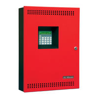
Mircom FA-300 Series Installation And Operation Manual (92 pages)
LCD Fire Alarm Control Panel
Brand:
Mircom
| Category:
Control Panel
| Size: 6.66 MB
Table of Contents
Table of Contents
3
1 Industry Canada and FCC Notice
9
Notice for All FA-300 Series Built-In Udacts Sold in Canada
9
2 Introduction
11
Overall Features
11
3 Conventions
12
Circuits
12
Zone
12
Events
12
Wiring Styles
12
4 System Components
13
Main Fire Control Panel
13
Figure 1 FA-300 LCD
13
Table 1 FA-300 LCD Series Comparison Chart
13
Relay Module: 12 Relays
14
Relay Modules: Six Relays
14
Polarity Reversal/City Tie
14
Remote Annunciator
14
Smart Relay Module
15
Input Class a Converter: Six Circuits
15
Output Class a Converter: Four Circuits
15
Output Class a Converter: Two Circuits
15
4.10 Active End-Of-Line Resistor
16
4.11 RAM-216 Remote Annunciator
16
4.12 Additional Fire Alarm System Accessories
16
5 Mechanical Installation
17
Installing the Enclosure
17
Figure 2 Enclosure Dimensions, Surface Mount
17
Figure 3 Enclosure Dimensions, Semi-Flush Mounting and Trim Ring
18
Figure 4 Flush Trim Detail (from Above)
18
BBX-1024DS and BBX-1024DSR Mechanical Installation
19
Figure 5 BBX-1024DS and BBX-1024DSR Installation Instructions and Dimensions
19
Installing the Adder Modules
20
Figure 6 Installation of Adder Modules for FA-301 LCD
20
Figure 7 Installation of Adder Modules for FA-300 LCD
21
6 Connections, DIP Switches, and Jumpers
22
Main Fire Alarm Board
22
Figure 8 Main Fire Alarm Board Connections, DIP Switches and Jumpers for FA-301 LCD
22
Figure 9 Main Fire Alarm Board Connections, DIP Switches and Jumpers for FA-300 LCD
23
ICAC-306 Input Class a Converter Adder Module
24
Figure 10 ICAC-306 Input Class a Converter Adder Module
24
OCAC-304/302 Output Class a Converter Adder Module
25
Relay Adder Modules (Models RM-312 and RM-306)
25
Figure 11 OCAC-304/302 Output Class a Converter Adder Module
25
Figure 12 RM-312 Twelve Relay Adder Module
26
Figure 13 RM-312/306 Relay Programming
26
RM-306 Six Relay Adder Module
27
Polarity Reversal and City Tie Module (Model PR-300)
27
Figure 14 RM-306 Six Relay Adder Module
27
Figure 15 Polarity Reversal and City Tie Module
27
7 Field Wiring
29
Main Fire Alarm Board Field Wiring
29
Figure 16 Initiating Circuit - Class B or Style B Wiring
29
Figure 17 Initiating Circuit- Class a or Style D Wiring
30
Figure 18 Indicating Circuit - Class B or Style y Wiring
30
Figure 19 Indicating Circuit -Class a or Style Z Wiring
31
Figure 20 Four-Wire Smoke Detector Wiring
31
Relay Adder Module Wiring
32
Figure 21 Dialer Wiring
32
Figure 22 Relay Per Zone (RM-312) Terminal Connection
32
Figure 23 Relay Per Zone (RM-306) Terminal Connection
33
Connecting to a 3G4010CF Interface Device
34
Figure 24 Connecting an FACP to a 3G4010CF Interface Device
34
Polarity Reversal and City Tie Module (PR-300) Wiring
35
Figure 25 Polarity Reversal and City Tie Module Terminal Connection
35
Power Supply Connection
36
Figure 26 Power Supply Connection
36
Table 2 Power Supply Ratings
36
Wiring Tables and Information
37
Table 3 Initiating Circuit Wiring
37
Table 4 Indicating Circuit Wiring
37
Supervised Auxiliary Power (Regulated)
38
Auxiliary Power (Unregulated)
38
8 Turning on the Panel
39
Before Connecting the Power
39
Connecting the Power
40
Figure 27 Battery Connections
40
Troubleshooting
41
Table 5 Troubleshooting
41
9 Indicators, Controls and Operations
42
Common Indicators
42
Figure 28 LCD Display and Control Buttons
42
Common Controls
43
Common Relays
44
Figure 29 Lamp Test
44
Circuit Types
45
Evacuation Codes
48
Fire Alarm Operation
48
Figure 30 Evacuation Codes
48
10 Supported Protocols and Devices
50
10.1 Synchronous Strobes
50
System Sensor's I3 Devices
50
Table 6 I3 Detector Leds
51
11 Configuration
52
Figure 31 FA-300 Main LCD Display
52
11.1 Accessing Configuration Mode
53
11.2 Command Menu
53
Figure 32 Enter Passcode
53
Panel Config (Command Menu)
55
Figure 34 FA-300 Config Menu
55
Figure 35 Feature Config Menu
55
Table 7 Feature Config Menu
56
Figure 33 Command Menu
59
Config. Info. (Command Menu)
62
Set Time (Command Menu)
63
Set Password (Command Menu)
64
View Eventlog (Command Menu)
64
Figure 36 the Event Log
64
Clear Eventlog (Command Menu)
65
Walk Test (Command Menu)
65
Figure 37 Walk Test Confirmation
65
Figure 38 Walk Test Zones
65
Figure 39 Walk Test Active
65
I3 Loop Test (Command Menu)
66
Figure 40 I3 Loop Test Confirmation
66
Figure 41 I3 Test Zones
66
Dialer Config (Command Menu)
67
Figure 42 I3 Test Not Ready
67
Figure 43 the Selected Zone Is Not I3 Type
67
Figure 44 Dialer Config Menu
67
Table 8 I3 Detector Leds While in Test Mode
67
Figure 45 Account Info Menu
68
Figure 46 Telephone Line Menu
69
Figure 47 Report Options Menu
70
Figure 48 Time Parameter
71
Test Dialer (Command Menu)
73
Figure 49 Dialer Test Menu
73
Bypass Det Ckt (Command Menu)
74
Bypass NAC Ckt (Command Menu)
75
Aux. Disc. (Command Menu)
75
Exit (Command Menu)
75
Figure 50 Detection Circuit Message
76
Figure 51 Indicating Circuit Message
76
Figure 52 AC Power Fail Message
77
Figure 53 Battery Trouble Message
77
Figure 54 Ground Fault Message
78
Figure 55 Remote Annunciator Message
78
Figure 56 Four-Wire Smoke Detector Supply Message
79
Figure 57 Supervised Auxiliary Supply Message
79
Figure 58 Module Missing Message
80
Figure 59 Module Trouble Message
80
12 Appendix A: Compatible Receivers
81
Table 9 Compatible Receivers
81
13 Appendix B: Reporting
82
13.1 Ademco Contact-ID
82
Table 10 Ademco Event Code
82
13.2 Security Industries Association SIA-DCS
83
Table 11 SIA Event Codes
83
14 Appendix C: Specifications
84
Table 12 FA-300 LCD Series Specifications
84
Table 13 FA-300 LCD System Modules and Annunciators
85
15 Appendix D: Power Supply and Battery Calculations
87
16 Warranty and Warning Information
89
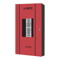
Mircom FA-300 Series Installation And Operation Manual (84 pages)
LED Fire Alarm Control Panel
Brand:
Mircom
| Category:
Control Panel
| Size: 1.5 MB
Table of Contents
Table of Contents
3
List of Figures and Tables
7
Industry Canada and FCC Notice
7
Introduction
8
Overall Features
8
Conventions
9
Circuits
9
Zone
9
Display Points
9
Wiring Styles
9
System Components
10
Main Fire Control Panel
10
Relay Module: 12 Relays
11
Relay Modules: Six Relays
11
Polarity Reversal/City Tie
11
Remote Annunciator
12
Smart Relay Module
12
Input Class a Converter: Six Circuits
13
Output Class a Converter: Four Circuits
13
Output Class a Converter: Two Circuits
13
Active End-Of-Line
13
RAM-216 Remote Annunciator
14
Additional Fire Alarm System Accessories
14
Mechanical Installation
15
Installing the Enclosure
15
Figure 1: Box Dimensions, Surface Mount
15
Figure 2: Box Dimensions, Semi-Flush Mounting and Trim Ring
16
Installing the Adder Modules
17
Figure 3: Installation of Adder Modules
17
Cable and Jumper Connections for Main Board and Adder Modules
18
Main Fire Alarm Board
18
Figure 4: Main Fire Alarm Board Cable Connector and Jumper Settings
18
ICAC-306 Input Class-A Converter Adder Module
19
Figure 5: ICAC-306 Input Class-A Converter Adder Module
19
Table 1: Connectors and Jumpers on the Main Fire Alarm Board
19
OCAC-304/302 Output Class-A Converter Adder Module
20
Relay Adder Modules (Models RM-312 and RM-306)
20
Figure 6: OCAC-304/302 Output Class-A Converter Adder Module
20
Figure 7: RM-312 Twelve Relay Adder Module
20
RM-306 Six Relay Adder Module
21
Figure 8: RM-312/306 Relay Programming
21
Figure 9: RM-306 Six Relay Adder Module
21
Polarity Reversal and City Tie Module (Model PR-300)
22
Figure 10: Polarity Reversal and City Tie Module
22
Table 2: PR-300 Jumper Settings
22
Field Wiring
23
Main Fire Alarm Board Field Wiring
23
Figure 11: Initiating Circuit - Class B or Style B Wiring
23
Figure 12: Initiating Circuit- Class a or Style D Wiring
24
Figure 13: Indicating Circuit - Class B or Style y Wiring
24
Figure 14: Indicating Circuit -Class a or Style Z Wiring
25
Figure 15: Four-Wire Smoke Detector Wiring
25
Relay Adder Module Wiring
26
Figure 16: Dialer Wiring
26
Figure 17: Relay Per Zone (RM-312) Terminal Connection
26
Figure 18: Relay Per Zone (RM-306) Terminal Connection
27
Polarity Reversal and City Tie Module (PR-300) Wiring
28
Figure 19: Polarity Reversal and City Tie Module Terminal Connection
28
Power Supply Connection
29
Figure 20: Power Supply Connection
29
Wiring Tables and Information
30
Four-Wire Smoke Power (Regulated)
30
Supervised Auxiliary Power (Regulated)
30
Table 3: Initiating Circuit Wiring
30
Table 4: Indicating Circuit Wiring
30
Auxiliary Power (Unregulated)
31
System Checkout
32
Before Turning the Power "ON
32
Power-Up Procedure
32
Troubleshooting
32
Indicators, Controls and Operations
33
Figure 21: LED Indicators and Control Buttons
33
Common Indicators
34
Alarm Circuit Indicators
36
Supervisory Circuit Indicators
36
Monitor Circuit Indicators
36
Trouble-Only Circuit Indicators
37
Signal Circuit Indicators
37
Common Controls
37
Circuit (Zone) Disconnect Buttons
38
Common Relays
39
Circuit Types
39
Evacuation Codes
41
Figure 22: Evacuation and Alert Codes
41
Single Stage Operation
42
Two-Stage Operation
42
Supported Protocols/Devices
44
Synchronous Strobes
44
System Sensor's I3 Devices
44
Configuration and CFG-300 LCD Service Tool
46
Figure 23: FA-300 Configuration
46
Entering the Passcode
47
Command Menu
47
FA-300 CONFIG (Command-Menu)
48
Config Info
57
Set Time (Command-Menu)
58
Change Password (Command-Menu)
59
View Event Log (Command-Menu)
59
Clear Event Log (Command-Menu)
60
Walk Test (Command-Menu)
61
I3 Loop Test (Command-Menu)
62
Dialer Config (Command-Menu)
63
Test Dialer (Command-Menu)
69
Exit (Command-Menu)
71
CFG-300 LCD Service Tool Operation
71
Appendix A: Compatible Receivers
75
Appendix B: Reporting
76
Ademco Contact-ID
76
Security Industries Association SIA-DCS
77
Appendix C: Specifications
78
Appendix D: Power Supply and Battery Calculations (Selection Guide)
79
Warranty & Warning Information
80
Warning Please Read Carefully
80
Limited Warranty
82
Warranty Procedure
82
Disclaimer of Warranties
82
Out of Warranty Repairs
83
Advertisement
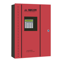
MirCom FA-300 Series Installation And Operation Manual (84 pages)
LCD Fire Alarm Control Panel
Brand:
MirCom
| Category:
Control Panel
| Size: 1.28 MB
Table of Contents
Cautions and Warnings
3
Table of Contents
5
Industry Canada and FCC Notice
9
Introduction
10
Overall Features
10
Conventions
11
Circuits
11
Zone
11
Events
11
Wiring Styles
11
System Components
12
Main Fire Control Panel
12
Relay Module: 12 Relays
13
Relay Modules: Six Relays
13
Polarity Reversal/City Tie
13
Remote Annunciator
14
Smart Relay Module
14
Input Class a Converter: Six Circuits
14
Output Class a Converter: Four Circuits
15
Output Class a Converter: Two Circuits
15
Active End-Of-Line
15
RAM-216 Remote Annunciator
15
Additional Fire Alarm System Accessories
15
Mechanical Installation
16
Installing the Enclosure
16
Figure 1: Box Dimensions, Surface Mount
16
Figure 2: FA-301-12DDR Box Dimensions, Semi-Flush Mounting with Trim Ring
17
Figure 2A: FA-300-6DDR/6DR Box Dimensions, Mounting and Trim Ring
18
Installing the Adder Modules
19
Figure 3: Installation of Adder Modules for FA-301 LCD Panels
19
Figure 4: Installation of Adder Modules for FA-300 LCD Panels
20
DIP Switch and Jumper Selections for Main Board and Adder Modules
21
Main Fire Alarm Board
21
Figure 5: Main Fire Alarm Board DIP Switch and Jumper Settings for FA-301 LCD Panels
21
Figure 6: Main Fire Alarm Board DIP Switch and Jumper Settings for FA-300 LCD Panels
22
Table 1: Connectors and Jumpers on the Main Fire Alarm Board
22
ICAC-306 Input Class-A Converter Adder Module
23
Figure 7: ICAC-306 Input Class-A Converter Adder Module
23
OCAC-304/302 Output Class-A Converter Adder Module
24
Relay Adder Modules (Models RM-312 and RM-306)
24
Figure 8: OCAC-304/302 Output Class-A Converter Adder Module
24
Figure 9: RM-312 Twelve Relay Adder Module
24
RM-306 Six Relay Adder Module
25
Figure 10: RM-312/306 Relay Programming
25
Figure 11: RM-306 Six Relay Adder Module
25
Polarity Reversal and City Tie Module (Model PR-300)
26
Figure 12: Polarity Reversal and City Tie Module
26
Table 2: PR-300 Jumper Settings
26
Field Wiring
27
Main Fire Alarm Board Field Wiring
27
Figure 13: Initiating Circuit - Class B or Style B Wiring
27
Figure 14: Initiating Circuit- Class a or Style D Wiring
28
Figure 15: Indicating Circuit - Class B or Style y Wiring
28
Figure 16: Indicating Circuit - Class a or Style Z Wiring
29
Figure 17: Four-Wire Smoke Detector Wiring
29
Figure 18: Dialer Wiring
30
Relay Adder Module Wiring
31
Figure 19: Relay Per Zone (RM-312) Terminal Connection
31
Figure 20: Relay Per Zone (RM-306) Terminal Connection
31
Polarity Reversal and City Tie Module (PR-300) Wiring
32
Power Supply Connection
32
Figure 21: Polarity Reversal and City Tie Module Terminal Connection
32
Wiring Tables and Information
33
Figure 22: Power Supply Connection
33
Table 3: Initiating Circuit Wiring
33
Four-Wire Smoke Power (Regulated)
34
Supervised Auxiliary Power (Regulated)
34
Auxiliary Power (Unregulated)
34
Table 4: Indicating Circuit Wiring
34
System Checkout
35
Before Turning the Power "ON
35
Power-Up Procedure
35
Troubleshooting
35
Indicators, Controls and Operations
36
Figure 23: LCD Display and Control Buttons
36
Common Indicators
37
Common Controls
37
Common Relays
38
Circuit Types
39
Evacuation Codes
40
Figure 24: Evacuation Codes
40
Fire Alarm Operation
41
Supported Protocols/Devices
42
Synchronous Strobes
42
System Sensor's I3 Devices
42
Configuration
44
Entering the Passcode
44
Figure 25: FA-300 Configuration
44
Command Menu
45
FA-300 CONFIG (Command-Menu)
46
Config Info (Command-Menu)
54
Set Time (Command-Menu)
55
Set Password (Command-Menu)
56
View Event Log (Command-Menu)
56
Clear Event Log (Command-Menu)
57
Walk Test (Command-Menu)
58
I3 Loop Test (Command-Menu)
59
Dialer Config (Command-Menu)
60
Test Dialer (Command-Menu)
65
Bypass Det Ckt (Command-Menu)
67
Bypass NAC Ckt (Command-Menu)
67
Aux. Disconnect (Command-Menu)
67
Exit (Command-Menu)
68
Battery Trouble
69
Ground Fault
69
Appendix A: Compatible Receivers
73
Appendix B: Reporting
74
Ademco Contact-ID
74
Security Industries Association SIA-DCS
75
Appendix C: Specifications
76
Appendix D: Power Supply and Battery Calculations (Selection Guide)
77
Warranty
78
Limited Warranty
80
Warranty Procedure
80
Disclaimer of Warranties
80
Out of Warranty Repairs
81
Mircom FA-300 Series Installation And Operation Manual (20 pages)
LCD Fire Alarm Control Panel
Brand:
Mircom
| Category:
Control Panel
| Size: 1.16 MB
Table of Contents
Table of Contents
3
1 Introduction
5
About this Manual
5
Technical Support
5
2 Main Display
6
Figure 1 Main Display
6
3 The Buzzer and LED Indicators
7
Buzzer
7
On LED
7
Alarm LED
7
Supervisory LED
7
Trouble LED
7
CPU Fail LED
7
Figure 2 LED Indicators
7
4 Main Display Buttons
8
System Reset
8
Signal Silence
8
Fire Drill
8
Lamp Test
8
Buzzer Silence
8
The up and down Arrow Buttons
8
Info
9
ENTER, MENU, and CANCEL
9
5 Disconnecting and Reconnecting a Circuit (Zone)
10
To Disconnect (Bypass) a Circuit
10
To Reconnect (Unbypass) a Circuit
11
6 Understanding On-Screen Messages
12
Example 1 (Detection Circuit)
12
Example 2 (Indicating Circuit)
12
Figure 3 Verified Alarm Example
12
Common Messages
13
AC Power Fail
13
Battery Trouble
13
Figure 4 Silenceable Signal Example
13
Figure 5 AC Power Fail
13
Ground Fault
14
RAU Num Mismatch
14
Figure 6 Battery Trouble
14
Figure 7 Ground Fault
14
4Wire Pwr. Supply
15
Supervised Aux-Supply
15
Figure 8 RAU Num Mismatch
15
Figure 9 4Wire Pwr. Supply
15
City Tie Polarity Reversal - PR-300/Relay Module
16
Figure 10 Aux. Power Supply
16
Figure 11 Ctytie/Rm312 Missing
16
Figure 12 City Tie Trouble
17
7 Glossary
18
Mircom FA-300 Series User Manual (20 pages)
LED Fire Alarm Control Panel
Brand:
Mircom
| Category:
Control Panel
| Size: 0.94 MB
Table of Contents
Table of Contents
3
1 Introduction
5
About this Manual
5
Technical Support
5
2 Main Display
6
Paper Labels for Buttons and Indicators
7
3 The Buzzer and LED Indicators
8
Common LED Indicators
8
Indicating Circuit Indicators
10
4 Main Display Buttons
14
SYSTEM RESET Button
14
SIGNAL SILENCE Button
14
FIRE DRILL Button
14
AUTOMATIC ALARM SIGNAL CANCEL Button (or ALM/SUP/TBL/BLDG AUDIBLE SIL Button for Single Stage System)
14
GENERAL ALARM Button
14
AUXILIARY DISCONNECT Button
15
LAMP TEST Button
15
ALM/SUP/TBL/BLDG AUDIBLE SIL Button (or MENU for Single Stage Systems)
15
5 Circuit (Zone) Disconnect Buttons
16
6 Glossary
17
Mircom FA-300 Series User Manual (16 pages)
LED Fire Alarm Control Panel
Brand:
Mircom
| Category:
Control Panel
| Size: 0.3 MB
Table of Contents
Table of Contents
3
Contents
4
Introduction
5
About this Manual
5
Technical Support
5
Main Display
6
The Buzzer and LED Indicators
7
Common LED Indicators
7
Alarm Circuit Indicators
9
Supervisory Circuit Indicators
9
Monitor Circuit Indicators
10
Trouble-Only Circuit Indicators
10
Signal Circuit Indicators
10
Main Display Buttons
11
Circuit (Zone) Disconnect Buttons
12
Glossary
13
Advertisement
Related Products
Mircom FA-300-6L Series
Mircom FA-300-6LDR
Mircom FA-300-6LDW
Mircom FA-300-6DR
Mircom FA-300-6DDR-CG
Mircom FA-301-8LDW
Mircom FA-1000 SERIES
Mircom FA-101U
Mircom FA-1008KA
Mircom FA-204E
MirCom Categories
Control Panel
Intercom System
Fire Alarms
Controller
Security System
More MirCom Manuals
Login
Sign In
OR
Sign in with Facebook
Sign in with Google
Upload manual
Upload from disk
Upload from URL