Mircom FA-300 Series Installation And Operation Manual
Led fire alarm control panel
Hide thumbs
Also See for FA-300 Series:
- Installation and operation manual (92 pages) ,
- User manual (20 pages) ,
- User manual (16 pages)
Table of Contents
Advertisement
Quick Links
See also:
User Manual
Advertisement
Table of Contents

Related Manuals for Mircom FA-300 Series


Summary of Contents for Mircom FA-300 Series
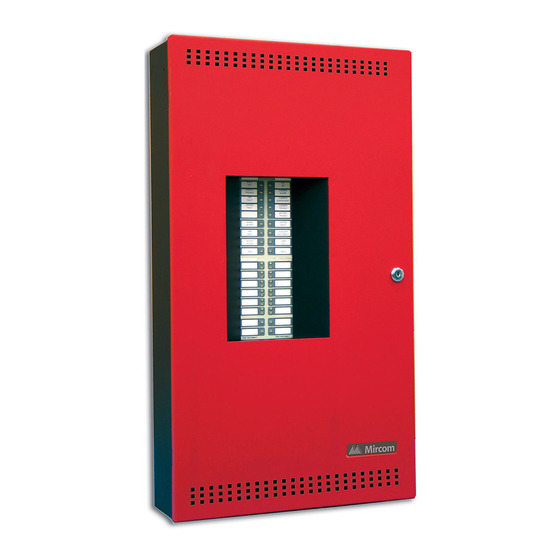
- Page 1 FA-300 Series LED Fire Alarm Control Panel LT-905 Rev. 11.4 Installation and Operation Manual March 2018...
-
Page 3: Table Of Contents
Table of Contents Industry Canada and FCC Notice Notice for all FA-300 Series Built-In UDACTs Sold in Canada ........Industry Canada Notice ....................Notice for all FA-300 Series Built-in UDACTs Sold in the U.S.A........Introduction Overall Features ......................Conventions Circuits ........................... - Page 4 Table of Contents ICAC-306 Input Class-A Converter Adder Module ............OCAC-304/302 Output Class-A Converter Adder Module ..........Relay Adder Modules ..................... Polarity Reversal and City Tie Module (Model PR-300) ..........Field wiring Main Fire Alarm Board Field Wiring ................Relay Adder Module Wiring ..................Connecting to a 3G4010 Interface Device for Canada ..........
- Page 5 Table of Contents 11.0 Configuration with the CFG-300 LCD Service Tool 11.1 Accessing Configuration Mode ..................11.2 Command Menu ......................11.3 1. FA-300 CONFIG (Command-Menu) ................11.4 2. Config Info (Command-Menu ..................11.5 3. Set Time (Command-Menu) ..................11.6 4. Change password (Command-Menu) ................ 11.7 5.
- Page 6 List of Figures Figure 1 FA-300 LED Series ......................Figure 2 Box dimensions, surface mount ..................Figure 3 Box dimensions, semi-flush mounting and trim ring ............Figure 4 Flush trim detail (from above) ..................Figure 5 BBX-1024DS and BBX-1024DSR Installation Instructions and Dimensions ....Figure 6 Installation of Adder Modules ..................
- Page 7 List of Figures Figure 44 Logs cleared ........................Figure 45 Walk test confirmation ....................Figure 46 Walk test zones ......................Figure 47 Walk test active ......................Figure 48 i3 loop test confirmation ....................Figure 49 i3 test zones ........................Figure 50 i3 test not ready ......................Figure 51 The selected zone is not i3 type ..................
- Page 8 List of Tables Table 1 FA-300 LED Series Comparison Chart ................Table 2 Power Supply Ratings ....................Table 3 Initiating Circuit Wiring ....................Table 4 Indicating Circuit Wiring ....................Table 5 RS-485 Wiring to Annunciators and other Devices ............Table 6 Alarm Circuit Indicators ....................
-
Page 9: Industry Canada And Fcc Notice
Industry Canada and FCC Notice Notice for all FA-300 Series Built-In UDACTs Sold in Canada Mircom's FA-300 SERIES BUILT-IN UDACT Communicator described in this manual is listed by Underwriters Laboratories Canada (ULC) for use in slave application in conjunction with a... - Page 10 Communicator, they should be performed by Mircom Technologies Ltd. or an authorized representative of Mircom Technologies Ltd. For information contact Mircom Technologies Ltd. at the address and phone numbers shown on the back page of this document.
-
Page 11: Introduction
Introduction Mircom's FA-300 Series Fire Alarm Control Panel is a Digital Signal Processor (DSP)-based fire panel. The FA-300 provides a maximum of 12 supervised Class B or A (Style B or D) Initiating circuits, and maximum four supervised Class B or A (Style Y or Z) indicating circuits. -
Page 12: Conventions
Conventions Circuits Refers to an actual electrical interface for Initiating (Detection) and Indicating (Signal or NAC) or Relays. Zone Is a logical concept for a Fire Alarm Protected Area, and consists of at least one circuit. Often the terms zone and circuit are used interchangeably, but in this manual circuit refers only to a physical electrical loop. -
Page 13: System Components
Contain Common Alarm, Common Supervisory & Common Trouble Relays, Auxiliary • Alarm Relay (disconnectable), an RS-485 Interface for Remote Annunciators and a Resettable Four Wire Smoke Detector Power Supply. Used with Mircom BAT-12V12A (12 Amp-hour) batteries (two required). • Table 1 FA-300 LED Series Comparison Chart... -
Page 14: Relay Module: 12 Relays
A.C. ON ALARM SUPV TRBL CPU FAIL SYSTEM RESET RAM-300LCDW SIGNAL ENTER SILENCE painted box FIRE MENU DRILL BUZZER CANCEL SILENCE LAMP INFO TEST Remote Annunciator Module, LCD display, red Advanced Life Safety Solutions RAM-300LCDR FA-300 SERIES painted box Remote Annunciator... -
Page 15: Smart Relay Module
System Components Smart Relay Module Model Description Smart Relay Module (12 relays) with white enclosure SRM-312W Smart Relay Module (12 relays) with red enclosure Advanced Life Safety Solutions SRM-312R FR-320 SERIES REMOTE RELAY Input Class A converter: Six Circuits Model Description Input Class A converter Module (six circuits). -
Page 16: 4.10 Active End-Of-Line Resistors
System Components 4.10 Active End-of-Line Resistors The ELRX-300 are power-saving End-of-Line resistors that eliminate the need for an additional battery cabinet or larger batteries in order to meet the 60 hour standby requirement. Model Description Active end-of-line resistor without plate ELRX-300 BLACK Active end-of-line resistor with end-of-line red plate... -
Page 17: Mechanical Installation
Mechanical Installation Installing the Enclosure Install the FA-300 Series Fire Alarm Panel enclosure as shown below for the twelve-, eight-, and six-zone models. Mount enclosure surface mount using the four mounting holes, as shown and the screws provided. 11" Mounting Hole 1.5"... -
Page 18: Figure 3 Box Dimensions, Semi-Flush Mounting And Trim Ring
Mechanical Installation flush mount the backbox into the wall. Peel the adhesive cover from the trim ring and stick to the wall surface around the backbox, after wall is finished. 11" 1.5" PLACE FA-UNIV-TRB TRIM RING OVER BACKBOX 17" 20.5" 26"... -
Page 19: Bbx-1024Ds And Bbx-1024Dsr Mechanical Installation
Mechanical Installation BBX-1024DS and BBX-1024DSR Mechanical Installation The BBX-1024DS and BBX-1024DSR are suitable for flush or surface mounting, and have a built-in trim ring. 14.5” x 4.2” x 26” Dimensions of Enclosure (minus built in trim ring) 12” Distance between horizontal mounting screws 23.5”... -
Page 20: Installing The Adder Modules
Mechanical Installation Installing the Adder Modules FA-300 Series Fire Alarm panels come pre-assembled with all components and boards except for Adder Modules. Module installation locations are shown in Figure 6. Refer to Figure 7 on the next page for jumper and DIP switch settings and see 7.7 Wiring Tables and Information on page 36 for wiring specifications. -
Page 21: Cable And Jumper Connections For Main Board And Adder Modules
Cable and Jumper Connections for Main Board and Adder Modules Main Fire Alarm Board For PC programming use UIMA interface module not UL-864 or ULC-S527 listed. Please refer to Document LT-929 for details Telephone line #1 Telephone line #2 For front panel programming use CFG -300 configuration tool not UL-864 or ULC-S527 listed. -
Page 22: Icac-306 Input Class-A Converter Adder Module
Cable and Jumper Connections for Main Board and Adder Modules 6.1.1 Connectors and Jumpers on the Main Fire Alarm Board Cable from P1 of the PR-300 Polarity Reversal and City Tie Module connects here. Otherwise not used. Cable from connector P1 of the RM-312 or RM-306 Relay Adder Module connects here. -
Page 23: Ocac-304/302 Output Class-A Converter Adder Module
Cable and Jumper Connections for Main Board and Adder Modules Board. From the ICAC-306 converter Initiating circuits are wired out to the devices from the positive and negative terminals marked DET OUT and the circuit return wires are brought back to the converter module to positive and negative terminals marked DET RET. -
Page 24: Figure 10 Rm-312 Twelve Relay Adder Module
Cable and Jumper Connections for Main Board and Adder Modules jumpers located below the relays are used to select either normally open contacts or normally closed contacts. Connect to P6 on the main fire alarm board INDIVIDUAL GREEN RELAY STATUS LEDs RELAY 1 RELAY 2 RELAY 4... -
Page 25: Polarity Reversal And City Tie Module (Model Pr-300)
Cable and Jumper Connections for Main Board and Adder Modules 6.4.3 RM-306 Six Relay Adder Module Cable from P1 of the RM-306 is connected to P6 on the Main Fire Alarm Board. The jumpers located above each relay on the RM-306 are used to configure the relays. The jumpers located below the relays are used to select either normally open contacts or normally closed contacts. - Page 26 Cable and Jumper Connections for Main Board and Adder Modules 6.5.1 PR-300 jumper settings Cable connects to P5 on the Main Board Not used. Jumper JW4 remains on board. P2 & JW4 The Alarm Transmit signal to the PR-300 can be programmed to turn OFF when signal silence is active.
-
Page 27: Field Wiring
Field wiring Main Fire Alarm Board Field Wiring Wire devices to the terminals as shown in the figures that follow. Refer to the Wiring Tables for wire gauges and to Appendix A for specifications. Caution: Do not exceed power supply ratings. 7.1.1 Initiating Circuit Wiring Class B Wiring diagrams for the initiating circuits are shown below. -
Page 28: Figure 15 Initiating Circuit- Class A Or Style D Wiring
Initiating circuit– Class A or Style D wiring 7.1.3 Indicating Circuit Wiring The FA-300 Series Fire Alarm supports Class B (Style Y) and Class A (Style Z) wiring for its indicating circuits. Each circuit is supervised by a 3.9K End-of-Line resistor. Each indicating circuit provides up to 1.7 A, 5 A maximum total if no auxiliaries are used. -
Page 29: Figure 16 Indicating Circuit - Class B Or Style Y Wiring
Field wiring FIRE ALARM MAIN BOARD STYLE Y WIRING INDICATING INDICATING CIRCUIT - 1 CIRCUIT #1 INDICATING STYLE Y CIRCUIT #2 WIRING INDICATING CIRCUIT - 2 BELL STROBE HORN 3.9K 1/2 WATT ELR Figure 16 Indicating circuit – Class B or Style Y wiring OCAC-304 CLASS A STYLE Z CONVERTER MODULE... -
Page 30: Figure 18 Four-Wire Smoke Detector Wiring
Field wiring 7.1.4 Four Wire Smoke Detector Wiring FIRE ALARM MAIN BOARD POWER RESETTABLE 4-WIRE SMOKE DETECTOR POWER SUPPLY 22VDC, 200mA MAX. CURRENT - 300mA MAX. RIPPLE VOL. 5mV (POWER LIMITED) DETECTION END OF LINE RELAY 4-WIRE DETECTION DEVICE LISTED S3403 MODEL A77-716B TO INITIATING MANUFACTURED BY... -
Page 31: Relay Adder Module Wiring
Field wiring Relay Adder Module Wiring Wire relays on the relay adder modules RM-312 and RM-306 as shown in Figures 19 and 20. RM-312 12 RELAY ADDER MODULE NORMALLY OPEN RELAY NORMALLY OPEN OR CONNECTION CIRCUIT #1 NORMALLY CLOSED NO/NC CONNECTION IS SELECTED BY JUMPER NORMALLY CLOSE... -
Page 32: Connecting To A 3G4010 Interface Device For Canada
Field wiring Connecting to a 3G4010 Interface Device for Canada A typical connection is shown in Figure 22. The PCS-100 Passive Communications Interface Board (sold separately) is required. For information on Compatible DACR Receivers see 12.0 Appendix A: Compatible Receivers on page 94. FA-300 - 3G4010 Connection - Typical Diagram To GSM/GPRS Telephone... -
Page 33: Connecting To A 3G4010Cf Interface Device Outside Canada
Field wiring Connecting to a 3G4010CF Interface Device outside Canada For information on Compatible Receivers see 12.0 Appendix A: Compatible Receivers on page 94. A typical connection is shown in Figure 23. The 3G4010CF is powered separately from the PCS-100 and requires 2 DSC RM-2 relays (sold separately). The PCS-100 Passive Communications Interface Board (sold separately) is also required. -
Page 34: Polarity Reversal And City Tie Module (Pr-300) Wiring
Field wiring Polarity Reversal and City Tie Module (PR-300) Wiring Wire PR-300 Polarity Reversal and City Tie Module (if used) as shown in Figure 24, below. See 12.0 Appendix A: Compatible Receivers on page 94 for module specifications. Power Limited cable type FPL, FPLR or FPLP must be used. For USA installation, the installer must use Atlantic Scientific (Tel: 407-725-8000), Model #24544 Protective Device, or similar UL-Listed QVRG secondary protector, as shown. -
Page 35: Power Supply Connection
Field wiring Power supply connection The power supply is part of the Main Chassis. The ratings are: Table 2 Power Supply Ratings Type Rating Electrical Input rating 120VAC, 60Hz, 3A\ 240 VAC, 50 Hz, 1.5A Power supply total current 6A maximum Battery fuse on Main 10A, slow blow micro fuse module... -
Page 36: Wiring Tables And Information
Field wiring Wiring Tables and Information Table 3 Initiating Circuit Wiring Wire gauge Maximum wiring run to last device Feet Meters 2990 4760 1450 7560 2300 12000 3600 19000 5800 30400 9200 Notes: For Class A the maximum wiring run to the last device is divided by two. Maximum loop resistance should not exceed 100 ohms. -
Page 37: Four-Wire Smoke Power
Field wiring Table 5 RS-485 Wiring to Annunciators and other Devices Wire gauge Maximum wiring run to last device Feet Meters 2000 609.6 4000 1219.2 8000 2438.4 Notes: Use twisted shielded pair, 300mA power limited. Maximum 40 ohm loop resistance Four-Wire Smoke Power 4-wire smoke power is provided for 4-wire smoke detectors. -
Page 38: Turning On The Panel
Turning on the Panel Before Connecting the Power 1. To prevent sparking, do not connect the batteries. Connect the batteries after powering the system from the main AC supply. 2. Check that all modules are installed in the proper location with the proper connections. 3. -
Page 39: Figure 26 Battery Connections
Turning on the Panel J W 1 red red B ATTE RY SEC. TX yellow 240 VAC 50Hz 120 VAC 60Hz green Battery Battery NOTE: TO PREVENT SPARKING, CONNECT BATTERIES AFTER THE SYSTEM MAIN A.C. POWER IS TURNED ON Figure 26 Battery connections All indicators should be off except for the green A.C. -
Page 40: Troubleshooting
Turning on the Panel Troubleshooting Symptoms Possible Cause Normally when a circuit trouble occurs, its designated trouble indicator is illuminated, as well as the COMMON TROUBLE indicator and trouble buzzer. To correct the fault, Circuit check for open wiring on that particular circuit loop, and check that the circuit is not Trouble disconnected or bypassed. -
Page 41: Indicators, Controls And Operations
Indicators, Controls and Operations Refer to Figure 27 below for LED Indicator and Control Button locations. W ALK A.C. TE S T RE MO TE CO MMO N TRO UBLE ALARM CO MMO N CP U FAULT S UP V GRO UND CO MMO N FAULT... -
Page 42: Common Indicators
• Note that each display is supplied with laser printer printable paper labels for sliding into the plastic label template on the panel. For the Main Display, the paper label is Mircom# NP-2005; this includes English and French versions. There are different labels for two stage operation. - Page 43 Indicators, Controls and Operations 9.1.4 COMMON SUPERVISORY LED The amber COMMON SUPERVISORY LED illuminates steadily when there is a Supervisory Alarm in the panel caused by any Latching or Non-Latching Supervisory Circuit. The LED is turned of when all Non-Latching Supervisory Circuits are restored and there are no active Latching Supervisory Circuits.
- Page 44 Indicators, Controls and Operations 9.1.10 WALK TEST LED The amber WALK TEST LED illuminates steadily to indicate that the panel is in Walk Test Mode. If the panel is left in this mode for over an hour with no operator activity, the panel returns to normal and the WALK TEST LED turns off.
-
Page 45: Indicating Circuit Indicators
Indicators, Controls and Operations Indicating Circuit Indicators The panel has 1 indicator for each of the 12 initiating circuits (shown in Figure 27). Each indicator has a button and 2 LEDs, shown in Figure 28. Circuit Circuit Status LED Disconnect Z O NE -1 Circuit Trouble LED DIS CO NNE CT... -
Page 46: Table 8 Property And Building Safety Indicators
Indicators, Controls and Operations Table 7 Supervisory Circuit Indicators (Continued) Activated circuit reconnected (when you Fast flash rate (red) for 5 press the Disconnect button a second seconds to indicate a time) pending alarm Event Circuit Trouble LED Configuration Flashes at the trouble rate Open circuit (Class B) (amber) Flashes at the trouble rate... -
Page 47: Signal Circuit Indicators
Indicators, Controls and Operations 9.2.4 Trouble-only Circuit Indicators This operation applies to initiating circuits configured as Trouble-only Circuits. The following table summarizes the indications in response to different events. Table 9 Trouble-Only Circuit Indicators Event Circuit Trouble LED Configuration Flashes at the trouble rate Open circuit (Class B) (amber) Flashes at the trouble rate... - Page 48 Indicators, Controls and Operations Turns off all Indicating Circuits • Turns off SIGNAL SILENCE, AUTOMATIC ALARM SIGNAL CANCEL (Acknowledge), • and GENERAL ALARM Indicators Turns off Fire Drill • Stops and resets all timers • Processes inputs as new events •...
-
Page 49: Circuit (Zone) Disconnect Buttons
Indicators, Controls and Operations trouble message and the buzzer to flash at the trouble flash rate. Pressing the AUXILIARY DISCONNECT button causes the system to return to normal. 9.4.7 LAMP TEST Button Press the LAMP TEST button to cause all front panel LEDs (except the CPU FAULT LED) to illuminate steadily and turn the buzzer on. -
Page 50: Common Relays
Indicators, Controls and Operations Disconnect buttons are also used during Walk Test as described in 11.9 7. Walk Test (Command-Menu) on page 76. Common Relays 9.6.1 Auxiliary Alarm Relay The Auxiliary Alarm Relay functions the same way as the Common Alarm Relay in every respect except that it can be disconnected by Auxiliary Disconnect with or without other correlated relays if it is programmed to do so (see Table 14 on page 63). - Page 51 Indicators, Controls and Operations 9.7.3 Verified Alarm Verified Alarms are verified by a reset and timing procedure, and may include smoke detectors, heat detectors or pull stations. Activation of pull stations or heat detectors results in an alarm condition in the Fire Alarm Control Panel within four seconds. Smoke detectors are verified for a real alarm within 60 seconds, depending upon the startup time of the devices being used.
-
Page 52: Indicating (Signal) Circuit Types
Indicators, Controls and Operations Annunciator General Alarm button. In a single stage system, these inputs act the same as Non-Verified Alarms; however, if Correlations are enabled, General Alarm Initiating Circuits are correlated to ALL indicating circuits. 9.7.9 Property and building safety This is a supervised general-purpose non-latching input used mainly for correlating to a relay circuit associated with property and building safety. -
Page 53: 9.10 Single Stage Operation
Indicators, Controls and Operations March Code 0.5 second on, 0.5 second off California Code 5 seconds on, 10 seconds off 9.9.2 Two-step codes Alert Code 0.5 second on, 2.5 seconds off General Alarm Evacuation Code as selected from above. Continuous 0.5s 1.5s Temporal Code... -
Page 54: 9.11 Two-Stage Operation
Indicators, Controls and Operations If Signals have been silenced as a result of the Signal Silence button or the Auto Signal • Silence Timer, Signals are resounded as they were before Signal Silence, the Signal Silence Indicator is turned off, and the Auto Signal Silence Timer, if configured, is restarted. - Page 55 Indicators, Controls and Operations If the panel is not already in General Alarm, additional non-Disconnected Signals • programmed to the new input are activated with the Alert Code (see 9.8 Indicating (Signal) Circuit Types on page 52). If the panel is not already in General Alarm and if the AUTOMATIC ALARM SIGNAL •...
-
Page 56: Supported Protocols/Devices
10.0 Supported Protocols/Devices 10.1 Synchronous Strobes A separate compatibility list is available for different supported models. Strobes can be configured as normal (not synchronized or any of the above; see 11.0 Configuration with the CFG-300 LCD Service Tool on page 59). Any selection made is system- wide (that is, whatever is selected applies to all the circuits in the system, configured as strobes). -
Page 57: Figure 31 Open Circuit Trouble
Supported Protocols/Devices Open circuit trouble • Communication trouble • Out of sensitivity: defective or dirty device • Freeze trouble • 10.2.2 Open Circuit Trouble If the loop is broken the panel shows open loop trouble. The panel can still communicate with the devices depending upon where the open occurs. -
Page 58: Figure 35 Freeze Trouble
Supported Protocols/Devices 10.2.6 Freeze Trouble If the device has detected a freeze condition, (e.g. the temperature is below 41F / 5 C) then the panel displays a freeze trouble. Only model 2WT-B is capable of thermal detection; model 2W-B does not indicate any freeze trouble. Z o n e - 1 F r e e z e T r b . -
Page 59: Configuration With The Cfg-300 Lcd Service Tool
11.0 Configuration with the CFG-300 LCD Service Tool Table 12 Settings permitted in CAN/ULCS527 NOTICE TO USERS, INSTALLERS, AUTHORITIES HAVING JURISDICTION, AND OTHER INVOLVED PARTIES This product incorporates field-programmable software. In order for the product to comply with the requirements in CAN/ULCS527, Standard for Control Units for Fire Alarm Systems, certain programming features or options must be limited to specific values or not used at all as indicated below. -
Page 60: 11.1 Accessing Configuration Mode
Configuration with the CFG-300 LCD Service Tool Figure 36 shows the function of the buttons on the front panel display. W ALK A.C. TE S T RE MO TE CO MMO N TRO UBLE ALARM CO MMO N CP U FAULT S UP V GRO UND CO MMO N... -
Page 61: 11.2 Command Menu
Configuration with the CFG-300 LCD Service Tool 5. If the passcode is wrong, the system prompts you to re-enter the passcode. After three tries the system takes you back to the normal message display. Enter passcode Figure 37 Enter passcode 11.2 Command Menu The command menu is shown in Figure 38. -
Page 62: Config (Command-Menu)
Configuration with the CFG-300 LCD Service Tool 2. Press ENTER to select an option. The corresponding menu appears. 3. Press the up and down arrow buttons to scroll through the menu. 4. Press the left or right arrow buttons to select or unselect an option (selected = X). Use the up and down arrows to scroll through the different options. -
Page 63: Figure 40 Feature Config Menu
Configuration with the CFG-300 LCD Service Tool Select Features to access the Feature Config menu shown in Figure 40. - Feature Config - 1 Man. Sig. Sil. 2 Fire Drill 3 Opt. Ckt. Corr 4 Wtr/Sprk. Retd 5 Aux Disc Prog 6 Sig-Sil Inh Tm 7 Aux Dis, Alm&Sup 8 Auto Sil. - Page 64 Configuration with the CFG-300 LCD Service Tool Table 14 Feature Config menu Name in the FA-300 Feature Default Description Configuration Utility Command Menu/FA-300 Config/Features/ If enabled, the programmed 3.Output Circuit Correlation correlations (see 11.3.5 Command Menu/FA-300 Config-- O p t . C k t . C o r r . >Correlation on page 70) are [X] DISABLE->Default Signal correlations...
- Page 65 Configuration with the CFG-300 LCD Service Tool Table 14 Feature Config menu Name in the FA-300 Feature Default Description Configuration Utility Command Menu/FA-300 Config/Features/ If enabled, the Common Alarm 7. AUXILIARY DISCONNECT Relay and the Common disconnects Alarm Relay and Supervisory Relay, in addition to Supervisory Relay the Auxiliary Alarm Relay, are...
- Page 66 The selection is [X] NORMAL ->Default S t r o b e T y p e system-wide and applies to all [ ] MIRCOM [ X ] N O R M A L indicating circuits configured as Strobe [ ] FARADY strobes.
- Page 67 Configuration with the CFG-300 LCD Service Tool Table 14 Feature Config menu Name in the FA-300 Feature Default Description Configuration Utility Command Menu/FA-300 Config/Features/ [X] DISABLE->Default 18. Auto General Alarm Timer [ ] 5 Min This function is used for two- [ ] 10 Min stage systems only.
- Page 68 Configuration with the CFG-300 LCD Service Tool Refer to 11.2.1 Using the Keypad to Program the FA-300 on page 61 for detailed Note: instructions on making menu selections. 11.3.2 Command Menu/FA-300 Config-->Inp Zone I n i t i a t i n g Z o n e 1 Z o n e - 1 2 Z o n e - 2 1 2 Z o n e 1 2...
- Page 69 Configuration with the CFG-300 LCD Service Tool Refer to 11.2.1 Using the Keypad to Program the FA-300 on page 61 for detailed Note: instructions on making menu selections. 11.3.4 Command Menu/FA-300 Config-->Opt Zone I n d i c a t i n g Z o n e 1 N A C - 1 2 N A C - 2 3 N A C - 3...
- Page 70 Configuration with the CFG-300 LCD Service Tool Refer to 11.2.1 Using the Keypad to Program the FA-300 on page 61 for detailed Note: instructions on making menu selections. 11.3.5 Command Menu/FA-300 Config-->Correlation Command Menu/FA-300 Config/Correlation 1.Correlation Z o n e - 1 C o r r . [ X ] N A C - 1 Use this menu to correlate [X] NAC-1 ->Default...
- Page 71 Configuration with the CFG-300 LCD Service Tool Command Menu/FA-300 Config/Ipt. Zone Label 1.Initiating zone label [Zone-1 ]->Default Zone-1 Label [Zone-12 ]->Default Zone-1 BYPASS SWITCH TRANSLATION KEY SEQ 1 2 3 4 KEY SEQ 1 2 3 4 -------------------------------------- Zone-1 0 Q Z Zone-2 1 Zone-3 2 A B C...
-
Page 72: Config Info
Configuration with the CFG-300 LCD Service Tool Use the buttons described below for entering messages. These buttons are alternate functions of bypass switches and are physically located in the same position as described below. Command Menu/FA-300 Config/Opt. Zone Label 1.Indicating zone label [NAC-1 ]->Default NAC-1 Label... -
Page 73: Set Time (Command-Menu)
Configuration with the CFG-300 LCD Service Tool Configuration type shows how the panel was configured. Configuration type: Factory default means the panel has not been configured; it is as it came from the factory. Factory default Front Panel means it was configured at the panel. Serial Port means the configuration was done from a computer through the serial port. - Page 74 Configuration with the CFG-300 LCD Service Tool Use this menu to set the Command Menu/Set Time time and date. Use the left 2. Set time and date and right arrow buttons to move the cursor to the desired location in the H H : M M W K D Y Y Y Y - M M - D D display and use the up and 0 0 : 0 0 M O N 2 0 0 0 - 0 1 - 0 1...
-
Page 75: Change Password (Command-Menu)
Configuration with the CFG-300 LCD Service Tool 11.6 4. Change password (Command-Menu) Refer to 11.2.1 Using the Keypad to Program the FA-300 on page 61 for detailed Note: instructions on making menu selections. Enter new passcode Re-enter passcode Use this menu to change If the passcode does not match, the the passcode. -
Page 76: Clear Event Log (Command-Menu)
Configuration with the CFG-300 LCD Service Tool 11.8 6. Clear Event Log (Command-Menu) Refer to 11.2.1 Using the Keypad to Program the FA-300 on page 61 for detailed Note: instructions on making menu selections. Use this menu to clear alarm logs, event logs, or both. -Select Log- 1 Alarm Log 2 General Log... -
Page 77: Figure 46 Walk Test Zones
Configuration with the CFG-300 LCD Service Tool Press the ENTER button to activate the walk test and the CANCEL button to cancel the walk test. The next screen allows zones to be selected for walk test. Use the up and down arrow buttons to scroll through the zones and use the left and right arrow buttons to select a zone. -
Page 78: I3 Loop Test (Command-Menu)
Configuration with the CFG-300 LCD Service Tool 11.10 8. i Loop Test (Command-Menu) Refer to 11.2.1 Using the Keypad to Program the FA-300 on page 61 for detailed Note: instructions on making menu selections. The i maintenance test is designed to test the devices on i zone. -
Page 79: Dialer Config (Command-Menu)
Configuration with the CFG-300 LCD Service Tool make sure all the devices are working properly. The following table lists the status of the devices while in walk test. Table 15 i3 Detector Statuses Green LED Red LED Detector Condition Proper operation Double blink every 5 sec Out of sensitivity Double blink every 5 sec... - Page 80 Configuration with the CFG-300 LCD Service Tool 11.11.1 Command Menu/Dialer Config-->Account Info - A c c o u n t I n f o - 1 A c c o u n t # 1 I D 2 A c c o u n t # 1 T e l 3 A c c n t # 1 F o r m a t 4 A c c o u n t # 2 I D 5 A c c o u n t # 2 T e l...
- Page 81 Configuration with the CFG-300 LCD Service Tool Command Menu/Dialer Config/Account Info 3.Account#1 Reporting Format [X] CONTACT ID-Default Set the reporting format that is recognized or preferred A C C N T # 1 F o r m a t : [ ] SIA 300 Baud by the monitoring station.
- Page 82 Configuration with the CFG-300 LCD Service Tool Refer to 11.2.1 Using the Keypad to Program the FA-300 on page 61 for detailed Note: instructions on making menu selections. 11.11.2 Command Menu/Dialer Config-->Telephone Line - T e l e p h o n e L i n e - 1 L i n e 1 D i a l t y p e 2 L i n e 2 D i a l t y p e 3 L i n e 1 D i a l t o n e...
- Page 83 Configuration with the CFG-300 LCD Service Tool Refer to 11.2.1 Using the Keypad to Program the FA-300 on page 61 for detailed Note: instructions on making menu selections. 11.11.3 Command Menu/Dialer Config-->Report Options - Report Options - 1 Alarm Prio. 2 Trouble Prio.
- Page 84 Configuration with the CFG-300 LCD Service Tool Command Menu/Dialer-Config/Report Options 5.Fire Panel type Do not change this function; [X] FA-300 Panel->Default keep it as default. F i r e P a n e l T y p e : [ ] FA-1000 Panel For factory use only.
- Page 85 Configuration with the CFG-300 LCD Service Tool Command Menu/Dialer-Config/Time Parameter Use this menu to set the 2.Cellular report date test report date for the cell 0 ->Default phone setup. Set this menu Cellular Report Date to 0 if there is no test reporting for a cell phone, or if the phone line is a regular line.
- Page 86 Configuration with the CFG-300 LCD Service Tool 11.11.5 Auto Test Time and Cellular Report Date If the Cellular report date is set to 0, then the dialer alternates between Lines 1 and 2 when performing the automatic test. If the Cellular report date is not set to 0, then the automatic test is performed on Line 1 except on the Cellular report date, when it is performed on Line 2.
-
Page 87: Test Dialer (Command-Menu)
Configuration with the CFG-300 LCD Service Tool 11.11.7 Command Menu/Dialer Config-->Ring Detect Use this menu item to select the number of rings -Ring Detect Number - on which the panel’s [ ] Disabled [X]5 modem answers. The [ ] 1 default number of rings is [ ] 2 five. -
Page 88: Exit (Command-Menu)
Configuration with the CFG-300 LCD Service Tool Failed: No Dialtone This message may indicate a noisy telephone line. Dialing Receiver Now The dial tone was received and telephone number dialing is in process. No DTMF tone This message indicates that the dialer failed to send a DTMF tone. -
Page 89: 11.15 Zone Messages
Configuration with the CFG-300 LCD Service Tool 11.15 Zone messages Point annunciation is indicated on the LCD display. There are no separate queues for TROUBLE, ALARM, SUPERVISORY and BUILDING; instead there is only one queue that indicates all the events. The respective TROUBLE, ALARM, SUPERVISORY and BUILDING LEDs flash if at least one of the given types is in the queue. -
Page 90: 11.16 Ac Power Fail
Configuration with the CFG-300 LCD Service Tool 11.16 AC Power Fail The AC power fail trouble is generated when the power drops below the UL specified value. The trouble is restored when the power returns to the normal value. T ro u b le c o d e T ro u b le In fo T ro u b le T yp e A C P o w e r F a i l... -
Page 91: 11.18 Ground Fault
Configuration with the CFG-300 LCD Service Tool 11.18 Ground Fault T ro u b le c o d e T ro u b le In fo T ro u b le T yp e G r o u n d F a u l t T r b : 0 x 0 3 I n f o : 0 x 0 0 0 1 "IN F O "... -
Page 92: 11.21 Supervised Aux. Supply
Configuration with the CFG-300 LCD Service Tool T ro u b le co d e T ro u b le In fo T ro u b le T yp e 4 W i r e P w r . S u p p l y T r b : 0 x 0 3 I n f o : 0 x 0 0 0 1 "I N F O "... -
Page 93: Figure 61 City Tie Module Missing
Configuration with the CFG-300 LCD Service Tool T ro u b le co d e T ro u b le In fo T ro u b le T yp e C t y T i e / R M x x x m i s s i n g T r b : 0 x 0 3 I n f o : 0 x 0 0 0 1 "IN F O "... -
Page 94: Appendix A: Compatible Receivers
12.0 Appendix A: Compatible Receivers The dialers that are built into select models of the FA-300 Series Fire Alarm Control Panels are compatible with the following Digital Alarm Communicator Receivers (DACR): DACR Receiver Model Protocols SurGard MLR2 Multi-Line Receiver (ULC, ULI approved) -
Page 95: Appendix B: Reporting
13.0 Appendix B: Reporting 13.1 Ademco Contact-ID 13.1.1 FA-300 Event Codes Event Description Event Family Qualifier Code Group # Contact # Phone Line #1 trouble detected Trouble New event 1 351 Phone Line #2 trouble detected Trouble New event 1 352 Phone Line #1 trouble restored Trouble Restore... -
Page 96: 13.2 Security Industries Association Sia-Dcs
Appendix B: Reporting 13.2 Security Industries Association SIA-DCS SIA protocol does not define indicating zone troubles, but lists it as Untyped Zone Trouble/ Restore. 13.2.1 FA-300 Event Codes Event Description Event Family Qualifier Event Parameter Code Phone Line #1 trouble detected Trouble New event Phone Line #2 trouble detected... -
Page 97: Appendix C: Specifications
14.0 Appendix C: Specifications Table 16 FA-300 LED Series Specifications FA-300 LED Fire Control Panel Chassis Digital Signal Processor based design. Fully configurable using front panel LCD General display with Password Access. 4 supervised Style Y (Class B) and Style Z (Class A) indicating circuits, Indicating (NAC) configured as strobes or audibles. -
Page 98: Table 17 Fa-300 Led System Modules And Annunciators
Battery Type 1.25 Amp Charging capability 10A on board (F1) slow blow micro fuse Protection FA-300 Series LED Version Fire Alarm Control Compliance System Model Panel Local, Auxiliary (using PR-300), Remote Protected System Type Premises Station (using PR-300 or FA-301-12LDR,... - Page 99 Appendix C: Specifications Table 17 FA-300 LED System Modules and Annunciators (Continued) FA-300 LED Series Modules and Annunciators Polarity Reversal and City Tie Module PR-300 power limited / 24VDC unfiltered / 250mA max City Tie /14Ohms trip coil power limited / 24VDC open / 12VDC at Polarity Reversal 3.5mA / 8.5mA max (shorted) 24VDC (normal) / -24VDC (supervisory) / 0V...
-
Page 100: Appendix D: Power Supply And Battery Calculations
([STANDBY (A) ______ ] X [(24 or 60 Hours) ___ ]) + ([ALARM (B) ______ ] X [Alarm in Hr.] _____) = (C) ______AH Total Alarm Current: Must be 6 Amperes or less for FA-300 Series. Indicating Circuits must not to exceed 5 Amperes. -
Page 101: Appendix E: Auxiliary Devices
16.0 Appendix E: Auxiliary Devices Model Description Remote Annunciator module, LCD display, white painted box RAM-300LCDW Remote Annunciator module, LCD display, red painted box RAM-300LCDR Smart Relay Module (12 relays) with white enclosure SRM-312W Smart Relay Module (12 relays) with red enclosure SRM-312R 8 Zone remote annunciator RAM-208... -
Page 102: Warranty And Warning Information
As the only individual in contact with system users, please bring each item in this warning to the attention of the users of this Mircom System. Failure to properly inform system end-users of the circumstances in which the system might fail may result in over-reliance upon the system. - Page 103 11. Battery Failure. If the Mircom System or any device connected to the system operates from batteries it is possible for the batteries to fail. Even if the batteries have not failed, they must be fully charged, in good condition, and installed correctly.
- Page 104 20. Integrated Products. Mircom System might not function as intended if it is connected to a non-Mircom product or to a Mircom product that is deemed non-compatible with a particular Mircom System.
- Page 105 Warranty and Warning Information...
- Page 106 CANADA - Main Office U.S.A © Mircom 2018 25 Interchange Way 4575 Witmer Industrial Estates Printed in Canada Subject to change without prior notice Vaughan, ON L4K 5W3 Niagara Falls, NY 14305 Tel: (905) 660-4655 Tel: (905) 660-4655 www.mircom.com (888) 660-4655...
Need help?
Do you have a question about the FA-300 Series and is the answer not in the manual?
Questions and answers