Mircom FA-300 Series Installation And Operation Manual
Lcd fire alarm control panel
Hide thumbs
Also See for FA-300 Series:
- Installation and operation manual (106 pages) ,
- User manual (20 pages) ,
- Installation and operation manual (84 pages)

Related Manuals for Mircom FA-300 Series


Summary of Contents for Mircom FA-300 Series
- Page 1 FA-300 Series LCD Fire Alarm Control Panel LT-906 Rev. 10.2 Installation and Operation Manual June 2017...
-
Page 3: Table Of Contents
Table of Contents Industry Canada and FCC Notice Notice for all FA-300 Series Built-In UDACTs Sold in Canada ........Introduction Overall Features ......................Conventions Circuits ........................... Zone ..........................Events ..........................Wiring Styles ........................System Components Main Fire Control Panel .................... - Page 4 Table of Contents RM-306 Six Relay Adder Module .................. Polarity Reversal and City Tie Module (Model PR-300) ..........Field wiring Main Fire Alarm Board Field Wiring ................Relay Adder Module Wiring ................... Connecting to a 3G4010CF Interface Device ..............Polarity Reversal and City Tie Module (PR-300) Wiring ..........Power supply connection ....................
- Page 5 Table of Contents 11.10 Walk Test (Command Menu) ..................11.11 I3 Loop Test (Command Menu) ..................11.12 Dialer Config (Command Menu) ..................11.13 Test Dialer (Command Menu) ..................11.14 Bypass Det Ckt (Command Menu) ................11.15 Bypass NAC Ckt (Command Menu) ................11.16 Aux.
- Page 6 List of Figures Figure 1 FA-300 LCD ........................Figure 2 Enclosure dimensions, surface mount ................Figure 3 Enclosure dimensions, semi-flush mounting and trim ring ..........Figure 4 Flush trim detail (from above) ..................Figure 5 BBX-1024DS and BBX-1024DSR installation instructions and dimensions ....Figure 6 Installation of adder modules for FA-301 LCD ...............
- Page 7 List of Figures Figure 44 Dialer Config menu ......................Figure 45 Account Info menu ......................Figure 46 Telephone Line menu ....................Figure 47 Report Options menu ..................... Figure 48 Time Parameter ......................Figure 49 Dialer Test menu ......................Figure 50 Detection circuit message ....................Figure 51 Indicating circuit message ....................
- Page 8 List of Tables Table 1 FA-300 LCD Series Comparison Chart ................Table 2 Power Supply Ratings ....................Table 3 Initiating Circuit Wiring ....................Table 4 Indicating Circuit Wiring ....................Table 5 Troubleshooting ......................Table 6 i3 detector LEDs ......................Table 7 Feature Config menu .....................
-
Page 9: Industry Canada And Fcc Notice
Industry Canada and FCC Notice Notice for all FA-300 Series Built-In UDACTs Sold in Canada Mircom's FA-300 SERIES BUILT-IN UDACT Communicator described in this manual is listed by Underwriters Laboratories Canada (ULC) for use in slave application in conjunction with a... - Page 10 Communicator, they should be performed by Mircom Technologies Ltd. or an authorized representative of Mircom Technologies Ltd. For information contact Mircom Technologies Ltd. at the address and phone numbers shown on the back page of this document.
-
Page 11: Introduction
Introduction Mircom's FA-300 Series Fire Alarm Control Panel is a Digital Signal Processor (DSP) based fire panel. The FA-300 provides a maximum of 12 supervised Class B or A (style B or D) Initiating circuits, and maximum of four supervised Class B or A (Style Y or Z) indicating circuits. -
Page 12: Conventions
Conventions Circuits Refers to an actual electrical interface for initiating (detection) and indicating (signal or NAC) or relays Zone Is a logical concept for a Fire Alarm Protected Area, and consists of at least one circuit. Often the terms zone and circuit are used interchangeably, but in this manual circuit refers only to a physical electrical loop. -
Page 13: System Components
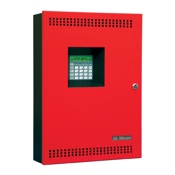
System Components Main Fire Control Panel Figure 1 FA-300 LCD All FA-300 LCD series panels have the following features: • LCD display • Two six-zone ICAC-306 Input Class A converter adder modules may be used for Class A (Style D) wiring of Initiating circuits. •... -
Page 14: Relay Module: 12 Relays
A.C. ON ALARM SUPV TRBL CPU FAIL SYSTEM RESET RAM-300LCDW SIGNAL ENTER SILENCE painted box FIRE MENU DRILL BUZZER CANCEL SILENCE LAMP INFO TEST Remote annunciator module, LCD display, red Advanced Life Safety Solutions RAM-300LCDR FA-300 SERIES painted box Remote Annunciator... -
Page 15: Smart Relay Module
System Components Smart Relay Module Model Description SRM-312W Smart relay module (12 relays) with white enclosure SRM-312R Smart relay module (12 relays) with red enclosure Advanced Life Safety Solutions FR-320 SERIES REMOTE RELAY Input Class A converter: Six Circuits Model Description Input Class A converter module (six circuits). -
Page 16: 4.10 Active End-Of-Line Resistor
System Components 4.10 Active end-of-line resistor The ELRX-300 are power-saving end-of-line resistors that eliminate the need for an additional battery cabinet or larger batteries in order to meet the 60 hour standby requirement. Model Description ELRX-300 Active end-of-line resistor without plate BLACK ELRX-300R Active end-of-line resistor with end-of-line red plate... -
Page 17: Mechanical Installation
Mechanical Installation Installing the Enclosure Install the FA-300 series fire alarm panel enclosure as shown below for the 12 zone, eight zone, and six zone models. Mount enclosure surface mount using the four mounting holes, as shown and the screws provided. -
Page 18: Figure 3 Enclosure Dimensions, Semi-Flush Mounting And Trim Ring
Mechanical Installation flush mount the enclosure into the wall. Peel the adhesive cover from the trim ring and stick to the wall surface around the enclosure, after the wall is finished. 11" 1.5" PLACE FA-UNIV-TRB TRIM RING OVER BACKBOX 17" 20.5"... -
Page 19: Bbx-1024Ds And Bbx-1024Dsr Mechanical Installation
Mechanical Installation BBX-1024DS and BBX-1024DSR Mechanical Installation The BBX-1024DS and BBX-1024DSR are suitable for flush or surface mounting, and have a built-in trim ring. Dimensions of enclosure (minus built-in trim ring) 14.5” x 4.2” x 26” Distance between horizontal mounting screws 12”... -
Page 20: Installing The Adder Modules
Mechanical Installation Installing the Adder Modules FA-300 series fire alarm panels come pre-assembled with all components and boards except for adder modules. Module installation locations are shown in Figures 6 and 7. Refer to "6.1.1 Connectors and Jumpers on the Main Fire Alarm Board" on page 24 for jumper or DIP switch settings and see "7.6 Wiring Tables and Information"... -
Page 21: Figure 7 Installation Of Adder Modules For Fa-300 Lcd
Mechanical Installation MAIN FIRE PANEL BOARD CLASS-A converter board for detection circuits ICAC-306 LCD configuration (6 circuits ) tool - CFG-300 plugged into the LCD DISPLAY socket shown. S Y S T E M N O R M A L CLASS-A converter 1 8 : 0 1 M O N 2 0 0 3 - 0 4 - 0 5 board for indicating... -
Page 22: Connections, Dip Switches, And Jumpers
Connections, DIP Switches, and Jumpers Main Fire Alarm Board For PC programming use UIMA interface module not UL-864 or ULC-S527 listed. Please refer to Document LT-929 for details Telephone line JW7- Normally Open Telephone line S Y S T E M N O R M A L RS-485 for 1 8 : 0 1 M O N 2 0 0 3 - 0 4 - 0 5 annunciators... -
Page 23: Figure 9 Main Fire Alarm Board Connections, Dip Switches And Jumpers For Fa-300 Lcd
Connections, DIP Switches, and Jumpers For PC programming use UIMA interface module not UL-864 or ULC-S527 listed. Please refer to Document LT-929 for details Telephone line Telephone line Normally open S Y S T E M N O R M A L RS-485 for 1 8 : 0 1 M O N 2 0 0 3 - 0 4 - 0 5 annunciators... -
Page 24: Icac-306 Input Class A Converter Adder Module
Connections, DIP Switches, and Jumpers 6.1.1 Connectors and Jumpers on the Main Fire Alarm Board Cable from P1 of the PR-300 polarity reversal and city tie module connects here. Otherwise not used. Cable from connector P1 of the RM-312 or RM-306 relay adder module connects here. -
Page 25: Ocac-304/302 Output Class A Converter Adder Module
Connections, DIP Switches, and Jumpers positive and negative terminals marked DET OUT and the circuit return wires are brought back to the converter module to positive and negative terminals marked DET RET. To convert all 12 initiating circuits of a FA-312 Fire Alarm Panel, two of these ICAC-306 input Class A converter adder modules are required. -
Page 26: Figure 12 Rm-312 Twelve Relay Adder Module
Connections, DIP Switches, and Jumpers jumpers located below the relays are used to select either normally open contacts or normally closed contacts. Connect to P6 on the main fire alarm board INDIVIDUAL GREEN RELAY STATUS LEDs RELAY 1 RELAY 2 RELAY 4 RELAY 5 RELAY 6... -
Page 27: Rm-306 Six Relay Adder Module
Connections, DIP Switches, and Jumpers RM-306 Six Relay Adder Module Cable from P1 of the RM-306 is connected to P6 on the Main Fire Alarm Board. The jumpers located above each relay on the RM-306 are used to configure the relays. The jumpers located below the relays are used to select either normally open contacts or normally closed contacts. - Page 28 Connections, DIP Switches, and Jumpers The following hardware configuration must be performed before installing the PR-300. 6.6.1 PR-300 jumper settings Cable connects to P3 on the Main Board P2 & JW4 Not used. Jumper JW4 remains on board. The Alarm Transmit signal to the PR-300 can be programmed to turn OFF when signal silence is active.
-
Page 29: Field Wiring
Field wiring Main Fire Alarm Board Field Wiring Wire devices to the terminals as shown in the figures that follow. Refer to the Wiring Tables for wire gauges and to Appendix C: Specifications for specifications. Caution: Do not exceed power supply ratings. 7.1.1 Initiating Circuit Wiring Wiring diagrams for the initiating circuits are shown below. -
Page 30: Figure 17 Initiating Circuit- Class A Or Style D Wiring
Initiating circuit– Class A or Style D wiring 7.1.2 Indicating Circuit Wiring The FA-300 Series Fire Alarm supports Class B or Style Y and Class A Style Z wiring for its Ω indicating circuits. Each circuit is supervised by a 3.9 k end-of-line resistor. -
Page 31: Figure 19 Indicating Circuit -Class A Or Style Z Wiring
Field wiring OCAC-304 CLASS A STYLE Z CONVERTER MODULE FIRE ALARM MAIN BOARD WIRING INDICATING CIRCUIT 1 INDICATING CIRCUIT #1 INDICATING CIRCUIT #2 STYLE Z WIRING 2 MORE INDICATING INDICATING CIRCUITS NOT SHOWN CIRCUIT 2 BELL STROBE HORN Figure 19 Indicating circuit –Class A or Style Z wiring 7.1.3 Four Wire Smoke Detector Wiring FIRE ALARM MAIN BOARD... -
Page 32: Relay Adder Module Wiring
Field wiring 7.1.4 Dialer Wiring If you have Fire Alarm Panel Models FA-301-12LDW, FA-301-12LDR, and FA-301-8LDW there is a dialer on board and terminals marked Line 1 and Line 2 must be wired as shown in Figure 21 below. FIRE ALARM MAIN BOARD RJ31X GREEN LINE-1... -
Page 33: Figure 23 Relay Per Zone (Rm-306) Terminal Connection
Field wiring RM-306 6 RELAY ADDER MODULE NORMALLY OPEN OR NORMALLY OPEN RELAY NORMALLY CLOSED CONNECTION CIRCUIT #1 NO/NC CONNECTION IS SELECTED BY JUMPER NORMALLY CLOSE ON RELAY BOARD. RELAY CONNECTION CIRCUIT #2 NO/NC ALL RELAY CONTACTS 28V DC, 1 AMP RESISTIVE LOAD RELAY NOTE: ALL RELAYS ARE POWER LIMITED... -
Page 34: Connecting To A 3G4010Cf Interface Device
Field wiring Connecting to a 3G4010CF Interface Device For information on Compatible Receivers see "12.0 Appendix A: Compatible Receivers" on page 81. A typical connection is shown in Figure 24. The 3G4010CF is powered separately from the PCS-100 and requires 2 DSC RM-2 relays (sold separately). The PCS-100 Passive Communications Interface Board (sold separately) is also required. -
Page 35: Polarity Reversal And City Tie Module (Pr-300) Wiring
Field wiring Polarity Reversal and City Tie Module (PR-300) Wiring Wire PR-300 Polarity Reversal and City Tie Module (if used) as shown in Figure 25, below. See "12.0 Appendix A: Compatible Receivers" on page 81 for module specifications. Power Limited cable type FPL, FPLR or FPLP must be used. For USA installation, the installer must use Atlantic Scientific (Tel: 407-725-8000), Model #24544 Protective Device, or similar UL-Listed QVRG secondary protector, as shown. -
Page 36: Power Supply Connection
Field wiring Power supply connection The power supply is part of the Main Chassis. The ratings are: Table 2 Power Supply Ratings Type Rating Electrical Input rating 120VAC, 60Hz, 3A\ 240 VAC, 50 Hz, 1.5A fuse Power supply total current 6A maximum Battery fuse on Main 10A, slow blow micro fuse... -
Page 37: Wiring Tables And Information
Field wiring Wiring Tables and Information Table 3 Initiating Circuit Wiring Wire gauge Maximum wiring run to last device Feet Meters 2990 4760 1450 7560 2300 12000 3600 19000 5800 30400 9200 Notes: For Class A the maximum wiring run to the last device is divided by two. Ω... -
Page 38: Supervised Auxiliary Power (Regulated)
Field wiring 7.6.1 Four-Wire Smoke Power (regulated) This terminal is labeled 4-WIRE SUPPLY on the circuit board. 4-wire smoke power is provided for 4-wire smoke detectors. This filtered supply is supervised therefore a short will disconnect the power through the relay until the “RESET” key is pressed. This supply is rated at 22.3VDC regulated/300mA max/1V voltage drop maximum. -
Page 39: Turning On The Panel
Turning on the Panel Before Connecting the Power 1. To prevent sparking, do not connect the batteries. Connect the batteries after powering the system from the main AC supply. 2. Check that all modules are installed in the proper location with the proper connections. 3. -
Page 40: Connecting The Power
Turning on the Panel Connecting the Power After completing the steps in "8.1 Before Connecting the Power" on page 39: 1. Plug in the AC power. The A.C. ON LED illuminates, the Common Trouble LED flashes, and the buzzer sounds. 2. -
Page 41: Troubleshooting
Turning on the Panel Troubleshooting Table 5 Troubleshooting Symptoms Possible Cause When a circuit trouble occurs, its designated trouble indicator will be illuminated, as well as the Common Trouble LED and trouble buzzer. To correct the fault, check for open Circuit wiring on that circuit, and check that the circuit is not disconnected or bypassed. -
Page 42: Indicators, Controls And Operations
Indicators, Controls and Operations Refer to Figure 28 below which shows the LCD Display, the Keypad and Control Button locations. S Y S T E M N O R M A L 1 8 : 0 1 M O N 2 0 0 3 - 0 4 - 0 5 A.C. -
Page 43: Common Controls
Indicators, Controls and Operations If the buzzer is turned on in response to a non-latching trouble or supervisory, it is turned off if the condition causing it goes away and there is no other reason for it to be on. 9.1.2 A.C. -
Page 44: Common Relays
Indicators, Controls and Operations 9.2.2 SIGNAL SILENCE Button Press the SIGNAL SILENCE button when the panel is in alarm to deactivate any silenceable indicating circuits. Non-silenceable circuits are unaffected. Signals resound if there is a subsequent alarm. Pressing SIGNAL SILENCE again resounds all silenceable signals. This button does not function when the signal silence inhibit timer is running (see "6 Signal Silence Inhibit timer"... -
Page 45: Circuit Types
Indicators, Controls and Operations 9.3.2 Common Supervisory Relay The Common Supervisory Relay (labeled SUPERVISORY RELAY on the circuit board) activates when the common supervisory sequence is activated as the result of an alarm or any un-bypassed latching or non-latching supervisory circuit. The relay is turned off if all non- latching supervisory circuits are restored and there are no latching supervisory circuits active. - Page 46 Indicators, Controls and Operations being used. If four seconds is too long a response time for pull stations, then wire them separately on a non-verified alarm circuit. An alarm condition causes the Common Alarm LED to illuminate red. 9.4.4 Sprinkler Alarm (for Sprinkler Flow Sensors) Sprinkler alarms are identical to normal non-verified alarms unless water flow retard operation is enabled.
- Page 47 Indicators, Controls and Operations 9.4.9 Trouble-Only The Trouble-Only circuit monitors a Trouble condition from an external device such as QX- 5000 Audio System. An activation of a Trouble-Only circuit causes the TRBL LED to flash at the Trouble rate. Both open and short circuits generate a non-latching Trouble condition. 9.4.10 Indicating (Signal) Circuit Types 9.4.11 Silenceable Signal The silenceable signal circuit is used for audible devices such as bells and piezo mini-horns...
-
Page 48: Evacuation Codes
Indicators, Controls and Operations Evacuation Codes Continuous On 100% of the time Temporal Code 3 of 0.5 second on, 0.5 second off, then 1.5 second pause March Code 0.5 second on, 0.5 second off California Code 5 seconds on, 10 seconds off CONTINUOUS CONTINOUS 0.5s... - Page 49 Indicators, Controls and Operations • If signals have been silenced as a result of the SIGNAL SILENCE button or the Auto Signal Silence Timer, the signals resound and the Auto Signal Silence Timer, if configured, is restarted • Any additional non-disconnected strobes associated with the new input are activated continuously •...
-
Page 50: Supported Protocols And Devices
10.0 Supported Protocols and Devices 10.1 Synchronous Strobes The synchronous strobe models that are supported by the FA-300 panel include Mircom models FHS-240 and FS-240. A separate compatibility list is available for different supported models. Strobes can be configured as normal (not synchronized). See . Any selection made is system- wide (that is, the selection applies to all the circuits in the system that are configured as strobes). -
Page 51: Table 6 I3 Detector Leds
Supported Protocols and Devices Z o n e - 1 O p e n T r b . 1 / 1 10.3.2 Communication Trouble If there is a fault in the line or the line is too noisy, the panel cannot communicate with the devices. -
Page 52: Configuration
11.0 Configuration There are three methods of configuring the FA-300 LCD Series Fire Alarm Panels: • Direct configuration using the main LCD display and the menu buttons. • Using a PC or laptop computer with a UIMA adapter. • Using a PC or laptop computer with remote connection (must use fire alarm with built-in UDACT). -
Page 53: 11.1 Accessing Configuration Mode
Configuration 11.1 Accessing Configuration Mode To access configuration mode 1. Press the Menu button on the front panel display. 2. Enter your passcode. The minimum number of digits for the passcode is four and the maximum is ten. The passcode must be numerical values only. The default passcode is 1111. 3. - Page 54 Configuration -Command Menu- 1. FA-300 Config 2. Config Info 3. Set Time 4. Set Password 5. View EventLog 6. Clear EventLog 7. Walk Test 8. I3 Loop test 9. Dialer Config 10.Test Dialer 11.Bypass Det Ckt 12.Bypass NAC Ckt 13.Aux Disc 14.Exit Figure 33 Command Menu...
-
Page 55: Panel Config (Command Menu)
Configuration 11.3 Panel Config (Command Menu) The FA-300 configuration menu is shown in Figure 34. -FA-300 Config- 1. Features 2. Inp Zone 3. I3 Zone 4. Opt. Zone 5. Correlation 6. Inp Zone Label 7. Opt Zone Label 8. Default Config Figure 34 FA-300 Config menu 11.4 Feature Config... -
Page 56: Table 7 Feature Config Menu
Configuration Table 7 describes the options in the Feature Config menu. Table 7 Feature Config menu Name in the FA-300 Feature Default Description Configuration Utility 1 Manual Signal Silence Use this function to enable or disable the SIGNAL SILENCE [X] ENABLE->Default M a n u a l S i g . - Page 57 Configuration Table 7 Feature Config menu Name in the FA-300 Feature Default Description Configuration Utility If enabled, the Common Alarm Command Menu - FA-300 Config - Features Relay and the Common 7 “Aux. disconnect” disconnects Supervisory Relay, in addition Common Alarm Relay and to the Auxiliary Alarm Relay, Common Supervisory Relay are disconnected when you...
- Page 58 14 Strobe Type [X] NORMAL ->Default used in the system. The selection is system-wide and [ ] MIRCOM S t r o b e T y p e applies to all indicating circuits [ ] FARADY Strobe configured as strobes.
-
Page 59: Figure 33 Command Menu
Configuration Command Menu - FA-300 Config 11.4.1 Inp Zone I n i t i a t i n g Z o n e 1 Z o n e - 1 2 Z o n e - 2 1 2 Z o n e 1 2 Command Menu - FA-300 Config - Ipt. - Page 60 Configuration Command Menu - FA-300 Config 11.4.3 Opt Zone I n d i c a t i n g Z o n e 1 N A C - 1 2 N A C - 2 3 N A C - 3 4 N A C - 4 Command Menu - FA-300 Config - Opt.
- Page 61 Configuration Use the keypad described below for entering a message. Command Menu - FA-300 Config - Ipt. Zone Label [Zone-1 ]->Default 1.Initiating zone label [Zone-12 ]->Default Zone-1 Label KEYPAD TRANSLATION AS MARKED ON THE KEYS SEQ refers to the number of times the key must be pressed Zone-1 to display the number or letter.
-
Page 62: Config. Info. (Command Menu)
Configuration Command Menu --> FA-300 Config 11.4.7 Default Configuration L o a d t h e d e f a u l t s e t t i n g s ? Y Use this menu to load the default configuration in the panel. Press the up and down arrow buttons to select between Y/N. -
Page 63: Set Time (Command Menu)
Configuration 11.6 Set Time (Command Menu) 1 Daylight Save 2 Time Clock 3 Compensation Command Menu - Set Time 11.6.1 Daylight Saving Use this menu to enable [X] DISABLE ->Default daylight savings time. [ ] ENABLE Daylight Saving [X] DISABLE Use this menu to set the Command Menu - Time Clock time and date. -
Page 64: Set Password (Command Menu)
Configuration 11.7 Set Password (Command Menu) Enter new passcode Re-enter passcode Use this menu to change the passcode. The minimum If the passcode does not match, the following number of digits is 4 and the message appears. 1111 -> Default maximum number is 10. -
Page 65: Clear Eventlog (Command Menu)
Configuration 11.9 Clear EventLog (Command Menu) -Select Log- 1 Alarm Log 2 General Log 3 All Logs Select the type of log to clear. Press the ENTER button. The system confirms before clearing logs. Use this menu to clear alarm logs, general logs, or both. C l e a r a l l t h e s e l e c t e d l o g ( s ) ? Y Press the ENTER button to confirm or the... -
Page 66: I3 Loop Test (Command Menu)
Configuration indication circuits sound for one burst. If the second selected circuit is activated, the indication circuits sound for two bursts, and so on. This means that if, for example, circuits 1, 3 and 5 are selected for the walk test, the indicating circuits sound with one, two and three bursts respectively. -
Page 67: Dialer Config (Command Menu)
Configuration If the i maintenance test is selected within six minutes after power-up or reset, the following information message is displayed. T h e s e l e c t e d z o n e i s n o t r e a d y y e t Figure 42 test not ready If a zone is selected that is not configured as an i... -
Page 68: Figure 45 Account Info Menu
Configuration Command Menu-->Dialer Config 11.12.1Account Info - A c c o u n t I n f o - 1 A c c o u n t # 1 I D 2 A c c o u n t # 1 T e l 3 A c c n t # 1 F o r m a t 4 A c c o u n t # 2 I D 5 A c c o u n t # 2 T e l... -
Page 69: Figure 46 Telephone Line Menu
Configuration Command Menu - Dialer Config - Account Info 4. Account #2 Identification Same as Account #1. 654321->Default A c c o u n t # 2 I D : Command Menu - Dialer Config - Account Info 5.Account #2 Telephone Number Same as Account #1. -
Page 70: Figure 47 Report Options Menu
Configuration Command Menu - Dialer-Config - Telephone Line Use this function to let the 3. Line #1 Wait for Dial Tone system know whether or not to wait for a dial tone before dialing. [X] ENABLE ->Default Cell phone setup for the dialer L i n e # 1 W a i t D i a l t o n e [ ] DISABLE requires that the system not wait... -
Page 71: Figure 48 Time Parameter
Configuration Command Menu - Dialer-Config - Report Options Use this menu to set the 3. Supervisory priority account priority for reporting supervisory [X] Account 1->Def troubles. If the priority is S U P V P r i o r i t y [ ] Account 2 set for account #1, then the dialer will try account #1... - Page 72 Configuration Use this menu to set the test Command Menu - Dialer-Config - Time Parameter report date for the cell phone 2.Cellular report date setup. If the date is set to 0, there will be no test reporting for cell phone or regular telephone line.
-
Page 73: Test Dialer (Command Menu)
Configuration 11.13 Test Dialer (Command Menu) -Dialer Test- 1. L#1 Manual test 2. L#2 Manual test 3. Reset Dialer Figure 49 Dialer Test menu Press ENTER to test line #1. Press CANCEL to 1.L#1 Manual test exit this menu. For a description of test messages, see "11.13.1 Dialer Test Messages"... -
Page 74: Bypass Det Ckt (Command Menu)
Configuration Waiting for availability of the receiver. The Waiting for Acktone receiver confirms the availability by sending an ack tone. This message indicates that either the telephone Failed No Acktone number may be wrong or the receiver is not available. When sending events to the receiver, the display Reporting Event Now will toggle between this message and “Waiting for... -
Page 75: Bypass Nac Ckt (Command Menu)
Configuration 11.15 Bypass NAC Ckt (Command Menu) Indicating zones can be bypassed Bypass Det Zone individually. This bypass command will allow you to scroll through all indicating 1.Zone-1 zones. Press ENTER to bypass the zone or [ ]Bypassed scroll up or down to un-bypassed (normal connected circuit). -
Page 76: Figure 50 Detection Circuit Message
Configuration 11.18.1Example 1 (detection circuit) Event 02 of 09, OPEN TRB on initiating circuit Z-01 in the EAST LOBBY ENTRANCE with process type as VERIFIED ALARM and the event occurred on 2003/02/02 at 18:01 TUESDAY. Z O N E P ro c ess P h ysic al M essag e T yp e... -
Page 77: Figure 52 Ac Power Fail Message
Configuration 11.19 AC Power Fail The AC power fail trouble is generated when the power drops below the UL specified value. The trouble is restored when the power returns to the normal value. T ro u b le c o d e T ro u b le In fo T ro u b le T yp e A C P o w e r F a i l... -
Page 78: Figure 54 Ground Fault Message
Configuration 11.21 Ground Fault T ro u b le co d e T ro u b le Info T ro u b le T yp e G r o u n d F a u l t T r b : 0 x 0 3 I n f o : 0 x 0 0 0 1 "IN F O "... -
Page 79: Figure 56 Four-Wire Smoke Detector Supply Message
Configuration RESET button to restore power to the system. If the short is removed, the panel returns to normal; otherwise the trouble message remains. T ro u b le co d e T ro u b le Info T ro u b le T yp e 4 W i r e P w r . -
Page 80: Figure 58 Module Missing Message
Configuration If any of the modules are not plugged in, the following trouble message appears: T ro u b le co d e T ro u b le In fo T ro u b le T yp e C t y T i e / R M x x x m i s s i n g T r b : 0 x 0 3 I n f o : 0 x 0 0 0 1 "IN F O "... -
Page 81: Appendix A: Compatible Receivers
12.0 Appendix A: Compatible Receivers The dialers that are built into select models of the FA-300 Series Fire Alarm Control Panels are compatible with the following Digital Alarm Communicator Receivers (DACR): Table 9 Compatible Receivers DACR Receiver Model Protocols SurGard MLR2 Multi-Line Receiver (ULC, ULI... -
Page 82: Appendix B: Reporting
13.0 Appendix B: Reporting 13.1 Ademco Contact-ID 13.1.1 FA-300 Event Codes Table 10 Ademco Event Code Event Description Event Family Qualifier Code Group # Contact # Phone Line #1 trouble detected Trouble New event 1 351 Phone Line #2 trouble detected Trouble New event 1 352... -
Page 83: 13.2 Security Industries Association Sia-Dcs
Appendix B: Reporting 13.2 Security Industries Association SIA-DCS SIA protocol does not define indicating zone troubles, but lists it as Untyped Zone Trouble/ Restore. 13.2.1 FA-300 Event Codes Table 11 SIA Event Codes Event Description Event Family Qualifier Event Parameter Code Phone Line #1 trouble detected Trouble... -
Page 84: Appendix C: Specifications
14.0 Appendix C: Specifications Table 12 FA-300 LCD Series Specifications FA-300 LCD Fire Control Panel Chassis General Digital Signal Processor (DSP) based design. Fully configurable using front panel LCD display with Password Access. Indicating (NAC) 4 supervised Style Z (Class B) indicating circuits, configured as strobes or Circuits audibles. -
Page 85: Table 13 Fa-300 Lcd System Modules And Annunciators
10 Ah Protection 10 A on board (F1) slow blow micro fuse Compliance System Model FA-300 Series LED Version Fire Alarm Control Panel System Type Local, Auxiliary (using PR-300), Remote Protected Premises Station (using PR-300 or FA-301-12LDR, FA-301-12LDW, or FA-301-8LDW) Central Station Protected Premises (using FA-301-12LDR, FA-301- 12LDW, or FA-301-8LDW). - Page 86 Appendix C: Specifications Table 13 FA-300 LCD System Modules and Annunciators (Continued) FA-300 LCD Series Modules and Annunciators PR-300 Polarity Reversal and City Tie Module City Tie power limited / 24 VDC unfiltered / 250 mA Ω max / 14 trip coil Polarity Reversal power limited / 24 VDC open / 12 VDC at...
-
Page 87: Appendix D: Power Supply And Battery Calculations
15.0 Appendix D: Power Supply and Battery Calculations Use the form below to determine the required secondary power supply (batteries). IMPORTANT NOTICE The main AC branch circuit connection for Fire Alarm Control Panel must provide a dedicated continuous power without provision of any disconnect devices. Use #12 AWG wire with 600-volt insulation and proper over-current circuit protection that complies with the local codes. - Page 88 ([STANDBY (A) ______ ] X [(24 or 60 Hours) ___ ]) + ([ALARM (B) ______ ] X [Alarm in Hr.] _____) = (C) ______AH Total Alarm Current: Must be 6 amperes or less for FA-300 Series. Indicating Circuits must not to exceed 5 amperes.
-
Page 89: Warranty And Warning Information
As the only individual in contact with system users, please bring each item in this warning to the attention of the users of this Mircom System. Failure to properly inform system end-users of the circumstances in which the system might fail may result in over-reliance upon the system. - Page 90 11. Battery Failure. If the Mircom System or any device connected to the system operates from batteries it is possible for the batteries to fail. Even if the batteries have not failed, they must be fully charged, in good condition, and installed correctly.
- Page 91 20. Integrated Products. Mircom System might not function as intended if it is connected to a non-Mircom product or to a Mircom product that is deemed non-compatible with a particular Mircom System.
- Page 92 U.S.A CANADA - Main Office © Mircom 2017 25 Interchange Way 4575 Witmer Industrial Estates Printed in Canada Subject to change without prior notice Niagara Falls, NY 14305 Vaughan, ON L4K 5W3 Tel: (888) 660-4655 Tel: (888) 660-4655 www.mircomgroup.com (905) 660-4655...
Need help?
Do you have a question about the FA-300 Series and is the answer not in the manual?
Questions and answers