Sign In
Upload
Manuals
Brands
Mindray Manuals
Medical Equipment
DC-70
User Manuals: Mindray DC-70 Gynecology Ultrasound
Manuals and User Guides for Mindray DC-70 Gynecology Ultrasound. We have
3
Mindray DC-70 Gynecology Ultrasound manuals available for free PDF download: Service Manual
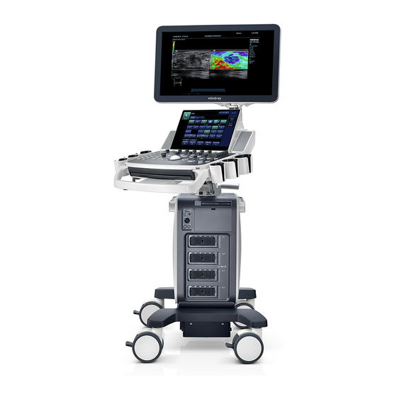
Mindray DC-70 Service Manual (295 pages)
Diagnostic Ultrasound System
Brand:
Mindray
| Category:
Medical Equipment
| Size: 12.42 MB
Table of Contents
Table of Contents
3
Revision History
9
Intellectual Property Statement
10
Applicable for
10
Statement
10
Customer Service Department
11
Safety Precautions
13
Meaning of Signal Words
13
Symbols
13
Meaning of Safety Symbols
13
Warning Labels
14
General Symbols
14
Safety Precautions
16
Electric Safety
16
Mechanical Safety
17
Personnel Safety
17
Other
17
Specifications
19
Overview
19
Intended Use
19
Introduction of each Unit
19
Peripherals Supported
28
Specifications
28
Dimensions & Weight
28
Electrical Specifications
28
Environmental Conditions
28
Monitor Specification
29
System Installation
31
Preparations for Installation
31
Electrical Requirements
31
Installation Conditions
32
Confirmation before Installation
33
Unpacking
33
Unpacking Process
33
Check
35
Installation of Main Unit
35
Open up the Monitor
36
Connecting the Power Cord
36
Connecting ECG
37
Installing Probe/Gel Holder
37
Connecting the Transducer
38
Installing Peripherals
39
Connecting the Footswitch
39
Installing a Graph / Laser Printer
40
Installing Video Printer
42
Position a Printer
42
Installing Barcode Scanner
43
System Configuration
44
Running the System
44
Enter Doppler
44
System Preset
46
Print Preset
47
Network Settings
47
Network Configuration
49
Security
50
DICOM/HL7 Preset
51
Check System Information
53
Product Principle
55
Hardware System Diagram
55
Ultrasound Front-End Unit
56
Probe Board
57
TR Board
58
CW Module
59
Engine Board
59
Module
61
ECG Module
62
Ultrasound Back-End Unit
62
PC Module
63
PC Carrier Board
63
GPU Module
64
Storage Device
64
Wireless Network Module
64
IO Interface Module
64
Extension and Distribution
65
Video Extension Function
65
Audio Interface
66
SATA Interface
66
USB Distribution
66
Network Interface
67
PCIE Interface Distribution
68
Other IO Extension
68
Power Supply Unit
69
AC Connecting Board
70
AC-DC Module
70
To 12V Power Conversion Board
70
DC-DC Board
71
PHV Board
71
Time Sequence of Power-On
71
User Interaction Unit
72
Control Panel Assembly
72
Primary Display Assembly
73
Secondary Display Assembly
73
Function and Performance Checking Method
75
Note
75
System Running Status
75
Running Status
75
Working Condition
75
General Exam
76
Check Flow
76
Checking Content
76
Function Checking
79
Checking Flow
79
Performance Test
85
Test Process
85
Test Content
85
Software Installation &Maintenance
93
Enter Maintenance
93
Set Installment
93
Software Installation/Restoration
96
Enter Windows
96
Software Maintenance
96
Export Log
96
Fast Startup
97
Data Backup and Storage
100
Preset Data Management
100
Patient Data Backup and Restoration
101
Introduction on Hard Disk's Partitions
102
Adjustments
103
Monitor Adjustment
103
Position Adjustment
103
Brightness and Contrast Adjustment
104
Monitor Test
105
Touch Screen Test
106
Control Panel Adjustment
107
Caster Adjustment
108
Field Replaceable Unit
109
Exploded View
110
Assembly Exploded View
111
Monitor Assembly (A0)
111
Monitor Support Arm Assembly (B0)
113
Main Control Panel Assembly (C0)
115
Control Panel Support Arm Assembly (D0)
121
Main Unit Assembly (E0)
123
Base Assembly (F0)
132
Base Power Box Assembly (G0)
133
Cable (H0)
134
Fusion Imaging Assembly (I0)
136
Structure and Assembly/Disassembly
139
Structure of the Entire System
139
Preparation
140
Disassembly Tools Required
140
Engineers Required
140
Disassembly Requirements
140
Assembly/Disassembly
140
Display (Monitor) Assembly
142
Probe Board Assembly
143
Disassembling ECG Assembly
144
Outlet Fan
145
Disassembling Battery Assembly
146
IO Board/Wifi Board
147
Hdd
149
Electronic Assembly on the Base
151
DC Box Assembly
153
PC Assembly
155
Engine Board and TR Board
157
DVD
158
Inlet Fan
159
Motherboard
160
Control Panel Assembly
162
Face Cover Assembly of the Speaker/Speaker
167
Caster
169
Module Package
169
The Material Package of CW Assembly
171
Support Arm Assembly of the Control Panel
172
Support Arm Assembly of the Display
176
Keyboard Assembly
179
To 12V Power Conversion Board
180
AC-DC Module
180
AC Connecting Board
181
Power Input Assembly
182
Magnetic Generator Trolley
183
Magnetic Navigator
185
Optional Installation/Assembly
191
Installing Optional Software
191
System Diagnosis and Support
201
General Status Indicator
201
Indicators on Control Panel
201
Display Status Indicator
202
Status of Entire Device
203
Status Indicator of Gel Warmer
203
Get Entire Device Started
204
Power-On of Entire Device Supplied by AC
205
Start-Up Process of BIOS
205
Windows Start-Up
205
Start-Up of Doppler
206
Alarming and Errors
208
Battery Error
208
Abnormal Voltage of System Power
208
Fan Error
210
Gel Warmer Abnormality
212
Other Errors
213
Self Test
213
Self Test Introduction
213
Operation Procedure of Maintenance Self Test
213
User Self Test
218
Test Report
220
Care and Maintenance
223
Overview
223
Tools, Measurement Devices and Consumables
223
Routine Maintenance Items
223
Cleaning
225
System Cleaning
225
Peripherals Cleaning
229
Check
229
General Check
229
System Performance Check
230
Check for Peripherals and Optional Functions
231
Mechanical Safety Inspection
231
Electrical Safety Inspection
233
Troubleshooting of Regular Malfunctions
235
System Cannot Power on
235
Related Modules or Boards
235
Key Points Supporting Troubleshooting
235
Troubleshooting as the System Unable to Power on
236
System Cannot Start
237
Related Modules or Boards
237
Key Points Supporting Troubleshooting
237
The System Cannot Perform Troubleshooting
237
Image Problems
238
Related Modules or Boards
238
Key Points Supporting Troubleshooting
238
Image Troubleshooting
239
Probe Socket System Malfunction
239
Related Modules or Boards
239
Key Points Supporting Troubleshooting
239
Troubleshooting of Probe Socket System
240
IO Interface System Failure
240
Related Modules or Boards
240
Key Points Supporting Troubleshooting
240
Troubleshooting of IO Interface System
241
Control Panel Failure
241
Related Modules or Boards
241
Key Points Supporting Troubleshooting
242
Troubleshooting of Control Panel
242
LCD Display Failure
243
Related Modules or Boards
243
Key Points Supporting Troubleshooting
243
Troubleshooting of the Monitor
243
ECG Module Failure
244
Related Modules or Boards
244
Key Points Supporting Troubleshooting
244
Troubleshooting for ECG Module
244
Appendix A Electrical Safety Inspection
247
Appendix B Phantom Usage Illustration
265
Appendix C Description of Self Test Items
269
Advertisement
Mindray DC-70 Service Manual (281 pages)
Diagnostic Ultrasound System
Brand:
Mindray
| Category:
Medical Equipment
| Size: 13.64 MB
Table of Contents
Table of Contents
3
Revision History
9
Intellectual Property Statement
10
Applicable for
10
Statement
10
Responsibility on the Manufacturer Party
11
Customer Service Department
11
1 Safety Precautions
13
Meaning of Signal Words
13
Symbols
13
Meaning of Safety Symbols
13
Warning Labels
14
General Symbols
14
Safety Precautions
16
Electric Safety
16
Mechanical Safety
17
Personnel Safety
17
Other
17
2 Specifications
19
Overview
19
Intended Use
19
Introduction of each Unit
19
Peripherals Supported
28
Specifications
28
Dimensions & Weight
28
Electrical Specifications
28
Environmental Conditions
28
Monitor Specification
29
3 System Installation
31
Preparations for Installation
31
Electrical Requirements
31
Installation Conditions
32
Confirmation before Installation
33
Unpacking
33
Unpacking Process
33
Check
35
Installation of Main Unit
35
Open up the Monitor
36
Connecting the Power Cord
36
Connecting ECG
37
Installing Probe/Gel Holder
37
Connecting the Transducer
38
Installing Peripherals
39
Connecting the Footswitch
39
Installing a Graph / Laser Printer
40
Installing Video Printer
42
Position a Printer
42
Installing Barcode Scanner
43
System Configuration
44
Running the System
44
Enter Doppler
44
System Preset
46
Print Preset
47
Network Settings
47
Network Configuration
49
Security
50
DICOM/HL7 Preset
51
Check System Information
53
4 Product Principle
55
Hardware System Diagram
55
Ultrasound Front-End Unit
56
Probe Board
57
TR Board
58
CW Module
58
Engine Board
59
Module
60
ECG Module
61
Ultrasound Back-End Unit
61
PC Module
62
GPU Module
62
Storage Device
62
Wireless Network Module
62
PC Carrier Board
62
IO Interface Module
63
Extension and Distribution
64
Video Extension Function
64
Audio Interface
65
SATA Interface
65
USB Distribution
65
Network Interface
66
PCIE Interface Distribution
67
Other IO Extension
67
Power Supply Unit
68
AC-DC Module
69
Adapter Board of the Control Panel
69
DC-DC Module
69
PHV Module
69
Time Sequence of Power-On
69
User Interaction Unit
70
Control Panel Assembly
70
Primary Display Assembly
70
Secondary Display Assembly
71
5 Function and Performance Checking Method
73
Note
73
System Running Status
73
Running Status
73
Working Condition
73
General Exam
74
Check Flow
74
Checking Content
74
Function Checking
77
Checking Flow
77
Performance Test
83
Test Process
83
Test Content
83
6 Software Installation &Maintenance
91
Enter Maintenance
91
Set Installment
91
Software Installation/Restoration
94
Enter Windows
94
Software Maintenance
94
Export Log
94
Fast Startup
95
Data Backup and Storage
98
Preset Data Management
98
Patient Data Backup and Restoration
99
Introduction on Hard Disk's Partitions
100
7 Adjustments
101
Monitor Adjustment
101
Position Adjustment
101
Brightness and Contrast Adjustment
102
Monitor Test
103
Touch Screen Test
104
Control Panel Adjustment
105
Caster Adjustment
106
8 Field Replaceable Unit
107
Explosive View
108
Assembly Explosive View
109
Monitor Assembly (A0)
109
Monitor Support Arm Assembly (B0)
111
Main Control Panel Assembly (C0)
113
Control Panel Support Arm Assembly (D0)
120
Main Unit Assembly (E0)
121
Base Assembly (F0)
130
Base Power Box Assembly (G0)
131
Cable (H0)
132
9 Structure and Assembly/Disassembly
135
Structure of the Entire System
135
Preparation
136
Disassembly Tools Required
136
Engineers Required
136
Disassembly Requirements
136
Assembly/Disassembly
136
Display (Monitor) Assembly
138
Probe Board Assembly
139
Disassembling ECG Assembly
140
Outlet Fan
141
Disassembling Battery Assembly
142
IO Board/Wifi Board
145
Hdd
147
Electronic Assembly on the Base
149
DC Box Assembly
150
PC Assembly
151
Engine Board and TR Board
154
DVD
154
Inlet Fan
156
Motherboard
157
Control Panel Assembly
159
Face Cover Assembly of the Speaker/Speaker
164
Caster
166
Module Package
166
The Material Package of CW Assembly
168
Support Arm Assembly of the Control Panel
169
Support Arm Assembly of the Display
173
Keyboard Assembly
176
Power Input Assembly
177
Control Switch Board
178
AC Connecting Board (220 V)
178
FAN (AC-DC Fan)
179
10 Optional Installation/Assembly
181
Installing Optional Software
181
11 System Diagnosis and Support
191
General Status Indicator
191
Indicators on Control Panel
191
Display Status Indicator
192
Status of Entire Device
193
Status Indicator of Gel Warmer
193
Get Entire Device Started
194
Power-On of Entire Device Supplied by AC
195
Start-Up Process of BIOS
195
Windows Start-Up
195
Start-Up of Doppler
196
Alarming and Errors
198
Battery Error
198
Abnormal Voltage of System Power
198
Abnormal Temperature
199
Fan Error
200
PHV Error
201
Gel Warmer Abnormality
202
Other Errors
203
Self Test
203
Self Test Introduction
203
Operation Procedure of Maintenance Self Test
203
User Self Test
208
Test Report
210
12 Care and Maintenance
213
Overview
213
Tools, Measurement Devices and Consumables
213
Routine Maintenance Items
213
Cleaning
215
System Cleaning
215
Peripherals Cleaning
219
Check
219
General Check
219
System Performance Check
220
Check for Peripherals and Optional Functions
221
Mechanical Safety Inspection
222
Electrical Safety Inspection
224
13 Troubleshooting of Regular Malfunctions
225
System Cannot Power on
225
Related Modules or Boards
225
Key Points Supporting Troubleshooting
225
Troubleshooting as the System Unable to Power on
226
System Cannot Start
227
Related Modules or Boards
227
Key Points Supporting Troubleshooting
227
The System Cannot Perform Troubleshooting
227
Image Problems
228
Related Modules or Boards
228
Key Points Supporting Troubleshooting
228
Image Troubleshooting
229
Probe Socket System Malfunction
230
Related Modules or Boards
230
Key Points Supporting Troubleshooting
230
Troubleshooting of Probe Socket System
230
IO Interface System Failure
231
Related Modules or Boards
231
Key Points Supporting Troubleshooting
231
Troubleshooting of IO Interface System
232
Control Panel Failure
233
Related Modules or Boards
233
Key Points Supporting Troubleshooting
233
Troubleshooting of Control Panel
233
LCD Display Failure
234
Related Modules or Boards
234
Key Points Supporting Troubleshooting
234
Troubleshooting of the Monitor
235
ECG Module Failure
236
Related Modules or Boards
236
Key Points Supporting Troubleshooting
236
Mindray DC-70 Service Manual (273 pages)
Diagnostic Ultrasound System
Brand:
Mindray
| Category:
Medical Equipment
| Size: 12.71 MB
Table of Contents
Table of Contents
3
Revision History
9
Intellectual Property Statement
10
Applicable for
10
Statement
10
Customer Service Department
11
1 Safety Precautions
13
Meaning of Signal Words
13
Symbols
13
Meaning of Safety Symbols
13
Warning Labels
14
General Symbols
14
Safety Precautions
16
Electric Safety
16
Mechanical Safety
17
Personnel Safety
17
Other
17
2 Specifications
19
Overview
19
Intended Use
19
Introduction of each Unit
19
Peripherals Supported
28
Specifications
28
Dimensions & Weight
28
Electrical Specifications
28
Environmental Conditions
28
Monitor Specification
29
3 System Installation
31
Preparations for Installation
31
Electrical Requirements
31
Installation Conditions
32
Confirmation before Installation
33
Unpacking
33
Unpacking Process
33
Check
35
Installation of Main Unit
35
Open up the Monitor
36
Connecting the Power Cord
36
Connecting ECG
37
Installing Probe/Gel Holder
37
Connecting the Transducer
38
Installing Peripherals
39
Connecting the Footswitch
39
Installing a Graph / Laser Printer
39
Installing Video Printer
42
Installing a Wireless Printer
42
Position a Printer
43
Installing Barcode Scanner
44
System Configuration
45
Running the System
45
Enter Doppler
45
System Preset
46
Print Preset
47
Network Preset
47
DICOM/HL7 Preset
48
Check System Information
51
4 Product Principle
53
Hardware System Diagram
53
Ultrasound Front-End Unit
54
Probe Board
55
TR Board
55
CW Module
56
Engine Board
57
Module
58
ECG Module
59
Ultrasound Back-End Unit
59
PC Module
60
Storage Device
60
Wireless Network Module
60
PC Carrier Board
60
IO Interface Module
61
Extension and Distribution
62
Video Extension Function
62
Audio Interface
63
SATA Interface
63
USB Distribution
63
Network Interface
64
PCIE Interface Distribution
65
Other IO Extension
65
Power Supply Unit
66
AC-DC Module
67
DC-DC Module
68
PHV Module
68
Time Sequence of Power-On
68
User Interaction Unit
68
Control Panel Assembly
68
Primary Display Assembly
69
Secondary Display Assembly
69
5 Function and Performance Checking Method
71
Note
71
System Running Status
71
Running Status
71
Working Condition
71
General Exam
72
Check Flow
72
Checking Content
72
Function Checking
75
Checking Flow
75
Performance Test
81
Test Process
81
Test Content
81
6 Software Installation &Maintenance
89
Enter Maintenance
89
Set Installment
90
Software Installation/Restoration
92
Enter Windows
92
Software Maintenance
93
Export Log
93
Data Backup and Storage
93
Preset Data Management
93
Patient Data Backup and Restoration
94
Introduction on Hard Disk's Partitions
96
7 Adjustments
97
Monitor Adjustment
97
Position Adjustment
97
Brightness and Contrast Adjustment
99
Monitor Test
100
Monitor Parameter Setting
103
Touch Screen Adjustment
103
Touch Screen Brightness and Contrast Adjustment
103
Touch Screen Test
104
Control Panel Adjustment
104
Caster Adjustment
106
8 Field Replaceable Unit
107
9 Structure and Assembly/Disassembly
125
Structure of the Entire System
125
Preparation
126
Disassembly Tools Required
126
Engineers Required
126
Disassembly Requirements
126
Assembly/Disassembly
127
Display (Monitor) Assembly
128
Probe Board Assembly
129
Disassembling ECG Assembly
131
Outlet Fan
132
Disassembling Battery Assembly
133
IO Board/Wifi Board
136
Hdd
138
Electronic Assembly on the Base
140
DC Box Assembly
141
PC Assembly
142
Engine Board and TR Board
144
DVD
145
Inlet Fan
146
Motherboard
147
Control Panel Assembly
149
Face Cover Assembly of the Speaker/Speaker
154
Caster
156
Module Package
156
The Material Package of CW Assembly
158
Support Arm Assembly of the Control Panel
159
Support Arm Assembly of the Display
164
Keyboard Assembly
169
Power Input Assembly
169
Control Switch Board
171
AC Connecting Board (220 V)
171
FAN (AC-DC Fan)
172
10 Optional Installation/Assembly
173
Installing Optional Software
173
11 System Diagnosis and Support
185
General Status Indicator
185
Indicators on Control Panel
185
Display Status Indicator
186
The Status Indicator of the Batteries on IO Rear Board
186
Status of Entire Device
187
Status Indicator of Gel Warmer
187
Get Entire Device Started
188
Power-On of Entire Device Supplied by AC
189
Start-Up Process of BIOS
189
Windows Start-Up
189
Start-Up of Doppler
190
Alarming and Errors
192
Battery Error
192
Abnormal Voltage of System Power
192
Abnormal Temperature
193
Fan Error
194
PHV Error
195
Gel Warmer Abnormality
196
Other Errors
197
Self Test
197
Self Test Introduction
197
Operation Procedure of Maintenance Self Test
197
User Self Test
202
Test Report
204
12 Care and Maintenance
207
Overview
207
Tools, Measurement Devices and Consumables
207
Routine Maintenance Items
207
Cleaning
209
System Cleaning
209
Peripherals Cleaning
213
Check
213
General Check
213
System Performance Check
214
Check for Peripherals and Optional Functions
214
Mechanical Safety Inspection
216
Electrical Safety Inspection
218
13 Troubleshooting of Regular Malfunctions
219
System Cannot Power on
219
Related Modules or Boards
219
Key Points Supporting Troubleshooting
219
Troubleshooting as the System Unable to Power on
220
System Cannot Start
221
Related Modules or Boards
221
Key Points Supporting Troubleshooting
221
The System Cannot Perform Troubleshooting
221
Image Problems
222
Related Modules or Boards
222
Key Points Supporting Troubleshooting
222
Image Troubleshooting
223
Probe Socket System Malfunction
224
Related Modules or Boards
224
Key Points Supporting Troubleshooting
224
Troubleshooting of Probe Socket System
224
IO Interface System Failure
224
Key Points Supporting Troubleshooting
225
Troubleshooting of IO Interface System
226
Control Panel Failure
227
Related Modules or Boards
227
Key Points Supporting Troubleshooting
227
Troubleshooting of Control Panel
227
LCD Display Failure
228
Related Modules or Boards
228
Key Points Supporting Troubleshooting
228
Troubleshooting of the Monitor
229
ECG Module Failure
229
Related Modules or Boards
229
Key Points Supporting Troubleshooting
230
Troubleshooting for ECG Module
230
Appendix A Electrical Safety Inspection
231
Appendix B Phantom Usage Illustration
249
Appendix C Description of Self Test Items
251
Advertisement
Advertisement
Related Products
Mindray DC-70T
Mindray DC-70 Pro
Mindray DC-70 Exp
Mindray DC-70S
Mindray DC-70W
Mindray DC-70 CV
Mindray DC-70 Plus
Mindray DC-75
Mindray DC-78
Mindray DC-75 Exp
Mindray Categories
Medical Equipment
Diagnostic Equipment
Measuring Instruments
Monitor
Water Pump
More Mindray Manuals
Login
Sign In
OR
Sign in with Facebook
Sign in with Google
Upload manual
Upload from disk
Upload from URL