GW Instek LCR-6300 Manuals
Manuals and User Guides for GW Instek LCR-6300. We have 2 GW Instek LCR-6300 manuals available for free PDF download: User Manual

GW Instek LCR-6300 User Manual (143 pages)
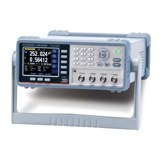
LCR Meter
Brand: GW Instek
|
Category: Measuring Instruments
|
Size: 2.61 MB
Table of Contents
-
Cleaning16
-
Overview18
-
Introduction18
-
Ranging19
-
Trigger Mode20
-
Test Signal21
-
List Sweep22
-
Files23
-
Key Lock23
-
Options23
-
Startup25
-
Front Panel25
-
Rear Panel26
-
Power On/Off26
-
Power on26
-
Power off26
-
Warm-Up Time27
-
Measure Key28
-
Setup Key56
-
Beep Feature68
-
Baud Rate76
-
Hand Shake77
-
Error Code78
-
Result79
-
Data Buffer79
-
Default Set80
-
FILE] Page82
-
Media]83
-
Connection88
-
Examples90
-
Example91
-
Terminator98
-
Disp:line103
-
Disp:page103
-
Function105
-
Level Subsystem109
-
Level:mode111
-
Aperture:rate112
-
Aperture:avg112
-
Fetch Subsystem113
-
Fetch113
-
Fetch:impedance114
-
Fetch:main114
-
Fetch:monitor114
-
Fetch:list115
-
Comparator:state117
-
Comparator:mode117
-
Comparator:aux117
-
Comparator:bins118
-
Comparator:slim119
-
Comparator:beep119
-
Comparator:open120
-
LIST Subsystem120
-
List:parameter120
-
List:stat121
-
List:band121
-
Correction:open122
-
Correction:short123
-
Trigger:source125
-
Trigger:delay126
-
BIAS Subsystem126
-
FILE Subsystem127
-
File127
-
File:save127
-
File:load127
-
File:delete128
-
Error Subsystem128
-
Error128
-
SYSTEM Subsystem128
-
System:shakehand128
-
System:code129
-
System:keylock129
-
System:result129
-
Common Commands129
-
Idn129
-
Trg130
-
Sav130
-
Rcl130
-
Specification131
-
Dimensions135
-
Accuracy136
-
Accuracy137
-
Accuracy for D137
-
Accuracy for Q138
-
Accuracy for138
Advertisement
GW Instek LCR-6300 User Manual (143 pages)
Brand: GW Instek
|
Category: Measuring Instruments
|
Size: 3.31 MB
Table of Contents
-
2 Overview
18-
Introduction18
-
-
Ranging19
-
Trigger Mode20
-
Test Signal20
-
Options22
-
-
3 Startup
25 -
-
-
5 Setup Key
55-
-
Beep Feature67
-
-
Connection87
-
9 Examples
89 -
-
Terminator97
-
-
Level Subsystem108
-
-
Aperture:rate111
-
Aperture:avg111
-
-
Fetch Subsystem112
-
Fetch112
-
Fetch:impedance113
-
Fetch:main113
-
Fetch:monitor113
-
Fetch:list114
-
-
-
Comparator:state115
-
Comparator:mode116
-
Comparator:aux116
-
Comparator:bins116
-
Comparator:slim117
-
Comparator:beep118
-
Comparator:open118
-
-
LIST Subsystem119
-
List:parameter119
-
List:stat119
-
List:band120
-
-
-
Trigger:source125
-
Trigger:delay125
-
BIAS Subsystem126
-
FILE Subsystem127
-
File127
-
File:save127
-
File:load127
-
File:delete128
-
-
Error Subsystem128
-
Error128
-
-
SYSTEM Subsystem128
-
System:shakehand128
-
System:code128
-
System:keylock129
-
System:result129
-
-
Common Commands129
-
-
12 Specification
131-
Dimensions135
-
13 Accuracy
136-
Accuracy137
-
Accuracy for D137
-
Accuracy for Q138
-
Accuracy for138
-
Accuracy for Rp138
-
Accuracy for Rs139
-