
Related Manuals for GW Instek LCR-6300


Summary of Contents for GW Instek LCR-6300
- Page 1 LCR Meter LCR-6300/6200/6100/6020/6002 User's Guide VERSION: 1.03 ISO-9001 CERTIFIED MANUFACTURER...
- Page 2 This manual contains proprietary information, which is protected by copyright. All rights are reserved. No part of this manual may be photocopied, reproduced or translated to another language without prior written consent of the Good Will company. The information in this manual was correct at the time of printing.
-
Page 3: Safety Summary
LCR-6000 Series User Manual Safety Summary Warning Dangerous When you notice any of the unusual conditions listed below, immediately terminate operation and disconnect the power cable. Please contact the GWINSTEK service center representative for repair of the instrument. If you continue to operate without repairing the instrument, there is a potential fire or shock hazard for operators. - Page 4 Safety Summary Operating personnel must not remove instrument Keep Away From Live covers. Component replacement and internal Circuits adjustments must be made by qualified maintenance personnel. Do not replace components with the power cable connected. Under certain conditions, dangerous voltages may exist even with the power cable is removed.
-
Page 5: Table Of Contents
LCR-6000 Series User Manual Table of Contents Safety Summary ..................i Table of Contents ..................1 Table of Figures ..................8 List of Tables ....................10 1. UNPACKING AND PREPERATION ...........11 Incoming Inspection ................ 11 Environmental Requirements ............12 Cleaning .................... 12 How to Remove the Handle ............ - Page 6 Table of Contents 2.5.2 Key Lock ................... 19 2.5.3 RS‐232 ..................19 Options ..................... 19 2.6.1 USB host port ................19 2.6.2 DC Bias Voltage ................ 20 3. STARTUP....................21 Front panel ..................21 Rear Panel ..................22 Power On/Off ................. 22 3.3.1 Power On ..................
- Page 7 LCR-6000 Series User Manual 4.4.1 Trigger Mode [TRIG] .............. 46 4.4.2 Test Mode [MODE] ..............47 4.4.3 Range Mode [RANGE] ............48 4.4.4 Measurement log [LOG] ............48 [ENLARGE DISPLAY ] Page ............50 4.5.1 Enlarge Display ................ 50 4.5.2 Direct Comparison Function ..........
- Page 8 Table of Contents [SYSTEM CONFIG] Page ............. 69 6.1.1 Setting the system date and time ..........70 6.1.2 Account Setting................. 71 6.1.3 KEY BEEP Setting ..............72 6.1.4 RS-232 baud rate ..............72 6.1.5 Hand Shake ................73 6.1.6 Error Code ................74 6.1.7 Result ..................
- Page 9 LCR-6000 Series User Manual 11.4 Header and Parameters ..............96 11.5 Command Reference ............... 98 11.6 DISPlay Subsystem ................99 11.6.1 DISP:LINE ................99 11.6.2 DISP:PAGE ................99 11.7 FUNCtion Subsystem ..............101 11.7.1 FUNCtion ................101 11.7.2 FUNCtion:IMPedance:AUTO ..........102 11.7.3 FUNCtion:IMPedance:RANGe ...........
- Page 10 Table of Contents 11.11.4 COMParator:BINS ............114 11.11.5 COMParator:TOLerance:NOMinal......114 11.11.6 COMParator:TOLerance:BIN ........114 11.11.7 COMParator:SLIM ............115 11.11.8 COMParator:BEEP ............115 11.11.9 COMParator:OPEN ............116 11.12 LIST Subsystem ................116 11.12.1 LIST:PARAmeter ............116 11.12.2 LIST:STAT ..............117 11.12.3 LIST:BAND ..............
- Page 11 LCR-6000 Series User Manual 11.18.2 SYSTem:CODE ............. 125 11.18.3 SYSTem:KEYLock ............125 11.18.4 SYSTem:RESult.............. 125 11.19 Common Commands ..............125 11.19.1 *IDN? ................125 11.19.2 *TRG ................126 11.19.3 *SAV ................126 11.19.4 *RCL ................126 12. SPECIFICATION ................127 12.1 General Specification ..............
-
Page 12: Table Of Figures
Table of Contents Table of Figures Figure 1-1 How to remove the handle ............. 13 Figure 2-1 Disk Ready ..................20 Figure 2-2 Screen Saved ..................20 Figure 3-1 Front panel ..................21 Figure 3-2 Rear Panel ..................22 Figure 3-3 Connect to DUT ................23 Figure 4-1 [MEAS DISPLAY] Page .............. - Page 13 LCR-6000 Series User Manual Figure 11-8 COMParator Subsystem Command Tree ........112 Figure 11-9 LIST Subsystem Command Tree ..........116 Figure 11-10 CORRection Subsystem Command Tree ........118 Figure 11-11 TRIGger Subsystem Command Tree .......... 121 Figure 11-12 BIAS Subsystem Command Tree ..........122 Figure 11-13 FILE Subsystem Command Tree ..........
-
Page 14: List Of Tables
HOLD state............. 28 Table 4-7 Frequency range and resolution ............. 29 Table 4-8 LCR-6300’s predefined test frequencies that can be selected by using INCR+/DECR‐ ..............30 Table 4-9 LCR-6200’s predefined test frequencies that can be selected by using INCR+/DECR‐... -
Page 15: Unpacking And Preperation
LCR-6000 Series User Manual NPACKING AND PREPERATION This chapter describes how to set up and start the LCR-6000 Series LCR Meter. Incoming Inspection Environmental Requirements Cleaning How to Remove the Handle 1.1 Incoming Inspection After you receive the instrument, perform the following checks during unpacking according to the following procedure: If the external face of the instrument (such as... -
Page 16: Environmental Requirements
UNPACKING AND PREPERATION If an abnormality is detected, contact the company and Note transport the meter to your nearest GW INSTEK Instruments sales or service office. Save the packing box, shock-absorbing material, and packaged items as you received them in case you need to mail the instrument to an authorized GW Instek distributor or service center. -
Page 17: How To Remove The Handle
LCR-6000 Series User Manual 1.4 How to Remove the Handle A handle kit is attached to the LCR-6000 Series: Figure 1-1 How to remove the handle Retracted Carrying Position Extended Remove Handle (Lift the handle perpendicular to the unit while pulling it in the direction of 1.) -
Page 18: Overview
2.1 Introduction Thank you for purchasing an LCR-6000 Series LCR meter. The GW INSTEK LCR-6000 Series is a general-purpose LCR meter for incoming inspection of components, quality control, and laboratory use. The LCR-6000 Series is used for evaluating LCR... -
Page 19: Main Specifications And Features
LCR-6000 Series User Manual 2.2 Main Specifications and Features 2.2.1 Test Function Cs-Rs, Cs-D, Cp-Rp, Cp-D, Lp-Rp, Lp-Q, Ls-Rs, Ls-Q, Rs-Q, Rp-Q, R-X, DCR, Z-θr, Z-θd, Z-D, Z-Q 2.2.2 Equivalent Circuit Serial and Parallel Table 2-1 Equivalent Circuit Circuit Dissipation Conversion Factor D=2π... -
Page 20: Trigger Mode
Overview 2.2.5 Trigger Mode Includes Internal, Manual, External and Bus Trigger. 2.2.6 Basic Accuracy 0.05%@SLOW/MED 0.1%@FAST 2.2.7 Display Range Table 2-2 Display Range Parameter Display Range 0.00001uH ~ 9999.99H 0.00001pF ~ 9999.99mF R, X, |Z| 0.00001Ω ~ 99.9999MΩ G, B, |Y| 0.01nS ~ 999.999S 0.00001 ~ 9.99999 0.00001 ~ 99999.9... -
Page 21: Test Signal
LCR-6000 Series User Manual 2.3 Test Signal 2.3.1 Test Signal Frequency LCR-6300: 10Hz~300kHz LCR-6200: 10Hz~200kHz LCR-6100: 10Hz~100kHz LCR-6020: 10Hz~20kHz LCR-6002: 10Hz~2kHz Frequency Accuracy: ±0.01% 2.3.2 Test Signal Level 10.00mV- 2.00V (±10%) CV mode:10.00mV- 2.00V(±6%) 100.0uA- 20.00mA (±10%) CC mode:100.0uA- 20.00mA(±6%) @2VMax DCR: ±1V(2Vpp), Square wave, 3Hz up... -
Page 22: Main Functions
Overview 2.4 Main Functions 2.4.1 Correction Function OPEN/SHORT correction: Eliminates measurement errors due to stray parasitic impedance in the test fixtures. 2.4.2 Comparator Function (Sorting) Bin sort The primary parameter can be sorted into BIN1-BIN9, AUX, OUT and HI/IN/LO for each of the primary measurement parameters. -
Page 23: Measurement Assistance Functions
LCR-6000 Series User Manual 2.5 Measurement Assistance Functions 2.5.1 Files Up to 10 setup conditions can be written to/read from the built-in non-volatile memory. 2.5.2 Key Lock The front panel keys can be locked. 2.5.3 RS‐232 Complies with SCPI. 2.6 Options 2.6.1 USB host port Universal serial bus jack, type-A (4 contact positions, contact 1 is on your left);... -
Page 24: Dc Bias Voltage
Overview Figure 2-1 Disk Ready If the keypad is not needed to enter a numeric value, a screenshot of the meter’s LCD display can be captured and saved to the USB disk by depressing the Enter key. If the screen shot is saved successfully, “Screen saved.” will be shown in the message area at the bottom of the screen. -
Page 25: Startup
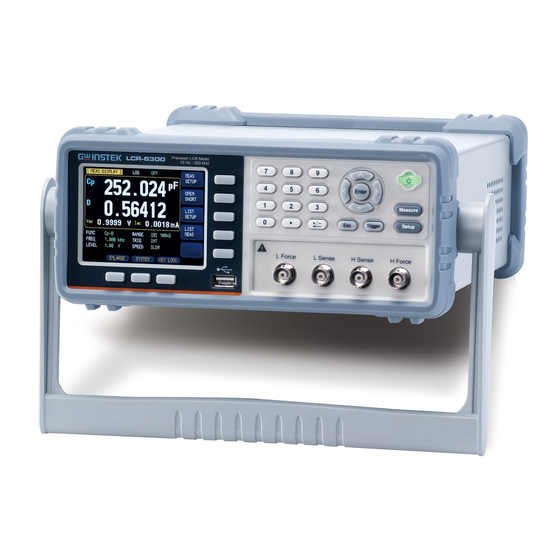
LCR-6000 Series User Manual TARTUP This chapter describes names and functions of the front panel, rear panel, and screen display and provides the basic procedures for operating the LCR- 6000 Series. Front panel summary Rear panel summary Power On/Off ... -
Page 26: Rear Panel
Startup Setup Key BNC Terminal Trigger Key ESC Key USB Disk Port (USB-Host) System Soft-key 3.2 Rear Panel Figure 3-2 Rear Panel Table 3-2 Rear panel description Description Power Cable Receptacle(Outlet) (to LINE) Frame Terminal RS-232C Interface Handler Interface 3.3 Power On/Off 3.3.1 Power On Press the power key for at least 2 seconds. -
Page 27: Warm-Up Time
LCR-6000 Series User Manual 3.4 Warm‐up Time LCR-6000 Series is ready to be used as soon as the power-up sequence has completed. However, to achieve the specification accuracy, first warm up the instrument for 30 minutes. 3.5 Connect to the Device Under Test (DUT) The LCR-6000 Series uses a four terminal measurement configuration that provides easy, accurate and stable... -
Page 28: Measure Key
Measure Key EASURE KEY This section includes the following information: MEAS DISPLAY page OPEN/SHORT page LIST SETUP page LIST MEAS page 4.1 [MEAS DISPLAY] Page When the [Measure] key is pressed, the [MEAS DISPLAY] page appears. The following measurement controls can be set. -
Page 29: Measurement Function [Func]
LCR-6000 Series User Manual Figure 4-1 [MEAS DISPLAY] Page 4.1.1 Measurement Function [FUNC] The LCR-6000 Series simultaneously measures four components of complex impedance (parameters) in a measurement cycle. These include a primary parameter, a secondary parameter and two monitor parameters. NOTE The monitor parameters can be set in the [SETUP] page. -
Page 30: Table 4-3 Measurement And Monitor Parameter Descriptions
Measure Key Table 4-3 Measurement and Monitor parameter descriptions Parameter Description Capacitance value measured using the series equivalent circuit model Capacitance value measured using the parallel equivalent circuit model Inductance value measured using the series equivalent circuit model Inductance value measured using the parallel equivalent circuit model Equivalent series resistance measured using the series equivalent circuit... -
Page 31: Impedance Range [Range]
LCR-6000 Series User Manual 4.1.2 Impedance Range [RANGE] Impedance range mode To achieve the best measurement result, it is recommended to set the impedance range mode to “Auto range”. When using “Hold range”, errors in measurement results may occur if the measured value exceeds the full scale of the selected range. -
Page 32: Table 4-5 Effective Measurement Range For The Impedance Range When In Hold State
Measure Key Table 4-5 Effective measurement range for the impedance range when in HOLD state. Range Impedance Effective measurement range range 10Ω 0 - 10Ω 30Ω 10Ω-100Ω 100Ω 100Ω-316Ω 300Ω 316Ω-1kΩ 1kΩ 1kΩ-3.16kΩ 3kΩ 3.16kΩ-10kΩ 10kΩ 10kΩ-31.6kΩ 30kΩ 31.6kΩ-100kΩ () 100kΩ... -
Page 33: Test Frequency [Freq]
INCR + Increments the impedance range in the HOLD mode DECR - Decrements the impedance range in the HOLD mode 4.1.3 Test Frequency [FREQ] LCR-6300: 10Hz~300kHz LCR-6200: 10Hz~200kHz LCR-6100: 10Hz~100kHz LCR-6020: 10Hz~20kHz LCR-6002: 10Hz~2kHz Table 4-7 Frequency range and resolution... -
Page 34: Table 4-8 Lcr-6300'S Predefined Test Frequencies That Can Be Selected By Using Incr+/Decr
Be used to select between predefined measuring frequencies. DECR - Refer to Table 4-8, Table 4-9, Table 4-10, Table 4-11, Table 4-12. Table 4-8 LCR-6300’s predefined test frequencies that can be selected by using INCR+/DECR‐ INCR+/DECR- 10Hz 50Hz 60Hz 100Hz... -
Page 35: Trigger Mode [Trig]
LCR-6000 Series User Manual Table 4-12 LCR-6002’s predefined test frequencies that can be selected by using INCR+/DECR‐ INCR+/DECR- 10Hz 50Hz 60Hz 100Hz 120Hz 1kHz 2kHz 4.1.4 Trigger Mode [TRIG] LCR-6000 Series supports four trigger modes: INT (internal), EXT (external), MAN (manual) and BUS (RS- 232). -
Page 36: Test Signal Voltage/Current Level [Level]
Measure Key 4.1.5 Test Signal Voltage/Current Level [LEVEL] The LCR-6000 Series’ test signal voltage/current level can be set as the effective value (RMS value) of a sine wave of the test frequency from the unit’s internal oscillator. When a constant voltage or current level measurement is performed, an asterisk mark (*) appears at the end of the LEVEL display. -
Page 37: Measurement Speed [Speed]
LCR-6000 Series User Manual 4.1.6 Measurement Speed [SPEED] SLOW, MED and FAST can be selected for LCR-6000 Series. SLOW mode will result in more stable and accurate measurement results. Procedure for setting measurement speed mode Step 1. Press the [Measure] key. Step 2. -
Page 38: Measurement Log [Log]
Measure Key 26.5 88.5 24.5 100k 88.5 24.5 300k 88.5 24.5 4.1.7 Measurement log [LOG] The LCR-6000 has an internal data buffer that record up to 10000 measurement readings. These readings can be saved to an external USB drive in a .csv file format. These readings can then be opened on a PC using software such as Windows Excel. - Page 39 LCR-6000 Series User Manual SAVE TO USB Saves the recorded readings in the buffer to an external USB flash drive. The internal buffer is cleared after this operation. CLEAR Clears the internal buffer. BUFFER SAVE & STOP Stops the recording and saves the recorded readings in the internal buffer to an external USB flash drive.
- Page 40 Measure Key Before saving the recorded readings in the internal buffer to the external USB flash drive, remember to plug the external USB drive into the USB port on the front panel. The recorded readings will be saved in a subdirectory named MEAS DATA, whose parent directory will have the same name as the LCR-6000 model being used.
-
Page 41: Open/Short] Page
LCR-6000 Series User Manual 4.2 [OPEN/SHORT] Page When you press the [Measure] key and the [OPEN SHORT] soft-key, the [ OPEN SHORT ] page appears. In this page, the OPEN/SHORT/SPOT correction for correcting the stray admittance and residual impedances can be performed. The OPEN and SHORT function performs open or short correction over a range of fixed trimming points. -
Page 42: Open Correction [Open]
Measure Key 4.2.1 Open Correction [OPEN] The LCR-6000 Series’ OPEN correction capability cancels errors due to the stray admittance (G, B) in parallel with the device under test (Refer to Figure 4-3). Figure 4-3 Stray Admittance The OPEN correction data is taken at all preset frequency points, independent of the test frequency you set. -
Page 43: Short Correction [Short]
LCR-6000 Series User Manual During the measurement, an “LCR OPEN measurement in progress” dialog message is shown on the display. When the measurement has finished, “Correction finished” is displayed. During the measurement, you can press the [ABORT] soft-key to abort the OPEN correction. Step 7. -
Page 44: Spot Correction
Measure Key Step 4. Press the [MEAS SHORT] or [DCR SHORT] soft-key, a dialog message, “Short-circuit the test terminals”, will appear. Step 5. Connect the test fixture to the BNC terminals and short-circuit the test terminals. Step 6. Press the [OK] soft-key. The LCR-6000 measures the short impedances (inductances and resistance) at the all test frequency points. - Page 45 LCR-6000 Series User Manual Step 4. Press the [MEAS OPEN] soft-key. A dialog message, “Open-circuit the test terminals”, will appear. Step 5. Connect the test fixture to the BNC terminals. Do not connect the DUT to the test fixture. Step 6. Press the [OK] soft-key.
-
Page 46: List Setup] Page
Measure Key 4.3 [LIST SETUP] Page Press the [Measure] key and press the [LIST SETUP] soft-key to open the [LIST SETUP] page. The List Measure feature can perform automatic sweep measurements by sweeping the frequency or signal level through a maximum 10 list points. Before using the List Measure feature, you have to configure the list setup. -
Page 47: Test Mode [Mode]
LCR-6000 Series User Manual 4.3.2 Test Mode [MODE] The [LIST MEAS] page will execute a list of up to 10 swept frequency or amplitude tests. When [MODE] is set to SEQ and [TRIG] is set to MAN, the [LIST MEAS] function will automatically execute each test step on the list in sequence until the last step is executed. -
Page 48: List Measurement Parameters
Measure Key 4.3.3 List Measurement Parameters The list parameter used for the list measurement can be the measurement frequency or the signal level [V/A]. Use the list point field to specify the list measurement parameter. To specify the list sweep measurement parameter Step 1. - Page 49 LCR-6000 Series User Manual Step 5. Enter the list point value (maybe the frequency value or the signal level voltage/current value). When you enter the frequency value, the soft-key labels change to unit labels (Hz, kHz). When you enter the signal level voltage value, you don’t need to enter units.
-
Page 50: List Meas] Page
Measure Key 4.4 [LIST MEAS] Page The [LIST MEAS] page will appear when you press the [Measure] key and then the [LIST MEAS] soft-key. Figure 4-6 [LIST MEAS] Page On the [LIST MEAS] page, the list points are swept and the measurement results are compared to the limits. -
Page 51: Test Mode [Mode]
LCR-6000 Series User Manual Trigger mode When entering LIST MEAS for the first time, the system will set Trig Mode to MAN and automatically performs a measurement. Trig Mode Function Internal Trigger. All ten list points are swept continuous. Manual Trigger. Each time the instrument is triggered by [Trig] key, the list points are swept one by one. -
Page 52: Range Mode [Range]
Measure Key There are 4 available trigger modes in the [LIST MEAS] page. Trigger Modes Function Trigger by the meter’s internal trigger source. Trigger by pressing the trigger button. Trigger by sending a signal to the trigger pin on the handler interface. Trigger by the RS-232 port. - Page 53 LCR-6000 Series User Manual Soft-key Function SAVE & STOP Stops the recording and saves the recorded readings in the internal buffer to an external USB flash drive. The internal buffer will be cleared after the save operation. If an external USB flash drive is not plugged in, the meter will not stop the ongoing recording.
-
Page 54: Enlarge Display] Page
Measure Key 4.5 [ENLARGE DISPLAY] Page Only four measurement values will be shown in this simplified display mode: The primary measurement parameters, the secondary measurement parameters and two monitored parameters such as △, △%, Iac or Vac, etc. 4.5.1 Enlarge Display Press the ENLARGE soft-key in the [MEAS DISPLAY] to enter the [ENLARGE DISPLAY] mode (simplified display mode);... -
Page 55: Direct Comparison Function
LCR-6000 Series User Manual Figure 4-7 [ENLARGE DISPLAY] Page 4.5.2 Direct Comparison Function The Direct Comparison function can be turned on in the [BIN SETUP] page. When the number of bins is set to 1 in the [BIN SETUP] page, the Direct Comparison function will be activated for the [ENLARGE DISPLAY] mode. -
Page 56: Setup Key
Setup Key ETUP KEY This section includes the following information: MEAS SETUP page BIN SETUP page BIN MEAS page BIN COUNT page Every time or everywhere you can press the [Setup] key to open the [MEAS SETUP] page. - Page 57 LCR-6000 Series User Manual In the [MEAS SETUP] Page, you can configure each of the following measurement controls with the cursor placed in the corresponding field. Measurement Function [FUNC] Impedance range [RANGE] Test Frequency [FREQ] Trigger Mode [TRIG] ...
-
Page 58: Source Output Impedance [Src Res]
Setup Key 5.1.1 Source Output Impedance [SRC RES] The Source output impedance can be set to 30Ω, 50Ω or 100Ω. If you use LCR-6000 Series to test a smaller inductor, please use 30Ω. If you need to compare test results with Keysight E4980A, select 100Ω. -
Page 59: Dc Bias Voltage [Bias]
LCR-6000 Series User Manual 5.1.3 DC Bias Voltage [BIAS] This function will apply a DC bias voltage onto the DUT while LCR meter is performing its AC measurement on the DUT. The settable DC bias voltage range is from - 2.5V ~ 2.5V. -
Page 60: Monitor 1 And Monitor 2 [Mon 1][Mon 2]
Setup Key To set up the Auto LCZ Function Step 1. Press the [Setup] key Step 2. Use the cursor key to select [AUTO LCZ] field Step 3. Use the soft-keys to turn on/off the Auto LCZ Function. Soft-key Function Turn off the Auto LCZ Function Turn on the Auto LCZ Function. -
Page 61: Measurement Delay [Delay]
LCR-6000 Series User Manual θd Phase angle Resistance (=Rs) Reactance Conductance Sustenance Absolute value of admittance 5.1.6 Measurement Delay [DELAY] This setting decides how long the meter will wait to commence a measurement after the trigger signal is received. Settable range: 0ms to 60s. 5.1.7 AUTO LEVEL CONTROL [ALC] The automatic level control (ALC) feature adjusts the voltage across the DUT or the current through the DUT... -
Page 62: Bin Setup] Page
Setup Key 5.2 [BIN SETUP] Page Press [Setup] key and press the [BIN SETUP] soft-key to open [BIN SETUP] page. This page allows you to configure the LCR-6000 Series’ built-in comparator. The built-in comparator can sort DUTs into a maximum of 10 levels (BIN1 through BIN9 and OUT) using up to nine sets of primary parameter limits along with one set of secondary parameter limits. -
Page 63: Measurement Function [Func]
LCR-6000 Series User Manual Figure 5-2 [BIN SETUP] Page 5.2.1 Measurement Function [FUNC] The LCR-6000 Series simultaneously measures four components of the complex impedance (parameters) in a measurement cycle. These include primary parameter, secondary parameter and two monitor parameters. Please refer to the 4.1 [MEAS DISPLAY] Page section on 24 for details. -
Page 64: Figure 5-3 Page Comparator Workflow
Setup Key Figure 5-3 Page Comparator Workflow Sorting Start COMP=ON BIN1 <Primary<BIN1 …. BIN9 <Primary<BIN9 AUX=ON AUX=ON Lower<Secondary<Upper Lower<Secondary<Upper Display: OUT AUX NG Display: BIN1-9 AUX NG Display: BIN1-9 OK Display: OUT NG Output: NG Output: NG Output: BIN_1 or BIN_2 … Output: NG S_OVER S_OVER... -
Page 65: Auxiliary Bin [Aux]
LCR-6000 Series User Manual 5.2.3 Auxiliary Bin [AUX] After AUX is turned on, DUTs that do not fall within the primary parameter limit values are sorted as OUT. In addition, DUTs that fall within the primary parameter limits but are out of the secondary parameter limits are sorted into the auxiliary (AUX) bin. -
Page 66: Figure 5-4 Absolute Mode
Setup Key and PER compare modes. Use the number keys to enter the value and the unit. Absolute mode[ABS] Absolute value (Δ) = UNKNOWN value – nominal value Figure 5-4 Absolute mode Includes the point ● ○ Excludes the point Percentage mode [PER] Deviation percentages (%) = Absolute value (Δ)/nominal value ×... -
Page 67: Figure 5-6 Sequential Mode
LCR-6000 Series User Manual Sequential mode[SEQ] Figure 5-6 Sequential mode Includes the point ● ○ Excludes the point In Sequential mode, the comparison limit values are based on the absolute value of the measurement. The nominal value does not need to participate in operation. To set up the comparator limit mode Step 1. -
Page 68: Nominal Value For Tolerance Mode
Setup Key 5.2.5 Nominal value for tolerance mode You must configure the nominal value when you use tolerance mode as the limit mode for the primary parameter. In sequential mode the nominal value does not affect sorting. In sequential mode, you do not need to configure the nominal value. -
Page 69: Lower And Upper Limits
LCR-6000 Series User Manual Soft-key Function 1-BINS Set to 1 bin 2-BINS Set to 2 bins 3-BINS Set to 3 bins 4-BINS Set to 4 bins 5-BINS Set to 5 bins 6-BINS Set to 6 bins 7-BINS Set to 7 bins 8-BINS Set to 8 bins 9-BINS... -
Page 70: Comparator Function On/Off
Setup Key Figure 5-7 [BIN MEAS] Page This page provides the following information: FUNC, RANGE, FREQ, LEVEL, TRIG, LEVEL, SPEED: These conditions can be set from [MEAS DISPLAY] page. Comparator function ON/OFF [COMP]. Auxiliary bin ON/OFF [AUX]. 5.3.1 Comparator Function ON/OFF LCR-6000 built-in comparator can sort DUTs into a maximum of 10 bins (BIN1 to BIN9 and OUT) using a... -
Page 71: Auxiliary Bin [Aux]
LCR-6000 Series User Manual Soft-key Function Turns OFF the COMP function Turns ON the COMP function 5.3.2 Auxiliary Bin [AUX] After AUX is turned on, DUTs that do not fall within the primary parameter limit values are sorted as OUT. In addition, DUTs that fall within the primary parameter limits but out of the secondary parameter limits are sorted into the auxiliary (AUX) bin. -
Page 72: Counter Function [Count]
Setup Key 5.4.1 Counter Function [COUNT] The number of DUTs sorted into each bin is counted while the unit sorts the DUTs into the appropriate bins using the comparator function. When the maximum count of 99999999 is reached, the counting operation stops and the overflow message “--------”... -
Page 73: System Configurations
LCR-6000 Series User Manual YSTEM CONFIGURATIONS This section includes the following information: SYSTEM CONFIG page SYSTEM INFO page SYSTEM SERVICE page 6.1 [SYSTEM CONFIG] Page When the [Measure] or [Setup] key is pressed, followed by the [SYSTEM] bottom soft-key, the [SYSTEM CONFIG] page appears. -
Page 74: Setting The System Date And Time
System Configurations Figure 6-1 [SYSTEM CONFIG] Page 6.1.1 Setting the system date and time LCR-6000 Series features a built-in 24-hour clock. To change the date Step 1. Press the [Measure] or [Setup] key. Step 2. Press the [SYSTEM] bottom soft-key. Step 3. -
Page 75: Account Setting
LCR-6000 Series User Manual Soft-key Function HOUR INCR+ Increases the hour in steps of 1. HOUR DECR- Decreases the hour in steps of 1. MINUTE INCR+ Increases the minute in steps of 1. MINUTE INCR- Decreases the minute in steps of 1. SECOND DECR+ Increases the second in steps of 1. -
Page 76: Key Beep Setting
System Configurations If you forget your password, please contact your local NOTE GW Instek distributor or GWInstek at www.gwinstek.com / marketing@goodwill.com.tw. 6.1.3 KEY BEEP Setting Key tone settings. To set up the beep feature Step 1. Press the [Measure] or [Setup] key. -
Page 77: Hand Shake
PC first before returning the result string of the command. Example: PC sends idn? The meter returns: idn? LCR-6300 RevC1.0 To set up the Hand Shake feature Step 1. Press the [Measure] or [Setup] key. -
Page 78: Error Code
System Configurations 6.1.6 Error Code If the error code setting is set to on, the meter will return error codes if the wrong command or an invalid command is received to help you to debug your control program. "*E00", //No error "*E01", //"Bad command", "*E02", //"Parameter error", "*E03", //"Missing parameter",... -
Page 79: Result
LCR-6000 Series User Manual 6.1.7 Result If the Result setting it set to Auto, the meter will automatically send out the measurement results each time a test is finished; this setting is convenient especially when the meter is working with a sorting machine. The meter will start a test after receiving the trigger signal and then returns the test result to the sorting machine without the need to receive a ‘fetch?’... -
Page 80: Default Set
System Configurations 6.1.9 DEFAULT SET To reset setting values (MEAS SETUP) and offset values (OPEN SHORT) to factory default, use the DEFAULT SET setting. The device can be quickly restored to its factory settings. Default settings: (MEAS SETUP): FUNC: Cp-D FREQ: 1kHz LEVEL: 1V RANGE: AUTO... -
Page 81: System Info] Page
LCR-6000 Series User Manual 6.2 [SYSTEM INFO] Page When the [Measure] or [Setup] key is pressed followed by [SYSTEM] bottom soft-key, and then the [SYSTEM INFO] soft-key, the [SYSTEM INFO] page appears. There are no configurable options in the [SYSTEM INFO] page. Figure 6-2 [SYSTEM INFO] Page... -
Page 82: File Operation
File Operation ILE OPERATION This chapter provides information on the file operation of the LCR-6000 Series. You can save up to 10 files into the internal non-volatile memory. 7.1 [FILE] Page When the [Setup] key is pressed followed by the [FILE] bottom soft-key, the [FILE] page appears. -
Page 83: Media]
LCR-6000 Series User Manual 7.1.1 [MEDIA] The Media field is used to select the media source from either the meter’s internal memory or an external USB flash drive. A maximum of up to 10 files can be accessed from either source. Step 1. -
Page 84: Auto Save Data To Last File [Auto Save]
File Operation 7.1.3 Auto save data to last file [AUTO SAVE] You can save the modified data into the last used file when the instrument power key is pressed. To turn on/off the AUTO SAVE function Step 1. Press the [Setup] key. Step 2. -
Page 85: Handler Interface
LCR-6000 Series User Manual ANDLER INTERFACE This chapter provides information about the LCR-6000 Series’ built-in handler interface. It includes: Pin Assignment Circuit Diagram Timing Chart The LCR-6000 Series’ built-in handler interface outputs signals that indicate the end of a measurement cycle, the result of bin sorting by the comparator. -
Page 86: Pin Assignment
Handler Interface 8.1 Pin Assignment Figure 8-1 Pin Assignment Output Pins Table 8-1 Handler Interface Signals ~ Output Pins Pin names Signal descriptions The sorting result is within bin1. O_BIN_1 Active low. The sorting result is within bin2. O_BIN_2 Active low. The sorting result is within bin3. -
Page 87: Table 8-2 Handler Interface Signals ~ Input Pins
LCR-6000 Series User Manual Over fail occurs on the secondary measurement parameter. Active O_S_OVER low. (The signal on this pin is available only after AUX is turned on.) Over fail occurs on the primary measurement parameter. Active O_P_OVER low. The logic state of this pin = O_P_HI OR O_P_LO. -
Page 88: Connection
Handler Interface 8.2 Connection Electrical parameters Interface power requirements: +12.4V~36VDC, 0.2A(Min). Output circuit: Built-in pull-up resistors are internally connected to the collector pin of the output transistors. The output pins are isolated by photocouplers. Input pins: Isolated by photocouplers. Warning: To avoid damaging the interface, ensure the external power does not exceed the +12.4~36V input range. -
Page 89: Timing Chart For Handler Interface
LCR-6000 Series User Manual Circuit of output pins Figure 8-3 Circuit of output pins (Bin sorting, Index, EOM) EXT.DCV R 4.99k OUTPUT Maximum sourcing current: 5mA. Maximum sinking current: 50mA 8.3 Timing Chart for Handler Interface Figure 8-4 Timing chart Table 8-4 Timing Definitions Time segment... -
Page 90: Examples
Examples XAMPLES This chapter covers basic measurement procedures as well as basic L, C, and R measurement theory. It also offers various measurement hints. After the descriptions of basic measurement procedures, practical measurement examples are shown using LCR-6000 Series. 9.1 Basic Measurement Procedure The following flow chart shows the basic procedures used to measure the impedance of capacitors, inductors, resistors, and other components. -
Page 91: Example
LCR-6000 Series User Manual Figure 9-1 Basic Measurement Procedure Start Setup measurement conditions: [FUNC] [LEVEL] [FREQ] Connect the test fixture CORRECTIONS OPEN TEST SHORT TEST Connect DUT Perform measurement 9.2 Example This paragraph describes a practical example of measuring a ceramic capacitor. The basic procedure flow to perform this measurement is the same as the Basic Measurement Procedure described previously. - Page 92 Examples Step 1. Turn the LCR-6000 Series ON. Step 2. Set up the measurement conditions by filling in the fields on the MEAS DISPLAY page. Move to the FUNC field using the cursor keys and choose Cs-D. Move to the FREQ field using the cursor ...
- Page 93 LCR-6000 Series User Manual Move to the SHORT TEST or SPOT field using the cursor keys. Connect the clips to a shorting bar as shown below: Press the [MEAS SHORT] soft-key and then the [OK] soft-key. Wait until the “Correction finished” message is displayed.
-
Page 94: Figure 9-2 Measurement Results
Examples performed continuously by the internal trigger, and the measured Cs and D values of the capacitors are displayed as shown below: Figure 9-2 Measurement results... -
Page 95: Remote Control
LCR-6000 Series User Manual EMOTE CONTROL This chapter provides the following information to remotely control the LCR- 6000 Series via the RS-232C: About RS-232 Select Baud Rate About SCPI LCR-6000 Series can use the RS-232 interface to communicate with the computer to complete all the instrument functions. -
Page 96: To Select Baud Rate
Remote Control Figure 10-2 PC - LCR-6000 Series connection uses a null modem connection Pin2 RxD Pin2 Pin3 TxD Pin3 Pin5 GND Pin5 Make sure the controller you connect to LCR-6000 Series also uses these settings. The RS-232 interface transfers data using: 8 data bits, 1 stop bit, no parity. -
Page 97: Scpi Language
LCR-6000 Series User Manual 10.3 SCPI Language Standard Commands for Programmable Instruments (SCPI) is fully supported by the RS-232 interface. LCR-6000 Series ONLY supports the SCPI Language. NOTE:... -
Page 98: Command Reference
Command Reference OMMAND REFERENCE 11.1 Terminator :The EOI line is asserted by New Line or ASCII Line Feed character. <NL> (Decimal 10, Hex 0x0A, or ASCII ‘\n’) 11.2 Notation Conventions and Definitions The following conventions and definitions are used in this chapter to describe RS-232 operation. -
Page 99: Figure 11-1 Command Tree Example
LCR-6000 Series User Manual Figure 11-1 Command Tree Example function :imp? :mon1 :imp :type {…} rang? Example: function:imp:type Cp-D function Subsystem Command Level 2 type Level 3 Cp-D Parameter The basic rules of the command tree are as follows. Letter case (upper and lower) is ignored. ... -
Page 100: Header And Parameters
Command Reference Command abbreviations: Every command and character parameter has at least two forms, a short form and a long form. In some cases they will be the same. The short form is obtained using the following rules. A) If the long form has four characters or less, the long form and short form are the same. -
Page 101: Table 11-1 Multiplier Mnemonics
LCR-6000 Series User Manual Headers can be of the long form or the short form. The long form allows easier understanding of the program code and the short form allows more efficient use of the computer. Parameters may be of two types as follows. (A) Character Data and String Data Character data consists of ASCII characters. -
Page 102: Command Reference
Command Reference 11.5 Command Reference All commands in this reference are fully explained and listed in the following functional command order. DISPlay Subsystem FUNCtion Subsystem FREQuency Subsystem VOLTage Subsystem APERture Subsystem FETCh Subsystem COMParator Subsystem ... -
Page 103: Display Subsystem
LCR-6000 Series User Manual 11.6 DISPlay Subsystem The DISP Subsystem command group sets the display page. Figure 11-2 Command Tree Example 11.6.1 DISP:LINE The :LINE command enters an arbitrary comment line of up to 30 ASCII characters in the comment field. Command Syntax DISP:LINE “<string>”... - Page 104 Command Reference COUNT. LISTMEAS [or LIST] Sets the display page to LIST MEAS. SETUP [or MSET] Sets the display page to MEAS SETUP. CORRECTION [or CSET] Sets the display page to CORRECTION. BINSETUP [or BSET] Sets the display page to BIN SETUP.
-
Page 105: Function Subsystem
LCR-6000 Series User Manual 11.7 FUNCtion Subsystem The FUNCtion subsystem command group sets the measurement function, the measurement range, monitors parameter control. Figure 11-3 FUNCtion Subsystem Tree FUNCtion {Cs-Rs,Cs-D, Cp-Rp,Cp-D, Lp-Rp,Lp-Q, Ls-Rs,Ls-Q, R-Q,R-X, Z-thr(Z-θr),Z-Thd(Z-θd) Z-D,Z-Q, DCR} :IMPedance {on,off,1,0} :AUTO <integer> :RANGe :DCR :AUTO... -
Page 106: Function:impedance:auto
Command Reference Query Response <function> Example SEND> FUNC?<NL> RET> Cp-D<NL> 11.7.2 FUNCtion:IMPedance:AUTO The FUNCtion:IMPedance:AUTO command sets the impedance’s LCZ Automatic selection. Command FUNC:IMPedance:AUTO {ON,OFF, 0,1} Syntax Example SEND> FUNC:IMP:AUTO ON<NL> Query Syntax FUNC:IMPedance:AUTO? Query Response {on,off}<NL> Example SEND> FUNC:IMP:AUTO?<NL> RET> off<NL>... -
Page 107: Function:range:auto
LCR-6000 Series User Manual Query Response <0-8><NL> Example SEND> FUNC:DCR:RANG?<NL> RET> 0<NL> 11.7.5 FUNCtion:RANGe:AUTO The FUNCtion:RANGe:AUTO command sets the auto range to ON or OFF. Command FUNC:RANGe:AUTO {off(hold),on(auto),NOMinal} Syntax Parameter Where, {off(hold),on(auto),NOMinal} is: off(or hold): Sets the auto range to off. on(or auto): Sets the auto range to on. -
Page 108: Figure 11-4 Freq Subsystem Command Tree
Command Reference FREQuency Subsystem The FREQuency command sets the oscillator frequency. The FREQuency? query returns the current test frequency setting. Figure 11-4 FREQ Subsystem Command Tree {value,MIN,MAX} [:CW] FREQuency Command FREQ[:CW] {<value>,MIN,MAX} Syntax Parameter Where, <value> Is the numeric data (NR1 integer, NR2fix float or NR3 floating point). -
Page 109: Level Subsystem
LCR-6000 Series User Manual 11.8 LEVel Subsystem The Level subsystem sets the oscillator’s output voltage/current level and source output impedance. Figure 11-5 LEVel Subsystem Command Tree 11.8.1 LEVel:VOLTage (=VOLTage[:LEVel]) The LEVel:VOLTage or VOLTage[:LEVel] command sets the oscillator’s output voltage level. Command LEVel:VOLTage {<value>,MIN,MAX} Syntax... -
Page 110: Level:current (=Current[:Level])
Command Reference 11.8.2 LEVel:CURRent (=CURRent[:LEVel]) The LEVel:CURRent or CURRent[:LEVel] command sets the oscillator’s output current level. Command LEVel:CURRent {<value>,MIN,MAX} Syntax or CURRent:LEVel {<value>,MIN,MAX} Parameter Where, <value> Is the numeric data (NR1, NR2 or NR3). MIN Sets to the minimum value of current. MAX Sets to the maximum value of current. -
Page 111: Level:alc (=Amplitude:alc)
LCR-6000 Series User Manual Note The suffix unit can’t be used with this command. This command CANNOT be used in LIST SWEEP. DISPLAY page and CORRECTION page. 11.8.4 LEVel:ALC (=AMPlitude:ALC) The LEVel:ALC or AMPlitude:ALC command enables the Automatic Level Control (ALC). -
Page 112: Aperture Subsystem
Command Reference 11.9 APERture Subsystem The APERture subsystem command sets the integration time of the ADC and the averaging rate. Figure 11-6 APERture Subsystem Command Tree {SLOW,MED,FAST} APERture <averaging rate value:NR1> Command APERture {SLOW,MED,FAST} Syntax APERture <value> SPEED(spd) {SLOW,MED,FAST} SPEED(spd) <value> Parameter Where, SLOW... -
Page 113: Fetch Subsystem
LCR-6000 Series User Manual 11.10 FETCh Subsystem The FETCh subsystem command group is a sensor-only command which retrieves the measurement data taken by measurement(s) initiated by a trigger, and places the data into the output buffer. Figure 11-7 FETCh Subsystem Command Tree IMPedance? FETCh MAIN? -
Page 114: Fetch:impedance
Command Reference 11.10.2 FETCh:IMPedance? The FETCh:IMPedance? query sets the latest measurement data of the primary parameter, secondary parameter, monitor1 and monitor2 results into the output buffer. Query Syntax FETCh:IMPedance? Query Response <NR3:primary value>,<NR3:secondary value>, <NR3:monitor1>,<NR3:monitor2>,<comparator result> Example SEND> FETC:IMP?<NL> RET> +2.61788e-11,+5.45442e-01,+3.88651e+05, +0.00000e+00,BIN1,AUX-OK, OK<NL>... -
Page 115: Fetch:list
LCR-6000 Series User Manual Example SEND> FETC:MON?<NL> RET> +3.88651e+05,+0.00000e+00<NL> (0: The monitor 2 is OFF) 11.10.6 FETCh:LIST? The FETCh:LIST? query sets the latest LIST measurement data of the primary parameters, secondary parameters and comparator results into the output buffer. Only applicable when in the [LIST MEAS] page view. Query Syntax FETCh:LIST? Query Response... -
Page 116: Comparator Subsystem
Command Reference 11.11 COMParator Subsystem The COMParator subsystem command group sets the comparator function, including its ON/OFF setting, limit mode, and limit values. Figure 11-8 COMParator Subsystem Command Tree {ON,OFF} :S TATe COMParator {ABS,PER,SEQ} :MODE {ON,OFF} :AUX {1 to 9} :BINS <value>... -
Page 117: Comparator:state
LCR-6000 Series User Manual 11.11.1 COMParator:STATe The COMParator:STATe command sets the comparator function to ON or OFF. Command COMParator:STATe {ON,OFF,1,0} Syntax Parameter Where, ON or 1 Sets the comparator to ON OFF or 0 Sets the comparator to OFF Example SEND>... -
Page 118: Comparator:bins
Command Reference Example SEND> COMP:AUX?<NL> RET> on<NL> 11.11.4 COMParator:BINS The COMParator:BINS command sets the total number of bins. Command COMParator:BINS <value> Syntax Parameter Where,{value} is: NR1 (1 to 9) Example SEND> COMP:BINS 3<NL> Query Syntax COMParator:BINS? Query Response <NR1> (1 to 9) Example SEND>... -
Page 119: Comparator:slim
LCR-6000 Series User Manual Query Syntax COMParator:TOLerance:BIN? <n> Parameter Where,<n> is: NR1 (1 to 9): Bin number Query Response <NR3:low limit>,<NR3:high limit> Example SEND> COMP:TOL:BIN? 2<NL> RET> 1.00000e-06,2.00000E-6<NL> 11.11.7 COMParator:SLIM The COMParator:SLIM or COMParator:secondary command sets the LOW/HIGH limit values for the secondary parameter. Command COMParator:SLIM <low value>,<high value>... -
Page 120: Comparator:open
Command Reference 11.11.9 COMParator:OPEN The :COMParator:OPEN command selects the open condition for main parameter. Command COMParator:OPEN {OFF,2,5,10,20,50} Syntax Parameter Where, Turns the beeper off. 2,5,10,20,50 The percent range value Example SEND> COMP:OPEN 2<NL> Query Syntax COMParator:OPEN? Query Response {OFF,2,5,10,20,50} Example SEND>... -
Page 121: List:stat
LCR-6000 Series User Manual Query Response {FREQ,VOLT,CURR} Example SEND> LIST:PARA?<NL> RET> FREQ<NL> 11.12.2 LIST:STAT The LIST:STAT command turns on/off the specified sweep point. Command LIST:STAT <n>,{ON,OFF,1,0} Syntax Parameter Where,<n> is: NR1(1 to 10): List sweep point ON or 1 Set this point to ON OFF or 0 Set this point to OFF Example SEND>... -
Page 122: Correction Subsystem
Command Reference Parameter Where,<n> is: NR1(1 to 10): List sweep point Query Response {on,off},<point value>,{A,B,- },<NR3:low>,<NR4:high> Example SEND> LIST:BAND? 1<NL> RET> on,1.00000e+03,A,1.000000E-9,2.000000E- 9<NL> 11.13 CORRection Subsystem The CORRection subsystem command group sets the correction function, including the OPEN, SHORT and LOAD correction settings. Note The CORRection subsystem CANNOT work in [LIST MEAS] page. -
Page 123: Correction:open:state
LCR-6000 Series User Manual 11.13.2 CORRection:OPEN:STATe The CORRection:OPEN:STATe command sets the OPEN correction function to ON or OFF. Command CORRection:OPEN:STATe {ON,OFF,1,0} Syntax Parameter Where, {ON,OFF,1,0} is: ON, 1 When the function is ON OFF,0 When the function is OFF Example SEND>... -
Page 124: Correction:spot:frequency
Command Reference 11.13.5 CORRection:SPOT:FREQuency The CORRection:SPOT:FREQuency command sets the frequency point for the specified frequency point correction. Command CORRection:SPOT:FREQuendy <value> Syntax Parameter Where, <value> is: value NR1,NR2 or NR3:Frequecny value. A suffix multiplier can be used with this command. But the unit “Hz”... -
Page 125: Trigger Subsystem
LCR-6000 Series User Manual 11.14 TRIGger Subsystem The TRIGger subsystem command group is used to enable a measurement or a sweep measurement, and to set the trigger mode. Figure 11-11 TRIGger Subsystem Command Tree [:IMMediate] TRIGger {INT,MAN,EXT,BUS} :S OURce <float value>,min,max :DELAY(DLY) 11.14.1 TRIGger[:IMMediate] The TRIGger:IMMediate command causes the trigger to execute a... -
Page 126: Trigger:delay
Command Reference 11.14.3 TRIGger:DELAY The TRIGger:DELAY command sets the trigger delay time. Command TRIGger:DELAY {<float>,min,max} Syntax TRIGger:DLY {<float>,min,max} Parameter Where, is float value:from 1ms to 60.00s min: =0ms max: =60.000s Example SEND> TRIG:DLY 1<NL>//1.000s Query Syntax TRIGger:DELAY? TRIGger:DLY? Query Response {0.000s~60.00s} Example SEND>... -
Page 127: File Subsystem
LCR-6000 Series User Manual 11.16 FILE Subsystem The FILE subsystem command group executes the file operation. Figure 11-13 FILE Subsystem Command Tree <File No.> :S AVE FILE <File No.> :LOAD <File No.> :DELete 11.16.1 FILE? The FILE? query returns the file number used by the system. Query Syntax FILE? Query Response... -
Page 128: File:delete
Command Reference The FILE:LOAD <n> command recalls all user settings from specified file. Command FILE:LOAD <File No.> Syntax Parameter Where, <File No.> is: NR1 (0 to 9) Example SEND> FILE:LOAD 0<NL> 11.16.4 FILE:DELete Command FILE:DELete <File No.> Syntax Parameter Where, <File No.> is: NR1 (0 to 9) Example SEND>... -
Page 129: System:code
LCR-6000 Series User Manual 11.18.2 SYSTem:CODE The SYSTem:CODE command feeds back error codes for each sent command. Command SYSTem:CODE {on,off} Syntax Example SEND> SYST:CODE ON<NL> Query Syntax SYSTem:CODE? Query Response {on,off} Example SEND> SYST:CODE?<NL> RET> OFF<NL> 11.18.3 SYSTem:KEYLock SYSTem:KEYLock command unlocks the keypad. Command SYST:KEYLOCK OFF Syntax... -
Page 130: Trg
Command Reference 11.19.2 *TRG The *TRG command (trigger command) performs the same function as the Group Execute Trigger command. Command *TRG Syntax Query Response <primary value>,<secondary value>,<comparator result> Example SEND> *TRG RET> +5.56675e-11,+7.25470e-01,OUT Note This command can be used in BUS trigger mode. *TRG = TRIG;:FETC? 11.19.3 *SAV *SAV = FILE:SAVE... -
Page 131: Specification
LCR-6000 Series User Manual PECIFICATION This chapter describes the specifications and supplemental performance characteristics of the LCR-6000 Series: Specifications Dimensions Accuracy is defined as meeting all of the following conditions: Temperature: 23 ºC±5 ºC Humidity: <70% R.H. Zeroing: Open and Short Correction Warm up time is 30 min or more. - Page 132 100.0Hz ≦ F ≦ 999.9Hz 0.1Hz 1.000kHz ≦ F ≦ 9.999kHz 10.00kHz ≦ F ≦ 99.99kHz 10Hz 100.0kHz ≦F ≦ 300.0kHz 100Hz Frequency Accuracy: ±0.01% 4 digit resolution LCR-6300’s open/short trimming frequency point list 1.2k 1.5k 2.5k 100k 120k 150k 200k...
- Page 133 LCR-6000 Series User Manual LCR-6020’s open/short trimming frequency point list 1.2k 1.5k 2.5k LCR-6002’s open/short trimming frequency point list 1.2k 1.5k Display Range Parameter Display Range 0.00001uH ~ 9999.99H 0.00001pF ~ 9999.99mF R, X, |Z| 0.00001Ω ~ 99.9999MΩ G, B, |Y| 0.01nS ~ 999.999S 0.00001 ~ 9.99999 0.00001 ~ 99999.9...
- Page 134 Specification Ranging: Auto, Hold and Nominal range. Total 9 Ranges. Equivalent Circuit: Serial and Parallel OPEN/SHORT Test : OPEN/SHORT Zeroing (ALL,SPOT) Files: built-in 10 files and USB Disk 10 files, 9999 Log File, 999 Picture File, 10000 Data (.csv) Beep Feature: OFF/PASS/FAIL Trigger Mode: Internal, Manual, External and...
-
Page 135: Dimensions
LCR-6000 Series User Manual 12.2 Dimensions Figure 12-1 Dimensions 264.4 291.6 308.6 311.1... -
Page 136: Accuracy
Accuracy CCURACY This section will explain the meter’s accuracy, measurement tolerance and how to test the meter’s performance. It includes: Accuracy Factors that decide accuracy The meters’ accuracy is affected by the tolerances from measurement stability, temperature variation, circuit linearity and the measurement repeatability. The meter’s accuracy verification needs to be done under the following circumstances: Warming up time: ≥... -
Page 137: Accuracy
LCR-6000 Series User Manual 13.1 Accuracy 13.1.1 L, C, R |Z| Measurement Accuracy The accuracies of L, C, R, |Z| is equal to A , which is defined by: = ±[A×A )×100+K ]×K Basic measurement accuracy : Basic accuracy correction factor : Impedance factor a : Impedance factor b : Temperature factor... -
Page 138: Accuracy For Q
Accuracy 13.1.3 Accuracy for Q Q’s accuracy is defined below: (when Q ×D <1) Where: is the measured Q value. is D’s accuracy. 13.1.4 Accuracy for ‘s accuracy is defined below: [deg] ... -
Page 139: Correction Factors That Affect Measurement Accuracy
LCR-6000 Series User Manual 13.1.6 Accuracy for R When D (measured D value)≤0.1 The accuracy of R is defined as: ×D [Ω] = 2πfL Where: is the measured X value[]. is the measured C value[F]. is the measured L value[H]. is D’s accuracy. -
Page 140: Figure 13-1 The Basic Measurement Accuracy A
Accuracy Figure 13-1 The basic measurement accuracy A If the accuracy for the spot you are searching for falls right on the line, e.g. the horizontal thick line between values 0.25 and 0.65, then use the smaller value, 0.25, for the basic accuracy of the spot you are searching for. -
Page 141: Figure 13-2 Table For Basic Accuracy Correction Factor A
LCR-6000 Series User Manual Figure 13-2 Table for basic accuracy correction factor A 100m 150m 200m 500m [Vrms] Table 13-1 Impedance correction factors Measurement Measuring frequency K speed 100Hz 1 )( 1 )( 1 )( ... -
Page 142: Table 13-2 Temperature Correction Factor K
Accuracy Table 13-2 Temperature correction factor K Temp (ºC) Table 13-3 Correction factor for interpolated open/short trimming K Test frequency When test frequency equals to the open/short trimming frequency When test frequency is not equal to 0.0003 the open/short trimming frequency Please refer to 12.1 general specification section for what the open/short trimming frequency points are for each LCR-6000 models. -
Page 143: Declaration Of Conformity
Type of Product: Precision LCR Meter Model Number: LCR-6300, LCR-6200, LCR-6100, LCR-6020, LCR-6002 are herewith confirmed to comply with the requirements set out in the Council Directive on the Approximation of the Law of Member States relating to Electromagnetic Compatibility (2014/30/EU) and Low Voltage Directive (2014/35/EU).
Need help?
Do you have a question about the LCR-6300 and is the answer not in the manual?
Questions and answers