Sign In
Upload
Manuals
Brands
GRAPHTEC Manuals
Plotter
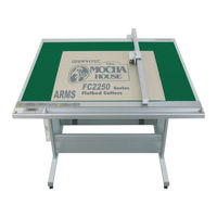
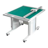
CUTTING PRO FC2250-60VC
GRAPHTEC CUTTING PRO FC2250-60VC Manuals
Manuals and User Guides for GRAPHTEC CUTTING PRO FC2250-60VC. We have
2
GRAPHTEC CUTTING PRO FC2250-60VC manuals available for free PDF download: Service Manual, User Manual
GRAPHTEC CUTTING PRO FC2250-60VC Service Manual (210 pages)
Brand:
GRAPHTEC
| Category:
Plotter
| Size: 6.92 MB
Table of Contents
Table of Contents
4
1 Introduction
9
Model Names And Basic Specifications
9
Standard Accessories
9
Main Specifications
10
External Dimensions
11
Stand Assembly Procedure
14
Mounting Procedure
15
Removing The Y Bar Retaining Brackets
16
Selecting The Vacuum Pump
17
Installation Location
18
2 Description Of Parts
19
Plotter Nomenclature
19
Control Panel
20
Types Of Cutter Blades And Their Features
22
Cutter Pen Nomenclature
23
3 Basic Operation
25
Replacing The Cutter Blade
25
Adjusting The Blade Length
28
Mounting The Cutter Pen
29
Adjusting The Pen Carriage Height
30
Turning On The Plotter And Initialization
31
Loading The Medium
32
Pause Menu Configuration
33
Setting The Cutting Conditions
34
Printing A Conditions List
36
Printing A Character Dump List
38
Printing The Self-Test Pattern
40
4 Daily Maintenance And Storage
43
5 Recommended Parts List
45
6 List Of Tools
47
Tools
47
7 Disassembly And Adjustment
49
Outer Part
49
Right Front Cover
49
Left
49
Right Rear Cover
50
Left Rear Cover
50
Pen Block Cover
51
Front Y Bar Cover
51
Y Motor Cover
52
Motor Cover
53
Motor Relay Board Cover
53
Control Box Cover
54
High Voltage Power Supply Board Cover (For Es Model Only)
54
X-Axis Drive Part
55
Motor
55
Motor Belt
56
Drive Belt
58
Front X Belt
61
Rear X Belt
62
Adjusting The X Drive Belt Tension
64
Adjusting The Front X Belt Tension
65
Adjusting The Rear X Belt Tension
67
Checking The Belt Tension Of The Front And Rear X Belt
69
Home Sensor
70
Flexible Cable
71
Pen Block Part
73
Pen Block
73
Registration Mark Sensor
77
Adjusting The Pen Arm Slider Shaft
79
Y Drive Part
80
Y Motor
80
Y Motor Belt
82
Adjusting The Y Motor Belt Tension
83
Adjusting The Y Drive Belt Tension
83
Y Bar Part
84
Y Bar
84
Preparations Before Detaching The Y Bar
86
Checking The Sliding Of The Y Bar Frame (Manual Check)
87
Adjusting The Perpendicularity Precision
88
Y Belt
90
Adjusting The Y Belt Tension
91
Y Flexible Cable
93
Preparing The Y Flexible Cable Assembly
100
Y Home Sensor
102
Y Drive Belt
104
Y Slider
106
Adjusting The Roller Pressure Of The Y Slider
110
Slider
111
Front X Slider
111
Adjusting The Roller Tension Of The Front X Slider
112
Rear X Slider
113
Adjusting The Roller Tension Of The Rear X Slider
114
Control Box
116
Main Board
116
Main Relay Board
117
Power Supply Board
118
Power Supply Relay Board
119
Replacing The Electrostatic Adhesion Plate
120
Peeling Off The Electrostatic Adhesion Plate
120
Preliminary Preparations For Pasting On New Plate
121
Attaching The Electrostatic Adhesion Plate
122
8 Electrical Adjustments
127
List Of Items Requiring Readjustment
127
Flowchart Of The Adjustment Sequence
128
The Main Board Was Replaced
128
The Pen Block Was Replaced
129
The X Home Sensor Was Replaced
129
The Y Home Sensor Was Replaced
130
The Registration Mark Sensor Was Replaced
130
The X Or Y Motor Was Replaced
130
The X Or Y Belt Was Replaced
131
The Y Bar Was Removed
131
Location Of The Boards
132
Explanation Of The Values Of The Main Board
133
Setting The Dip Switches
134
Updating The System Firmware
136
Clearing The Non-Volatile Ram
138
Inputting The Gain Value
139
Adjusting The Home Position
140
Adjusting The Pen Height
141
Adjusting The Pen Force
142
Adjusting The Distance And The Perpendicularity Accuracy
145
Adjusting The Pen Interval
148
Adjusting The Registration Mark Sensor Sensitivity
150
Adjusting The Offset Of The Registration Mark Sensor
151
Selecting The Model
153
Testing The Control Panel Keys And Home Sensors
154
About Start Up Mode
156
9 Troubleshooting
157
Troubleshooting Flowcharts
157
Checking For Faulty Rotation Of The Blade
157
The Cutting Media Cannot Be Satisfactorily Cut
158
Initialization Is Abnormal
164
Pen Up/Down Operations Are Abnormal
165
The X-Axis Backlash Is Excessive
167
The Y-Axis Backlash Is Excessive
168
The Y Or X Position Is Shifted
168
The Plotter Is Turned On But Doesn't Operate
169
Error Messages
170
Error Messages In Gp-Gl Command Mode
171
Error Messages In Hp-Gl Emulation Mode
172
The Cutting Results Are Unsatisfactory
174
10 Parts Lists
177
Mainframe
177
Stand
179
Control Panel
180
Control Unit
181
Drive Unit
182
Y Drive Section
185
Standard Accessories
188
11 Block Diagrams And Circuit Diagrams
190
Key Relay Board (Pr223281)
190
Main Relay Board (Pn6121-02B)
191
Relay Board (Pn6121-11C)
194
Flex. Board (Pn6121-03C)
195
X-Y Relay Board (Pn6121-04C)
196
Pen Flex. Board (Pn6121-05C)
197
Pen Flex. Board 1 (Pn6121-06C)
197
2-Pen Board (Pn6121-08C)
198
High Voltage Board (Pr31001C)
199
Main Board (Pn6121-01C)
200
Power Relay Board (Pn5042-04)
209
Miscellaneous
210
Advertisement
GRAPHTEC CUTTING PRO FC2250-60VC User Manual (129 pages)
Brand:
GRAPHTEC
| Category:
Plotter
| Size: 2.08 MB
Table of Contents
Preface
6
Precautions on the Handling of Cutter Pens
6
Precautions after Turning on the Plotter
7
Daily Maintenance and Storage
8
Selecting a Power Cable
9
Table of Contents
10
Model Names and Basic Specifications
14
Standard Accessories
14
Features
15
Plotter Nomenclature
16
Control Panel
17
Types of Cutter Blades and Their Features
20
Cutter Pen Nomenclature
21
Replacing the Cutter Blade
22
Adjusting the Blade Length
25
Obtaining the Correct Blade Length
25
Pen Types and Their Features
26
Basic Operational Flow
29
Connecting to Your Computer
30
Mounting the Tools
31
Adjusting the Pen Carriage Height
32
Tilting the Writing Panel
33
Turning on the Plotter and Initialization
34
Loading the Medium
35
Setting the Cutting Conditions (Setting Conditions)
36
Setting the Cutting Force (Pen Force, Creaser Force) [FORCE]
37
Setting the Speed [SPEED]
37
Setting the Cutter Blade Type and Offset [OFFSET]
38
Creaser Settings
39
Setting the Quality [QUALITY]
41
Thick Mode Settings
41
Perforation Settings
42
Running a Cutting Test
43
Cutter Pen Test
43
Creasing Tool Test
43
Cutting a Sample
44
Blade Length Adjustment
45
Media and Cutting Conditions
46
Setting the Cutting Origin
47
Using the Copy Function
48
Using the Hold Function
50
Outline of the Registration Mark Function
52
Setting the Registration Mark Mode
53
Setting the Registration Mark Pattern
55
Setting the Registration Mark Spacing
56
Setting the Center Registration Mark
56
Registration Mark Distance Adjustment
57
USER (Manual Input)
57
Custom
58
Setting the Registration Mark Size
59
Setting the Registration Mark Offset
60
Adjusting the Registration Mark Sensor
61
Adjusting the Registration Mark Sensor by Using a Pre-Printed Cross Symbol and a Plotted Cross Symbol
61
Adjusting the Registration Mark Sensor by Using One Plotted and One Cut Cross Symbol
62
Setting the Registration Mark Detection Judgment Level
64
Adjusting the Sensitivity of the Registration Mark Sensor
65
Setting the Registration Mark Detection Speed
67
Setting the Sensing Interval
68
Axis Adjustment
69
Registration Mark Detection
71
Manual Detection
72
Setting the Registration Mark Cutting Function
74
Setting the Registration Mark Detection Start Position
75
PAUSE Menu Configuration
77
Clearing the Buffer
78
Raising/Lowering the Tool
79
Moving the Pen Carriage to the Upper Right Position
80
Setting the Communication Conditions
81
Setting the Data Format to be Received
82
Assigning THICK Mode
83
Setting the Overlay Function
84
Assigning Tool Numbers
85
Assigning Perforation Cutting
86
Setting the Tool Interval Adjustment Value
87
Setting the Distance Adjustment Values
88
Sorting
89
Rotating the Coordinate Axes
90
Setting the Cutting/Plotting Area
91
Setting the Mirror Mode
93
Scaling the Image Data
94
Setting the Initial Cutting Force
95
Setting the Offset Force
96
Setting the Offset Angle
97
Setting the Step Pass
98
Setting the Tool Movement Speed
99
Setting the Pen Carriage Movement Speed
100
Setting the Step Movement Distance
100
Setting the Low Movement Speed
101
Setting the High Movement Speed
102
Printing a Conditions List
103
Printing the Self-Test Pattern
105
Printing a Character Dump List
106
Special Functions
107
Troubleshooting
110
Error Messages
113
Selecting the Vacuum Pump
117
Installation Location
118
Vacuum Pump Wiring
119
Main Specifications
121
External Dimensions
122
Index
125
Advertisement
Related Products
GRAPHTEC FC2250 Series
GRAPHTEC CUTTING PRO FC2250-120MG
GRAPHTEC CUTTING PRO FC2250-120ES
GRAPHTEC CUTTING PRO FC2250-120VC
GRAPHTEC CUTTING PRO FC2250-180ES
GRAPHTEC CUTTING PRO FC2250-180VC
GRAPHTEC Cutting PRO FC2232-60VC
GRAPHTEC Cutting PRO FC2231-90ES
GRAPHTEC Cutting PRO FC2232-90VCT
GRAPHTEC Cutting PRO FC2231-EXMG
GRAPHTEC Categories
Plotter
Data Loggers
Scanner
Cutter
Printer
More GRAPHTEC Manuals
Login
Sign In
OR
Sign in with Facebook
Sign in with Google
Upload manual
Upload from disk
Upload from URL