Table of Contents
Advertisement
Quick Links
Advertisement
Table of Contents

Related Manuals for GRAPHTEC CUTTING PRO FC2250 Series


Summary of Contents for GRAPHTEC CUTTING PRO FC2250 Series
- Page 1 FC2250 SERIES CUTTING PRO USER’S MANUAL MANUAL NO.FC2250-UM-151 www.delinit.by...
- Page 2 TO ENSURE SAFE AND CORRECT USE TO ENSURE SAFE AND CORRECT USE • To ensure safe and correct use of your plotter, read this Manual thoroughly before use. • After having read this Manual, keep it in a handy location for quick reference as needed. •...
- Page 3 If the plotter requires repair, contact your sales representative • or nearest Graphtec vendor. After confirming that smoke is no longer being generated, contact your sales representative or nearest Graphtec vendor to request repair. • Never try to perform repair yourself.
- Page 4 Safety Precautions Safety Precautions Do not allow dust or metallic matter to adhere to the Do not use the power cord if it is damaged. power plug. • Use of a damaged cord may result in electrical shock or a fire •...
- Page 5 • Use of the plotter in such status may result in electrical shock or a fire hazard due to current leakage. • Contact your sales representative or nearest Graphtec vendor to request repair. Prohibited Unplug the power When using the cutter pen, take care not to extend cord from the socket the cutter blade excessively.
-
Page 6: Preface
PREFACE Precautions on the Handling of Cutter Pens This product uses a cutting blade. To prevent injuries (when replacing the cutter blade, installing the cutter pen, etc.), take the following precautions when handling the cutter blade. Cutter Blade The blades are sharp. Be careful not to cut your fingers or prick yourself when handling the cutter pen. Blade tip Return used blades to the accessory cutter blade case and throw them all out together when the whole case has been filled. -
Page 7: Precautions After Turning On The Plotter
PREFACE Precautions After Turning on the Plotter During operations, immediately after completion of operations, and when setting cutting plotter functions, the pen carriage, Y bar, and other parts which are not fixed, may move suddenly. Do not let your hands, hair, or clothing get too close to the moving parts or within their range of movement. -
Page 8: Daily Maintenance And Storage
PREFACE Daily Maintenance and Storage During daily maintenance, pay particular attention to the following points. (1) Do not lubricate the plotter mechanisms. (2) To clean the plotter's metal parts, either wipe the soiled areas with a dry cloth or with a cloth that has been dampened with a neutral detergent diluted with water. -
Page 9: Selecting A Power Cable
PREFACE Selecting a Power Cable Be sure to refer to the following tables if you wish to use a cable other than the one supplied as an accessory. Table 1. 100 V to 120 V Power Supply Voltage Range Supply Voltage Reference Plug Configuration Plug Type... -
Page 10: Table Of Contents
CONTENTS CONTENTS PREFACE............. . I Notes on the Use of This Manual . - Page 11 CONTENTS Blade Length Adjustment ..........3-18 3.10 Media and Cutting Conditions .
- Page 12 CONTENTS 5.14 Rotating the Coordinate Axes ......... . . 5-15 5.15 Setting the Cutting/Plotting Area .
- Page 13 CHAPTER PRODUCT SUMMARY PRODUCT SUMMARY 1.1 Model Names and Basic Specifications 1.2 Standard Accessories 1.3 Features 1.4 Plotter Nomenclature 1.5 Control Panel www.delinit.by...
-
Page 14: Model Names And Basic Specifications
Chapter 1 PRODUCT SUMMARY 1.1 Model Names and Basic Specifications The FC2250 series comprises the following models. Model Media hold-down method Cutting area FC2250-60VC Vacuum suction 610 x 920 mm FC2250-120MG Magnetic FC2250-120ES Electrostatic adhesion 1200 x 920 mm FC2250-120VC Vacuum suction FC2250-180ES Electrostatic adhesion... -
Page 15: Features
Chapter 1 PRODUCT SUMMARY 1.3 Features • The FC2250 series plotters provide a sharply-defined cutting edge. • The cutting force can be freely selected in a 40-step range (max. 9.8 N[1 kgf]). The maximum cutting speed is 400 mm/s. The high acceleration rate increases the overall cutting speed. •... -
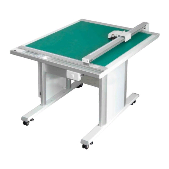
Page 16: Plotter Nomenclature
Chapter 1 PRODUCT SUMMARY 1.4 Plotter Nomenclature The names of the plotter parts are as follows. Pen carriage Y bar Control panel Writing panel CHART HOLD key (ES models only) Tilt lever Interface connector Main Stand Power inlet Power switch USB interface RS-232C interface RS-232C... -
Page 17: Control Panel
Chapter 1 PRODUCT SUMMARY 1.5 Control Panel POWER Lamp PROMPT Lamp F1 to F4 Key POSITION Key COPY Key CONDITIOS Key NEXT Key PAUSE Key ENTER Key TEST Key ORIGIN Key Indicator Lamps ....The POWER lamp remains lit (green) while the plotter is on....The PROMPT lamp lights (red) when the plotter receives data that will cause the pen carriage to move outside the effective cutting area or receives the Prompt Light command (T) from the computer. - Page 18 Chapter 1 PRODUCT SUMMARY ......After setting a function or condition at the control panel, press the [ENTER] key to register your setting. To reset the plotter, concurrently press the [ENTER] and [ORIGIN] keys. (Key reset function) ......Runs a cutting test to check whether the currently selected cutting conditions are compatible with the medium loaded.
- Page 19 CHAPTER CUTTER BLADES, CUTTER PENS AND PENS PRODUCT SUMMARY 2.1 Types of Cutter Blades and Their Features 2.2 Cutter Pen Nomenclature 2.3 Replacing the Cutter Blade 2.4 Adjusting the Blade Length 2.5 Pen Types and Their Features www.delinit.by...
-
Page 20: Types Of Cutter Blades And Their Features
Chapter 2 CUTTER BLADES, CUTTER PENS AND PENS 2.1 Types of Cutter Blades and Their Features Handle cutter blades with care! Blade type Blade features Supersteel blades CB15U (φ1.5) • Less expensive than other types of blades. • The maximum cutting distance is about 4000 m (depending on the medium and cutting pressure used). -
Page 21: Cutter Pen Nomenclature
Chapter 2 CUTTER BLADES, CUTTER PENS AND PENS 2.2 Cutter Pen Nomenclature Handle cutter blades with care! PHP31-CB09-HS Cutter pen for 0.9-mm diameter blades Protective cap Plunger Holder A Spring Cutter blade* Holder B Plunger cap Blade length adjustment knob (blue) * The CB09UA supersteel blade is shown in the figure above. -
Page 22: Replacing The Cutter Blade
Chapter 2 CUTTER BLADES, CUTTER PENS AND PENS 2.3 Replacing the Cutter Blade There are four types of cutter pen. Each type has different diameter blades. The blade diameter is indicated by the color of the blade length adjustment knob as shown in the table below. When replacing the cutter blade, check the table below to ensure that you are using the correct combination of cutter pen and cutter blade. - Page 23 Chapter 2 CUTTER BLADES, CUTTER PENS AND PENS Color of the blade length adjustment knob: Red PHP31-CB15-HS cutter pen for 1.5 mm blades (1) Remove holder (B) by turning the blade length adjustment knob in the counterclockwise direction. Holder (B) (2) Remove the cutter blade from the holder.
- Page 24 Chapter 2 CUTTER BLADES, CUTTER PENS AND PENS Color of the blade length adjustment knob: Silver PHP34-CB30-HS cutter pen for3.0 mm diameter blades fitted with a spring (1) Turn the blade length adjustment knob to retract the cutter blade inside the plunger. (2) Remove the plunger by turning the plunger cap in the counterclockwise direction.
-
Page 25: Adjusting The Blade Length
Chapter 2 CUTTER BLADES, CUTTER PENS AND PENS 2.4 Adjusting the Blade Length Be sure to correctly adjust the blade length. If the blade length is too long for the thickness of the medium being used, you may damage the writing panel and/or the cutter blade. Adjusting the Blade Length (1) The blade length is adjusted by turning the blade adjustment knob (blue, red, green or silver). -
Page 26: Pen Types And Their Features
Chapter 2 CUTTER BLADES, CUTTER PENS AND PENS 2.5 Pen Types and Their Features Pen types Pen features • Water based fiber-tip pens (KF550 Series) 8 colors are available • Line width ranges from 0.3 to 0.7 mm • Easier to handle than other pen types •... - Page 27 Chapter 2 CUTTER BLADES, CUTTER PENS AND PENS Tool types Tool features Creasing tools (CP-002/003) CP-002 • Roller-type creasing tool • Used for creasing card up to a thickness of around 0.5 mm CP-003 • Roller-type creasing tool • Used for creasing E/F/G-flute grade cardboard Note: Creasing may be difficult to perform on some types of media.
- Page 28 CHAPTER PREPARATIONS FOR CUTTING/PLOTTING PRODUCT SUMMARY 3.1 Basic Operational Flow 3.2 Connecting to a Computer 3.3 Mounting the Tools 3.4 Adjusting the Pen Carriage Height 3.5 Tilting the Writing Panel 3.6 Turning on the Plotter and Initialization 3.7 Loading the Medium 3.8 Setting the Cutting Conditions (Setting Conditions) 3.9 Running a Cutting Test...
-
Page 29: Basic Operational Flow
Chapter 3 PREPARATIONS FOR CUTTING/PLOTTING 3.1 Basic Operational Flow For smooth operation, please follow the steps outlined below and make the appropriate settings explained in the relevant sections. (1) Before turning on the power supply, make sure that the plotter is connected to your computer and to any other peripheral devices as required. -
Page 30: Connecting To Your Computer
Use a USB cable or an RS-232C cable in accordance with the interface chosen. Obtain a Graphtec- approved interface cable that is compatible with your computer. -
Page 31: Mounting The Tools
Chapter 3 PREPARATIONS FOR CUTTING/PLOTTING 3.3 Mounting the Tools When you are facing the pen carriage, the holder at the left is tool holder 1 and the holder at the right tool holder 2. Tool holder 2 Tool holder 1 Registration mark sensor Example showing tools mounted Always mount the cutter pen in tool holder 2. -
Page 32: Adjusting The Pen Carriage Height
Chapter 3 PREPARATIONS FOR CUTTING/PLOTTING 3.4 Adjusting the Pen Carriage Height Adjust the height of the pen carriage to suit the thickness of the medium. • Always make sure that the writing panel is in the horizontal position before making this adjustment. •... -
Page 33: Tilting The Writing Panel
Chapter 3 PREPARATIONS FOR CUTTING/PLOTTING 3.5 Tilting the Writing Panel This plotter can be used with the writing panel tilted up to 60°. The tilt can be adjusted in the following way. When using an MG (magnetic hold-down) or ES (electrostatic adhesion) model in a tilted position, please observe the following points. -
Page 34: Turning On The Plotter And Initialization
Chapter 3 PREPARATIONS FOR CUTTING/PLOTTING 3.6 Turning on the Plotter and Initialization The moment you turn on the power, the plotter's Y bar and pen carriage will start to move. Do not put your hands or other objects on the writing panel. Such actions are dangerous. (1) Make sure the power is turned off. -
Page 35: Loading The Medium
Chapter 3 PREPARATIONS FOR CUTTING/PLOTTING 3.7 Loading the Medium • This plotter is available with a magnetic writing panel, a vacuum suction writing panel, or an electrostatic writing panel. Note that the medium is loaded differently depending on the media hold-down method. •... -
Page 36: Setting The Cutting Conditions (Setting Conditions)
Chapter 3 PREPARATIONS FOR CUTTING/PLOTTING 3.8 Setting the Cutting Conditions (Setting Conditions) This plotter lets you register eight different groups of cutting conditions in the plotter's memory. The cutting conditions stored in memory are referred to as setting conditions. Specify each group of setting conditions to match a particular media type. -
Page 37: Setting The Cutting Force (Pen Force, Creaser Force) [Force]
Chapter 3 PREPARATIONS FOR CUTTING/PLOTTING (3) Press a key from [F1] to [F4] to move the blinking cursor to the parameter that you wish to set. (4) Change the setting value of the parameter that you wish to set. (5) Press the [ENTER] key to register the setting conditions in the plotter’s internal memory. To cancel your settings, press the [NEXT] key. -
Page 38: Setting The Cutter Blade Type And Offset [Offset]
Chapter 3 PREPARATIONS FOR CUTTING/PLOTTING (2) Press the [CONDITIONS] key to display the following screen. (The display will differ according to the setting conditions that have been made.) FORCE OFFSET X20 COND1 09U 0 30 CHANGE TOOL1 SPEED QUALITY (3) Press the [F2] key to move the blinking cursor to the SPEED parameter. FORCE OFFSET X20 COND1... -
Page 39: Creaser Settings
Chapter 3 PREPARATIONS FOR CUTTING/PLOTTING (6) When the displayed settings are correct, press the [ENTER] key. To cancel your settings, press the [NEXT] key. Creaser Settings The creaser settings enable you to specify the creasing mode, the spacing between creases, the number of creasing operations and the creasing start and end points. - Page 40 Chapter 3 PREPARATIONS FOR CUTTING/PLOTTING (5) Use the [ ] or [ ] key to move the position of the blinking cursor, and the [ ] or [ ] key to select the value. Setting range: 0 to 9.99 mm Mode 2 (Crease two lines) Mode 3 (Crease three lines) Spacing...
-
Page 41: Setting The Quality [Quality]
Chapter 3 PREPARATIONS FOR CUTTING/PLOTTING Setting the Quality [QUALITY] This setting determines the quality of the cut or plotted results. Please see Section 3.10, "Media and Cutting Conditions" for further details on the setting values. (1) With the plotter in Ready status, press a key from [F1] to [F4] to select the COND No. that you wish to change. (2) Press the [CONDITIONS] key to display the following screen. -
Page 42: Perforation Settings
Chapter 3 PREPARATIONS FOR CUTTING/PLOTTING • • (4) The active mode is indicated by the [ ] mark. Press the [F1] and [F3] key to move the [ ] mark between Mode 1 and Mode 2 and select the desired mode. Mode 1: Perform overcutting for the cutting start and end points and for corners with acute angles to prevent uncut areas. -
Page 43: Running A Cutting Test
Chapter 3 PREPARATIONS FOR CUTTING/PLOTTING 3.9 Running a Cutting Test A cutting test is performed to check whether the specified cutting conditions are suitable for the tool and media being used. Perform the test that is appropriate for the tool that you are using. The pen carriage starts moving as soon as a cutting test is selected. -
Page 44: Cutting A Sample
Chapter 3 PREPARATIONS FOR CUTTING/PLOTTING (3) With the plotter in Ready status, press a key from [F1] to [F4] to select the COND No. for the creasing tool test. Select either "CP001" or "CP002" as the cutter blade type. (4) Use the [ ] keys to move the pen carriage (the tip of the tool selected by the current setting)to the starting position for the cutting test. -
Page 45: Blade Length Adjustment
Chapter 3 PREPARATIONS FOR CUTTING/PLOTTING (7) Press the [F2] key (BALL) for GP-GL, and the [F4] key (BOX) for HP-GL. When GP-GL has been selected When HP-GL has been selected FORCE OFFSET FORCE OFFSET BOX _ A BALL S BOX _ B BALL L SPEED QUALITY... -
Page 46: Media And Cutting Conditions
Chapter 3 PREPARATIONS FOR CUTTING/PLOTTING 3.10 Media and Cutting Conditions Blade length Adjust the blade length according to the thickness of the medium. Please see Section 2.4, "Adjusting the Blade Length" and Section 3.9, "Running a Cutting Test" for the setting procedure. FORCE, SPEED, QUALITY Use the following table as a guideline to set these conditions. -
Page 47: Setting The Cutting Origin
Chapter 3 PREPARATIONS FOR CUTTING/PLOTTING 3.11 Setting the Cutting Origin This function allows you to move the starting point of cutting to the desired position as shown in the figure below. Newly selected origin Cutting from the new origin Cutting from the original origin Original origin (1) Use the [ ] keys to move the pen carriage (the tip of the tool selected by the current setting) to the... -
Page 48: Using The Copy Function
Chapter 3 PREPARATIONS FOR CUTTING/PLOTTING 3.12 Using the Copy Function This function allows you to automatically cut duplicates of the data sent from the computer. Once the data has been stored in the plotter's receive buffer, it can be repeatedly cut. (1) Send data to the plotter and then perform a cutting operation to enable the data to be stored in the plotter's buffer. - Page 49 Chapter 3 PREPARATIONS FOR CUTTING/PLOTTING The following figures illustrate the sequence in which copies are cut, with the shaded areas representing the parts of the medium that are not cut. Copies are normally cut in the sequence shown below. COPY space 3rd copy 6th copy COPY space...
-
Page 50: Using The Hold Function
Chapter 3 PREPARATIONS FOR CUTTING/PLOTTING 3.13 Using the Hold Function Press the [PAUSE] key during a cutting or plotting operation to temporarily suspend the cutting or plotting operation. When the PAUSE key setting in Special Functions is "Pause" When the plotter is paused, an operation selection menu appears. Select whether to continue or quit the suspended cutting or plotting operation. - Page 51 CHAPTER REGISTRATION MARK SETTINGS AND DETECTION PRODUCT SUMMARY 4.1 Outline of the Registration Mark Function 4.2 Setting the Registration Mark Mode 4.3 Setting the Registration Mark Pattern 4.4 Setting the Registration Mark Adjustment Distance 4.5 Setting the Registration Mark Size 4.6 Setting the Registration Mark Offset 4.7 Adjusting the Registration Mark Sensor 4.8 Setting the Registration Mark Detection Judgment Level...
-
Page 52: Outline Of The Registration Mark Function
Chapter 4 REGISTRATION MARK SETTINGS AND DETECTION 4.1 Outline of the Registration Mark Function The registration mark function allows you to align the orientation of the plotter’s X and Y axes with the coordinate axes on a medium that is pre-printed with registration marks or other marks. The plotter uses a sensor to read the registration marks printed on the media, and then adjusts the axes to match the coordinate data so that cutting can be performed on pre-printed media without any shift between the print and cut data. -
Page 53: Setting The Registration Mark Mode
Chapter 4 REGISTRATION MARK SETTINGS AND DETECTION 4.2 Setting the Registration Mark Mode This mode is used to specify the angle and distance adjustment methods, as well as to specify the distance between registration marks for skipping by the sensor during registration mark detection. 2-point reading: The plotter performs adjustment between points 1-2 and of a single axis (angle adjustment). - Page 54 Chapter 4 REGISTRATION MARK SETTINGS AND DETECTION To perform manual axis adjustment using a pre-printed frame or other marks on the medium as reference points, press the [F2] key (AXIS). To perform automatic or manual detection of the registration marks, press the [F4] key (MARKS). When the displayed setting is satisfactory, press the [ENTER] key to confirm your selection.
-
Page 55: Setting The Registration Mark Pattern
Chapter 4 REGISTRATION MARK SETTINGS AND DETECTION 4.3 Setting the Registration Mark Pattern Your plotter can read five registration mark patterns: 1, 2, 3, Mirror 1 and Mirror 2. If pattern 3, Mirror 1 or Mirror 2 has been selected, this function allows you to set the spacing between the registration mark line segments. -
Page 56: Setting The Registration Mark Spacing
Chapter 4 REGISTRATION MARK SETTINGS AND DETECTION Setting the Registration Mark Spacing (1) If registration mark 3, mirror 1 or mirror has been selected, the menu for setting the registration mark pattern spacing is displayed. FORCE OFFSET MARK TYPE:3 SPACING = 3.0 mm SPEED QUALITY... -
Page 57: Registration Mark Distance Adjustment
Chapter 4 REGISTRATION MARK SETTINGS AND DETECTION 4.4 Registration Mark Distance Adjustment The distance between registration marks can be adjusted automatically. If 5 mm was selected for CUSTOM, for example, and the distance between registration marks was read as 312 mm, any distance less than 5 mm is rounded off to the nearest whole number. -
Page 58: Custom
Chapter 4 REGISTRATION MARK SETTINGS AND DETECTION (3) If the registration mark mode setting was 3-point reading or 4-point reading, the menu for adjusting the distance between points 1 and 3 will be displayed. Make the settings in the same way as for the distance between points 1 and 2. -
Page 59: Setting The Registration Mark Size
Chapter 4 REGISTRATION MARK SETTINGS AND DETECTION 4.5 Setting the Registration Mark Size This function allows you to specify the size of the registration marks drawn on the medium. (1) Press the [PAUSE] key to select PAUSE mode. (2) Press the [NEXT] key repeatedly until the following menu is displayed. FORCE OFFSET MARK... -
Page 60: Setting The Registration Mark Offset
Chapter 4 REGISTRATION MARK SETTINGS AND DETECTION 4.6 Setting the Registration Mark Offset The default position of the origin point is the lower left corner of the cutting/plotting area. Use this function whenever you wish to move the registration mark origin point. (1) Press the [PAUSE] key to select PAUSE mode. -
Page 61: Adjusting The Registration Mark Sensor
Chapter 4 REGISTRATION MARK SETTINGS AND DETECTION 4.7 Adjusting the Registration Mark Sensor This function allows you to adjust the registration mark sensor. Two adjustment methods are provided—use the one that best suits your requirements. Adjusting the Registration Mark Sensor by Using a Pre-printed Cross Symbol and a Plotted Cross Symbol This function allows you to adjust the registration mark sensor by reading a pre-printed cross symbol, and then plotting another cross symbol for use in adjustment. -
Page 62: Adjusting The Registration Mark Sensor By Using One Plotted And One Cut Cross Symbol
Chapter 4 REGISTRATION MARK SETTINGS AND DETECTION (10) Use the [ ] keys to move the pen carriage (the tip of the tool selected by the current setting) to the area under the cross symbol indicated in the diagram below) and then press the [ENTER] key. The sensor will read the cross symbol. - Page 63 Chapter 4 REGISTRATION MARK SETTINGS AND DETECTION (6) Press the [F3] key (ADJ. SENS) to display the menu shown below. FORCE OFFSET ADJUST SENS. SPEED QUALITY (7) Press the [F2] key (X+) to adjust the X-axis sensor, and the [F4] key (Y+) to adjust the Y-axis sensor. The prompt shown below is displayed.
-
Page 64: Setting The Registration Mark Detection Judgment Level
Chapter 4 REGISTRATION MARK SETTINGS AND DETECTION 4.8 Setting the Registration Mark Detection Judgment Level This function sets the color density judgment level of the line segments that are read during a registration mark detection operation. This level determines the existence of a line segment by a change in density of the specified percentage from an area where there are no line segments (white area). -
Page 65: Adjusting The Sensitivity Of The Registration Mark Sensor
Chapter 4 REGISTRATION MARK SETTINGS AND DETECTION registration marks can be detected) but the floating up of the medium from the surface of the plotter or dirt on the medium may cause erroneous detection. Make settings for registration mark pattern 3, Mirror 1 and Mirror 2 in the same way. Adjusting the Sensitivity of the Registration Mark Sensor If you have changed the medium to a different type, we recommend that you perform this procedure. - Page 66 Chapter 4 REGISTRATION MARK SETTINGS AND DETECTION (10) Use the [ ] keys to move the pen carriage (the tip of the tool selected by the current setting) to a blank area of the medium (an area where there is no drawing) and then press the [ENTER] key. The prompt shown at the left is displayed during the adjustment process, and the prompt shown at the right is displayed when adjustment has been completed.
-
Page 67: Setting The Registration Mark Detection Speed
Chapter 4 REGISTRATION MARK SETTINGS AND DETECTION 4.9 Setting the Registration Mark Detection Speed This function sets the speed of the pen carriage at the time when registration mark lines are detected. Change the speed setting if registration marks cannot be detected due to the type of media used or the thickness of the registration mark lines. -
Page 68: Setting The Sensing Interval
Chapter 4 REGISTRATION MARK SETTINGS AND DETECTION 4.10 Setting the Sensing Interval If the line segments are fine, registration marks may not be detected even when the slowest registration mark detection speed has been set. If the interval has been set to 0, the registration marks are detected through sampling during movement. -
Page 69: Axis Adjustment
Chapter 4 REGISTRATION MARK SETTINGS AND DETECTION 4.11 Axis Adjustment When AXIS has been selected for the registration mark mode, axis adjustment is performed manually. If 2, 3, or 4 points are specified on the X and Y axes, adjustment is performed for the angle of the coordinate axes (X-axis and Y-axis tilt) and the distance (line segment length). - Page 70 Chapter 4 REGISTRATION MARK SETTINGS AND DETECTION If the value you input is exceedingly large (1.5 times or greater) or very small (0.5 times or less), or if the angle of tilt with respect to the original axis tilt is 45° or greater, the following prompt is displayed. In this case, please re-input the value.
-
Page 71: Registration Mark Detection
Chapter 4 REGISTRATION MARK SETTINGS AND DETECTION 4.12 Registration Mark Detection When MARKS has been selected for the registration mark mode, the plotter detects the registration marks printed on the medium and adjusts the angle of the coordinate axes (X-axis and Y-axis tilt) and the distance (line segment length). -
Page 72: Manual Detection
Chapter 4 REGISTRATION MARK SETTINGS AND DETECTION (4) Press the [F1], [F2] or [F3] key to select the corresponding number for the Mark Move No. setting. The following prompt is displayed while the plotter detects the adjustment points. FORCE OFFSET ARMS IS OPERATING WAIT.. - Page 73 Chapter 4 REGISTRATION MARK SETTINGS AND DETECTION (4) Use the [ ] keys to move the pen carriage (the tip of the tool selected by the current setting) to the first point position ( point 1 area) and then press the [ENTER] key. The plotter detects point 1. Registration mark pattern 1 Registration mark pattern 2 Registration mark pattern 3...
-
Page 74: Setting The Registration Mark Cutting Function
Chapter 4 REGISTRATION MARK SETTINGS AND DETECTION 4.13 Setting the Registration Mark Cutting Function If your registration mark pattern is Mirror 1 or Mirror 2, the registration marks can be cut after they have been detected. (1) Select either AXIS or MARKS for the registration mark mode (see Section 4.2, "Setting the Registration Mark Mode".) (2) With the plotter in Ready status, press the [ORIGIN] key to display the following menu. -
Page 75: Setting The Registration Mark Detection Start Position
Chapter 4 REGISTRATION MARK SETTINGS AND DETECTION 4.14 Setting the Registration Mark Detection Start Position This function sets the start position for registration mark detection. (1) Select either AXIS or MARKS for the registration mark mode (see Section 4.2, "Setting the Registration Mark Mode". (2) With the plotter in Ready status, press the [ORIGIN] key to display the following menu. - Page 76 CHAPTER FUNCTION SETTINGS AND OPERATIONS PRODUCT SUMMARY 5.1 PAUSE Menu Configuration 5.2 Clearing the Buffer 5.3 Raising/Lowering the Tool 5.4 Moving the Pen Carriage to the Upper Right Position 5.5 Setting the Communication Conditions 5.6 Setting the Data Format to be Received 5.7 Assigning THICK Mode 5.8 Setting the Overlay Function 5.9 Assigning Tool Numbers...
-
Page 77: Pause Menu Configuration
Chapter 5 FUNCTION SETTINGS AND OPERATIONS 5.1 PAUSE Menu Configuration When the plotter is in PAUSE mode, each of the functions listed below can be accessed by pressing the [NEXT] key until the desired menu appears and then pressing function key [F1] [F2] [F3] or [F4] to select the desired menu parameter. -
Page 78: Clearing The Buffer
Chapter 5 FUNCTION SETTINGS AND OPERATIONS 5.2 Clearing the Buffer This function allows you to clear all the output data in the plotter's buffer. (1) Press the [PAUSE] key to select PAUSE mode. (2) Press the [NEXT] key repeatedly until the following menu is displayed. FORCE OFFSET MARK... -
Page 79: Raising/Lowering The Tool
Chapter 5 FUNCTION SETTINGS AND OPERATIONS 5.3 Raising/Lowering the Tool This function allows you to raise or lower the tool from the control panel. (1) Press the [PAUSE] key to select PAUSE mode. (2) Press the [NEXT] key repeatedly until the following menu is displayed. FORCE OFFSET MARK... -
Page 80: Moving The Pen Carriage To The Upper Right Position
Chapter 5 FUNCTION SETTINGS AND OPERATIONS 5.4 Moving the Pen Carriage to the Upper Right Position This function allows you to move the pen carriage to the upper right (VIEW) position. (1) Press the [PAUSE] key to select PAUSE mode. (2) Press the [NEXT] key repeatedly until the following menu is displayed. -
Page 81: Setting The Communication Conditions
Chapter 5 FUNCTION SETTINGS AND OPERATIONS 5.5 Setting the Communication Conditions When your plotter is connected via an RS-232C cable to a computer, be sure to set identical communication conditions in the software and OS communication settings for the data transfer rate (baud rate), data length, and parity. -
Page 82: Setting The Data Format To Be Received
Before data is sent from the computer, your plotter must be set to recognize the data format (command mode) sent by the software. Your plotter supports two data formats (command modes): GP-GL (Graphtec commands) and HP-GL commands. Select the command mode best suited for your application. -
Page 83: Assigning Thick Mode
Chapter 5 FUNCTION SETTINGS AND OPERATIONS 5.7 Assigning THICK Mode This function allows you to assign the THICK mode to COND Nos. 1 to 8. THICK mode is used for cutting thick media such as masking rubber for sandblasting, thick pattern paper for apparel design as well as for hard media such as acrylic film. -
Page 84: Setting The Overlay Function
Chapter 5 FUNCTION SETTINGS AND OPERATIONS 5.8 Setting the Overlay Function The Overlay function enables repeated cutting to be performed on a medium that cannot be cut with one cutting operation. In the first cutting operation, a cutting force that is lighter than the specified FORCE value is used to leave cutting trace marks on the medium. -
Page 85: Assigning Tool Numbers
Chapter 5 FUNCTION SETTINGS AND OPERATIONS 5.9 Assigning Tool Numbers This function enables you to assign tool holder 1 and tool holder to COND Nos. 1 to 8. If the application software is used to perform pen exchange operations, "PROGRAM" must be selected for the CONDITION PRIORITY setting (please see Section 5.27, "Using the Special Functions"). -
Page 86: Assigning Perforation Cutting
Chapter 5 FUNCTION SETTINGS AND OPERATIONS 5.10 Assigning Perforation Cutting This function allows you to assign the perforation cutting operation to COND Nos. 1 to 8. (1) Press the [PAUSE] key to select PAUSE mode. (2) Press the [NEXT] key repeatedly until the following menu is displayed. FORCE OFFSET FUNCTION... -
Page 87: Setting The Tool Interval Adjustment Value
Chapter 5 FUNCTION SETTINGS AND OPERATIONS 5.11 Setting the Tool Interval Adjustment Value This function allows you to make adjustments for any deviation between the initial drawing/cutting positions of tool holder 1 and tool holder 2. Use plotting pens to draw the lines for this adjustment and specify the same plotting conditions for tool holder 1 and tool holder 2. -
Page 88: Setting The Distance Adjustment Values
Chapter 5 FUNCTION SETTINGS AND OPERATIONS 5.12 Setting the Distance Adjustment Values This function is used to correct any discrepancies in the lengths of the cut or plotted line segments. If, for example, the DISTANCE ADJUST setting is specified as 0.05%, and the distance of the cut is 500 mm, the cut distance is increased by 500 x 0.05% (= 0.25 mm), which means that the total cut distance is 500.25 mm. -
Page 89: Sorting
Chapter 5 FUNCTION SETTINGS AND OPERATIONS 5.13 Sorting Sorting helps prevent wasted time in tool changes and reduces the time required for a cutting/plotting operation. When sorted data from the software is received, less time is required for processing than when sorting is performed on your plotter. -
Page 90: Rotating The Coordinate Axes
Chapter 5 FUNCTION SETTINGS AND OPERATIONS 5.14 Rotating the Coordinate Axes This function is used to move the origin and rotate the coordinate axes by 90° as shown in the figure below. Origin in ROTATE mode Coordinates when ROTATE mode is selected (ON) Coordinates when Origin ROTATE mode is not selected (OFF) -
Page 91: Setting The Cutting/Plotting Area
Chapter 5 FUNCTION SETTINGS AND OPERATIONS 5.15 Setting the Cutting/Plotting Area The U.R. (Upper Right) and L.L. (Lower Left) functions are used to specify the effective cutting area of the plotter so that any data specifying coordinate positions outside of the effective cutting area is disregarded. The origin moves together with the new cutting area. - Page 92 Chapter 5 FUNCTION SETTINGS AND OPERATIONS Use the[ ] keys to move the pen carriage (the tip of the tool selected by the current setting) to the desired new U.R. point and then press the [ENTER] key. At such time, the X= and Y= coordinate values respectively represent the current pen carriage position as X- and Y-axis displacements from the original origin.
-
Page 93: Setting The Mirror Mode
Chapter 5 FUNCTION SETTINGS AND OPERATIONS 5.16 Setting the Mirror Mode When MIRROR mode is selected using this function, the origin and coordinate axes are inverted as shown in the figure below. Origin when MIRROR mode is selected MIRROR mode is selected (ON) MIRROR mode is not selected (OFF) Origin (1) Press the [PAUSE] key to select PAUSE mode. -
Page 94: Scaling The Image Data
Chapter 5 FUNCTION SETTINGS AND OPERATIONS 5.17 Scaling the Image Data This function is used to expand or reduce the image data using the program origin as the starting point. (1) Press the [PAUSE] key to select PAUSE mode. (2) Press the [NEXT] key repeatedly until the following menu is displayed. FORCE OFFSET FUNCTION... -
Page 95: Setting The Initial Cutting Force
Chapter 5 FUNCTION SETTINGS AND OPERATIONS 5.18 Setting the Initial Cutting Force This function is effective in THICK mode, the mode used mainly to cut thick media. When a thick medium is cut, more time than usual may be required for the blade to reach the base of the medium even if a suitable cutting force has been specified. -
Page 96: Setting The Offset Force
Chapter 5 FUNCTION SETTINGS AND OPERATIONS 5.19 Setting the Offset Force Since the direction in which the blade tip is facing cannot be determined during initialization of the plotter, initial blade control must be performed. The Offset Force function is used to specify the force applied during initial blade control. -
Page 97: Setting The Offset Angle
Chapter 5 FUNCTION SETTINGS AND OPERATIONS 5.20 Setting the Offset Angle Your plotter rotates the blade tip according to the initial angle of rotation required by each line segment defined in the data sent from the computer. This operation is called "initial blade control". The OFFSET ANGLE function specifies the reference blade offset angle for determining whether or not to perform initial blade control. -
Page 98: Setting The Step Pass
Chapter 5 FUNCTION SETTINGS AND OPERATIONS 5.21 Setting the Step Pass Use this function when you intend to cut extremely detailed data. The cutting data sent from the computer will be processed in blocks corresponding to the number of steps specified by the STEP PASS function, thereby ensuring consistent blade control and higher cutting quality. -
Page 99: Setting The Tool Movement Speed
Chapter 5 FUNCTION SETTINGS AND OPERATIONS 5.22 Setting the Tool Movement Speed This function allows you set the movement speed of the tool in raised status separately from the cutting/ plotting speed. A tool movement that is faster than the cutting/plotting speed enables a reduction in the overall cutting/plotting time. -
Page 100: Setting The Pen Carriage Movement Speed
Chapter 5 FUNCTION SETTINGS AND OPERATIONS 5.23 Setting the Pen Carriage Movement Speed This setting determines how far and how fast the pen carriage moves when the [ ] keys are used to move it. When one of the [ ] keys is pressed initially, the pen carriage moves only the specified distance. -
Page 101: Setting The Low Movement Speed
Chapter 5 FUNCTION SETTINGS AND OPERATIONS Setting the Low Movement Speed This setting determines the slower speed when one of the [ ] keys is initially pressed, and the length (distance) before faster movement begins. (1) Press the [PAUSE] key to select PAUSE mode. (2) Press the [NEXT] key repeatedly until the following menu is displayed. -
Page 102: Setting The High Movement Speed
Chapter 5 FUNCTION SETTINGS AND OPERATIONS Setting the High Movement Speed This setting determines the high speed setting when one of the [ ] keys is held down. (1) Press the [PAUSE] key to select PAUSE mode. (2) Press the [NEXT] key repeatedly until the following menu is displayed. FORCE OFFSET OPTION1... -
Page 103: Printing A Conditions List
Chapter 5 FUNCTION SETTINGS AND OPERATIONS 5.24 Printing a Conditions List This function allows you to print a list of the current cutting/plotting settings (conditions). The pen carriage starts moving as soon as this function has been selected. To avoid injury to yourself or damage to the plotter, keep your hands and other obstacles out of the vicinity of any moving parts. - Page 104 Chapter 5 FUNCTION SETTINGS AND OPERATIONS Cutting/Plotting Conditions List 5-29...
-
Page 105: Printing The Self-Test Pattern
Chapter 5 FUNCTION SETTINGS AND OPERATIONS 5.25 Printing the Self-Test Pattern The self-test function enables the plotter to check its own functions by drawing a self-test pattern. The pen carriage starts moving as soon as the SELF TEST mode has been selected. To avoid any injury to yourself or damage to the plotter, keep your hands and other obstacles out of the vicinity of any moving parts. -
Page 106: Printing A Character Dump List
Chapter 5 FUNCTION SETTINGS AND OPERATIONS 5.26 Printing a Character Dump List This mode enables you to check whether data is being transferred correctly from the computer to the plotter. If the output data and the program data are different, check the transmission conditions and the cable connections. -
Page 107: Special Functions
Chapter 5 FUNCTION SETTINGS AND OPERATIONS 5.27 Special Functions • Setting the Display Language (LANGUAGE SELECTION) [Default setting: ENGLISH] This function determines the language used on the display panel. • Setting the Length Unit (LENGTH UNIT) [Default setting: mm] This function enables the display unit shown on the LCD panel to be changed. If "mm"... - Page 108 Chapter 5 FUNCTION SETTINGS AND OPERATIONS • Enabling or Disabling Tool Up Movement [Default setting: DISABLED] When the plotter receives commands that specify consecutive tool movements in raised status, this function determines whether to move the tool to each coordinate point or to move the tool directly to the final coordinate point. When ENABLED is selected, the tool moves to each coordinate point in sequence.
- Page 109 Chapter 5 FUNCTION SETTINGS AND OPERATIONS Procedure Turn on the plotter while holding down the [ ] key to display the special functions menu on the LCD. In GP-GL command mode In HP-GL command mode LANGUAGE SELECTION LANGUAGE SELECTION English English LENGTH UNIT LENGTH UNIT...
-
Page 110: Troubleshooting
CHAPTER TROUBLESHOOTING PRODUCT SUMMARY 6.1 Troubleshooting 6.2 Error Messages www.delinit.by... - Page 111 AC line inlet and to the electrical outlet. • Nothing appears on the LCD panel. The plotter is defective. Contact your sales representative or nearest Graphtec dealer. The Cutting/Plotting Results are Unsatisfactory (1/2) Symptom Cause Solution •...
- Page 112 Chapter 6 TROUBLESHOOTING The Cutting/Plotting Results are Unsatisfactory (2/2) Symptom Cause Solution • The cutting results differ from the The programmable resolution (STEP SIZE) Set both the plotter and software to the same specified size. has been set differently at the plotter and the programmable resolution.
-
Page 113: Error Messages
• internal speed control is faulty. Turn the plotter off then back on again. POWER OFF THEN ON * If the error occurs frequently, contact your sales representative or nearest Graphtec dealer. • • The POWER lamp lights. The tool height sensor detected abnormal Turn the plotter off then back on again. - Page 114 Chapter 6 TROUBLESHOOTING GP-GL Command Mode Error Messages If any of the following error messages are displayed, one of the following reasons is like to be the cause: (1) The software’s output or interface settings have been changed. g Configure the software for output by this plotter. g Ensure that the software’s interface settings are correctly set.
- Page 115 Chapter 6 TROUBLESHOOTING HP-GL™ Command Mode Error Messages Error message Cause Solution An unrecognizable instruction was executed. Execute a recognizable command. ERROR 1 Instruction not recognized Noise was input to the plotter upon execution Press the [ENTER] key. of the software application. The software's output settings have been Configure the software for output by this changed.
- Page 116 CHAPTER VACUUM SUCTION PRODUCT SUMMARY 7.1 Selecting the Vacuum Pump 7.2 Installation Location 7.3 Vacuum Pump Wiring www.delinit.by...
-
Page 117: Selecting The Vacuum Pump
Chapter 7 VACUUM SUCTION 7.1 Selecting the Vacuum Pump Select the vacuum pump according to the guidelines listed in the table below. Item FC2250-60VC FC2250-120VC FC2250-180VC Ratings Airflow(m /min) 0.3 or more 0.5 or more 0.6 or more Static pressure(kPa) 5.4 or more 6.4 or more 7.9 or more... -
Page 118: Installation Location
Chapter 7 VACUUM SUCTION 7.2 Installation Location When connecting the vacuum pump to your plotter, please refer to the following diagram. The exhaust from the vacuum pump is hot, and so do not place anything flammable near the exhaust outlet. Failure to observe this precaution could cause a fire. -
Page 119: Vacuum Pump Wiring
Chapter 7 VACUUM SUCTION 7.3 Vacuum Pump Wiring When connecting the vacuum pump to a power supply, be sure to follow the wiring instructions given in the user's manual provided with your pump. • Make sure that the cables and switches used for the wiring of your vacuum pump conform to the pump's rated specifications and to the safety standards of the country in which it is used. - Page 120 CHAPTER SPECIFICATIONS PRODUCT SUMMARY 8.1 Main Specifications 8.2 External Dimensions...
-
Page 121: Main Specifications
Chapter 8 SPECIFICATIONS 8.1 Main Specifications FC2250-60VC FC2250-120VC/MG/ES FC2250-180VC/ES Configuration Flatbed Effective cutting area 610 x 920 mm 1200 x 920 mm 1740 x 920 mm Media hold-down method VC models: Vacuum suction, MG models: Magnetic ES models: Electrostatic adhesion Maximum cutting speed 400 mm/s Cutting force... -
Page 122: External Dimensions
Chapter 8 SPECIFICATIONS 8.2 External Dimensions FC2250-60VC 1040 Unit: mm Dimensional accuracy: ±5 mm... - Page 123 Chapter 8 SPECIFICATIONS FC2250-120VC/MG/ES 1568 1100 1040 Unit: mm Dimensional accuracy: ±5 mm...
- Page 124 Chapter 8 SPECIFICATIONS FC2250-180VC/ES0 2068 1600 1040 Unit: mm Dimensional accuracy: ±5 mm...
-
Page 125: Index
INDEX INDEX Sign Cutter pen nomenclature ..... . . 5-32 ":" and ";" Commands ......Cutter pen set . - Page 126 INDEX Installation location ......Power inlet ........Interface connector .
- Page 127 INDEX Tilt lever ........TO ENSURE SAFE AND CORRECT USE .
- Page 128 Specifications are subject to change without notice. FC2250 Series User's Manual FC2250-UM-151 Fe bruary 3, 2009 2nd edition-01 GRAPHTEC CORPORATION...
- Page 129 www.delinit.by...
Need help?
Do you have a question about the CUTTING PRO FC2250 Series and is the answer not in the manual?
Questions and answers