Sign In
Upload
Manuals
Brands
Alpitronic Manuals
Automobile Accessories
Hypercharger HYC 300
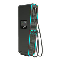
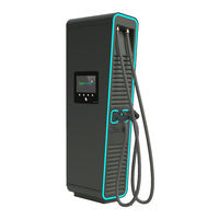
Alpitronic Hypercharger HYC 300 Manuals
Manuals and User Guides for Alpitronic Hypercharger HYC 300. We have
3
Alpitronic Hypercharger HYC 300 manuals available for free PDF download: Operation Instructions And Installation Manual, User Manual
Alpitronic Hypercharger HYC 300 Operation Instructions And Installation Manual (105 pages)
ultra-fast charging system for electric vehicles
Brand:
Alpitronic
| Category:
Battery Charger
| Size: 9.35 MB
Table of Contents
Table of Contents
6
1 Safety Instructions
12
Designated Use
12
Users
12
Safety Instructions for Installation and Maintenance
13
2 Product Description
15
Table 1: Overview DC Power and Options of the Hypercharger Product Family
15
Figure 2: Configuration HYC_300
16
Figure 3: Order of Charging Points HYC_150 and HYC_300
16
Charging Interfaces
17
Table 2: Charging Interfaces
17
Table 3: Additional Charging Interfaces for Automotive Multichargers
17
Table 4: Possible Combinations of Charging Interfaces
18
Figure 4: DC-Power Characteristic in Different Configurations
19
Figure 5: Cable Reach for the Two DC Outlets of the Hypercharger
20
Exterior View
21
Figure 6: Elements of the Charging Station HYC_150 and HYC_300
21
Figure 7: External Dimensions HYC_150 (in MM)
22
Figure 8: External Dimensions HYC_300 (in MM)
22
2.2.1. Nameplate
23
Opening of the Hypercharger
23
Figure 9: Example of Nameplate for Hypercharger HYC_300
23
Figure 10: Half Cylinder (Data in MM)
23
Figure 11: Order for Opening the Hypercharger Doors
24
Figure 12: Locking Mechanism for the Display Door
24
Internal View
25
2.4.1. HYC_150 Internal View
25
Figure 13: Internal View Hypercharger HYC_150 (Service-, Display-, Charging Cable Side)
25
Table 5: Hypercharger HYC_150 Cabinet Components
26
2.4.2. HYC_300 Internal View
27
Figure 14: Internal View Hypercharger HYC_300 (Service-, Display- and Charging Cable-Side)
27
Table 6: Hypercharger HYC_300 Cabinet Components
28
Main Components
29
Power-Stack
29
Figure 15: Dimensions of Power-Stack
29
Figure 16: AC Connection Block
30
Figure 17: DC Connection Block
30
Figure 18: Status Indication of Power-Stack
31
Table 7: Technical Data
31
Table 8: Mechanical Data
31
Table 9: Electrical Data AC Connection
32
Table 10: Electrical Data DC Connection
32
Input Switchgear
33
Figure 19: AC Input Switchgear of the HYC_150
33
Table 11: AC Input Switchgear Components for Hypercharger HYC_150
33
Figure 20: AC Input Switchgear of the HYC_300
34
Table 12: AC Input Switchgear Components for Hypercharger HYC_300
34
Output Switchgear
35
Figure 21: Input Switchgear Hyc_300_F with Fuses (Optional)
35
Figure 22: DC Output Switchgear of the HYC_150 (Bottom View)
35
Figure 23: DC Output Switchgear of the HYC_150 (Top View)
36
Table 13: DC Output Switchgear Components for Hypercharger HYC_150
36
Figure 24: DC Output Switchgear of the HYC_300 (Bottom View)
37
Figure 25: DC Output Switchgear of the HYC_300 (Top View)
37
Table 14: DC Output Switchgear Components for Hypercharger HYC_300
38
Ctrl_Com
39
Figure 26: Location of the CTRL_COM in the Hypercharger
39
Display Incl. RFID Reader
41
Figure 28: Display Module
41
Table 15: Display Properties
41
Ctrl_Ext
42
Figure 29: Location of the CTRL_EXT in the Hypercharger
42
Additional Options
43
Cooling Unit
43
Figure 30: Cooling Unit for Cooled Charging Cable (Optional)
43
Emergency Stop Button
44
External Emergency Stop Relay
44
Figure 31: Location of the Relais in the Hypercharger
44
Figure 32: Connection Options External Emergency Stop
45
Crash Sensors
46
Door Contact Switches
46
Credit Card Terminal
46
Figure 33: Contactless Credit Card Terminal (Model COR A20)
46
Barrier-Free Hypercharger
47
Figure 34: Barrier-Free Hypercharger
47
3 Packaging, Transport and Storage
48
Packaging
48
Figure 35: Packaging of the Hypercharger
48
Table 16: Dimensions of the Packaging
48
Transport and Storage
49
Figure 36: Vertical Transport with Pallet Truck or Forklift
49
Table 17: Maximum Weight and Threat Size for Eyebolts for Different Hypercharger Product Types
49
Figure 37: Crane Eyelets on Top of the Packaging
50
Unpacking
51
Figure 38: Unpacking the Hypercharger
52
4 Hypercharger Installation and Commissioning
53
Mechanical Installation of the Hypercharger
53
Figure 39: Relevant Components for the Mechanical Installation of the Hypercharger
53
Site Configuration
54
Table 18: Distances
54
Figure 40: Recommended Distances for Site Configuration
55
Figure 41: Hypercharger Concrete Foundation
56
Placement of a Concrete Foundation
56
Figure 42: Backfill of the Foundation
57
Figure 43: Hypercharger Base
58
Figure 44: Hypercharger Base for the HYC_150 (Dimensions in MM)
58
Mounting the Hypercharger Base on the Foundation
58
Figure 45: Hypercharger Base for the HYC_300 (Dimensions in MM)
59
Figure 46: Position of the HYC_150 (Blue) and HYC_300 (Red) Base on the Foundation
60
Figure 47: Alignment of the Base and Cable Entry Plates on the Foundation
60
Figure 48: Distances between the Base and the Outer Dimensions of the HYC_150 (Top View)
61
Mounting the Hypercharger on the Base Plate
62
Table 19: Distances between Base Plate and Outer Dimensions of Charging Station
62
Electrical Installation
63
Hypercharger Schematic HYC_150
63
Figure 27: CTRL_COM
63
Hypercharger Schematic HYC_300
64
Preparation Mains Power-Supply Cables
65
Table 20: Available Cable Entry Plates for Hypercharger Base
65
Grid Connection
67
Table 21: Recommended Conductor Cross Sections
69
Overvoltage Protection
70
Checks before Initial Startup
71
Table 22: Checks to be Carried out before Commissioning
71
Commissioning Protocol
72
5 Diagnosis and Parameterization
75
Table 23: Default Charging Station IP Address
75
6 Operating the Hypercharger
76
Start Charging Session
76
Authentication
76
Select the Charging Plug
78
Connect the Plug
80
During the Charging Process
81
Charging Overview
81
Terminate Charging Session
83
Leaving Screen Saving Mode
83
Charging Stop
83
Procedure for Error Messages
84
Authorization Failed
84
No Connector Available
84
Connector Damaged
85
Communication Error with Vehicle
85
Failed to Lock Connector
86
The Car Signalized an Error
86
Emergency Stop
87
Charging Station Temporarily Unavailable
87
7 Error Description and Solution
88
Table 24: Error Description and Troubleshooting
88
8 Maintenance
89
Overview of Maintenance Work
89
Table 25: Periodic Maintenance Work
89
Function Test of Circuit Breaker
90
Function Test of Main Switch
91
Verification of Protective Measures
91
Check for Cleanliness and Condensation
92
Check Charging Cable
92
Check Screws
92
Check Overvoltage Protection
93
Connectivity of Sim Cards
93
8.10. Change Filter Mats
94
8.11. Check Coolant
95
Check Coolant Level
95
Check Coolant Concentration
96
Check Coolant Ph
96
8.12. Close the Hypercharger
96
9 Repair and Service
97
10 Disposal
98
11 Technical Specifications
99
Table 26: Technical Data
99
Table 27: Mechanical Data
99
Table 28: Electrical Connection for HYC_150
99
Table 29: Electrical Connection for HYC_300
100
Table 30: Electrical Connection for Hyc_300_F
100
Table 31: Standby Power Consumption
101
Table 32: Frequency Bands and Transmission Levels of HYC_150 / HYC_300
101
12 Declaration of Conformity
102
Advertisement
Alpitronic Hypercharger HYC 300 Operation Instructions And Installation Manual (64 pages)
Ultra-fast charging system for electric vehicles
Brand:
Alpitronic
| Category:
Automobile Accessories
| Size: 5.78 MB
Table of Contents
Table of Contents
5
1 Safety Instructions
9
Designated Use
9
Users
9
Safety Instructions for Installation and Maintenance
9
Nameplate
12
Figure 1: Example of Nameplate for Hypercharger
12
2 Transport, Storage, Unpacking and Handling
13
Packaging
13
Transport, Handling and Storage
13
Table 1: Dimension of the Packaging
13
Figure 2: Vertical and Horizontal Transport with Pallet Truck or Forklift
14
Figure 3: Crane Eyelets on Top of the Packaging
14
Table 2: Maximum Weight and Threat Size for Eyebolts for the Whole Hypercharger Product Range
15
Unpacking
16
Figure 4: Unpacking the Hypercharger
17
3 Product Description
18
Exterior View
18
Figure 5: Elements of the Charging Station
18
Site Configuration
19
Figure 6: Recommended Distances for Site Configuration
19
Cable Reach
20
Figure 7: Cable Reach for the Two DC Outlets of the Hypercharger
20
Table 3: Distances to Keep Free for Service
20
Opening of the Hypercharger
21
Figure 8: Order for Opening the Hypercharger
21
Internal View
22
HYC_075 and HYC_150 Internal View
22
Figure 9: Internal View Hypercharger HYC_075 and HYC_150 (Left, Front and Right)
22
Table 4: Hypercharger HYC_075 and HYC_150 Cabinet Components
23
Figure 10: DC Output Switchgear of the HYC_075 and the HYC_150
24
Figure 11: AC Input Switchgear of the HYC_075 and the HYC_150
25
Table 5: DC Output Switchgear Components for Hypercharger HYC_075 and HYC_150
25
Table 6: AC Input Switchgear Components for Hypercharger HYC_075 and HYC_150
25
HYC_225 and HYC_300 Internal View
26
Figure 12: Internal View Hypercharger HYC_225 and HYC_300 (Left, Front and Right)
26
Figure 13: DC Output Switchgear of the HYC_225 and the HYC_300 (Bottom View)
27
Table 7: Hypercharger HYC_225 and HYC_300 Cabinet Components
27
Figure 14: DC Output Switchgear of the HYC_225 and the HYC_300 (Top View)
28
Table 8: DC Output Switchgear Components for Hypercharger HYC_225 and HYC_300
28
Figure 15: AC Input Switchgear of the HYC_225 and the HYC_300
29
Table 9: AC Input Switchgear Components for Hypercharger HYC_225 and HYC_300
29
Hypercharger Configurations
30
HYC_075 Configuration
30
Figure 16: Hypercharger Configurations and Options
30
HYC_150 Configuration
31
Figure 17: DC Output Power of the 75Kw Hypercharger
31
Figure 18: DC Output Power of the 150Kw Hypercharger, Whole DC-Power on One Outlet
31
HYC_225 Configuration
32
HYC_300 Configuration
32
Figure 19: DC Output Power of the 225Kw Hypercharger
32
Figure 20: DC Output Power of the 300Kw Hypercharger, Whole DC-Power on One Outlet
33
4 Mechanical Installation
34
Figure 21: Naming of Relevant Components for the Mechanical Installation of the Hypercharger
34
Concrete Foundation
35
Figure 22: Distances between Base Plate and Outer Dimensions of Charging Station on the Concrete Foundation (HYC_075, HYC_150) (Front/Top View)
35
Table 10: Distances between Base Plate and Outer Dimensions of Charging Station
35
Adaptor
36
Hypercharger-Base
36
Figure 23: Distances between Base Plate and Outer Dimensions of Charging Station on the Concrete Foundation (HYC_225, HYC_300) (Front/Top View)
36
Figure 24: Hypercharger-Base for the HYC_075 and HYC_150 (Front/Top View Left)
37
Figure 25: Hypercharger-Base for the HYC_225 and HYC_300 (Front/Top View Left)
37
Mechanical Installation of the Hypercharger
38
5 Electrical Installation
39
Hypercharger Schematic for the HYC_075 and the HYC_150
39
Figure 26: Hypercharger Schematic for the HYC_075 and the HYC_150
39
Hypercharger Schematic for the HYC_225 and the HYC_300
40
Figure 27: Hypercharger Schematic for the HYC_225 and the HYC_300
40
Preparation Mains Power-Supply Cables
41
Figure 28: Cable Inlet and Connection Lengths for HYC_075 to HYC_300
41
Table 11: Available Cable Entry Adaptor Plates for Hypercharger-Base (Not Available Yet)
41
Grid Connection
42
Figure 29: Connecting of the Input Busbars (HYC_075/150 Left, HYC_225/300 Right)
42
Checks before Initial Startup
43
Table 12: Checks to be Carried out before Commissioning
43
6 Diagnosis and Parameterization
44
User Interface
44
Figure 30: Credentials Form Shown at First Connection with Web Interface
44
Table 13: Default Charging Station IP Address
44
Table 14: Default Credentials to Web Interface
44
Figure 31: Home Screen of Web Interface
45
Diagnosis
47
Figure 32: Example of SIM Signal Webpage
47
Figure 33: Example of Process View Webpage
48
Figure 34: Example of Stop Button Webpage
49
Parameterization
50
Figure 35: Example of BOOT Configuration Webpage
50
Figure 36: Example of OCPP Configuration Webpage
51
Figure 37: Example of GUI Configuration Webpage
52
Figure 38: Example of Ethernet Configuration Webpage
53
Figure 39: Example of SIM Configuration Webpage
54
Figure 40: Example of the Password Configuration Webpage
54
7 Error Description and Removal
55
Table 15: Error Description and Troubleshooting
55
8 Maintenance
56
Overview of Maintenance Work
56
Table 16: Periodic Maintenance Work
56
Replacing a Hypercharger Power-Stack
57
Figure 41: Replacing a Power-Stack
57
Cooling Unit for Cooled Charging Cable (Optional)
58
Figure 42: Cooling Unit for Cooled Charging Cable (Option)
58
Table 17: Relation Frost Protection to Dilution Ratio
59
9 Technical Specifications
60
Table 18: Technical Data (General)
60
Table 19: Mechanical Data
60
Table 20: Electrical Connection for HYC_075
60
Table 21: Electrical Connection for HYC_150
61
Table 22: Electrical Connection for HYC_225
61
Table 23: Electrical Connection for HYC_300
61
10 Declaration of Conformity
62
Alpitronic Hypercharger HYC 300 User Manual (39 pages)
ultra-fast charging system for electric vehicles
Brand:
Alpitronic
| Category:
Battery Charger
| Size: 4.33 MB
Table of Contents
Table of Contents
3
Product Description
5
Figure 1: Sequence of Charging Points HYC_150 and HYC_300
5
Table 1: Overview DC Power and Options for the Hypercharger Product Family
5
Charging Interfaces
6
Table 2: Charging Interfaces
6
Exterior View
7
Figure 2: Elements of the HYC_150 and HYC_300 Charging Stations
7
Nameplate
8
Figure 3: Example of Nameplate for Hypercharger HYC_300
8
Start Charging Session
9
Authentication Options
9
Figure 4: Overview of the Authentication Options
9
Authentication
10
Figure 5: Authentication
10
Figure 6: Position of RFID Reader
11
Figure 7: Position of Credit Card Terminal
11
Figure 8: Kiosk Mode
12
Figure 9: Checking ID
12
Select the Charging Plug
13
Figure 10: Select Plug
13
Figure 11: Buttons for Navigation
13
Figure 12: Language Selection
14
Connect the Plug
15
Figure 13: Plug Connection
15
During the Charging Process
16
Charging Overview
16
Figure 14: Charging Overview
16
Figure 15: Charge Overview with Two Active Charging Processes
17
Terminate Charging Session
18
Leaving Screen Saving Mode
18
Charging Stop
18
Figure 16: Charging Stop
18
Figure 17: Disconnect Plug
18
Write down Public Key (German Calibration Law)
19
Figure 18: Charging Data Overlay
19
Figure 19: Public Key Overlay
19
Figure 20: Error Overlay
20
Error Messages
21
Authorization Failed
21
No Connector Available
21
Figure 21: Authorization Failed
21
Figure 22: no Connector Available
21
Connector Damaged
22
Communication Error with Vehicle
22
Figure 23: Connector Damaged
22
Figure 24: Communication Error
22
Failed to Lock Connector
23
The Car Signalized an Error
23
Figure 25: Failed to Lock Connector
23
Figure 26: Vehicle Error
23
Emergency Stop
24
Charging Station Temporarily Unavailable
24
Figure 27: Emergency Stop
24
Figure 28: Maintenance Ongoing
24
Advertisement
Advertisement
Related Products
Alpitronic Hypercharger HYC 075
Alpitronic Hypercharger HYC 150
Alpitronic Hypercharger HYC 225
Alpitronic Hypercharger HYC 50
Alpitronic Hypercharger HYC200
Alpitronic hypercharger HYC400
Alpitronic hypercharge HYC 50
Alpitronic Categories
Battery Charger
Automobile Battery Charger
Automobile Accessories
More Alpitronic Manuals
Login
Sign In
OR
Sign in with Facebook
Sign in with Google
Upload manual
Upload from disk
Upload from URL