Table of Contents
Advertisement
Quick Links
hypercharger - Operation Instructions and Installation Guide
Version 1-1C
Content
Operation Instructions and
Installation Guide
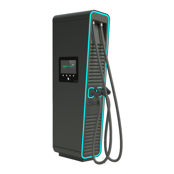
hypercharger 75kW – 300kW
(HYC_075 / HYC_150 / HYC_225 / HYC_300)
ultra-fast charging system for electric vehicles
for HW-Versions 2.x
All rights reserved. The reproduction of this document, also partially, is allowed only with authorization by alpitronic s.r.l.
Advertisement
Table of Contents

Related Manuals for Alpitronic Hypercharger HYC 075


Summary of Contents for Alpitronic Hypercharger HYC 075
- Page 1 Installation Guide hypercharger 75kW – 300kW (HYC_075 / HYC_150 / HYC_225 / HYC_300) ultra-fast charging system for electric vehicles for HW-Versions 2.x All rights reserved. The reproduction of this document, also partially, is allowed only with authorization by alpitronic s.r.l.
- Page 2 - Operation Instructions and Installation Guide Version 1-1C Content This page was intentionally left blank. All rights reserved. The reproduction of this document, also partially, is allowed only with authorization by alpitronic s.r.l.
- Page 3 Via di Mezzo ai Piani, 33 39100 Bolzano (BZ) ITALY Tel.: +39 0471 096450 Fax: +39 0471 096451 Homepage: http://www.hypercharger.it E-Mail: info@hypercharger.it All rights reserved. The reproduction of this document, also partially, is allowed only with authorization by alpitronic s.r.l.
- Page 4 First version 1-1B May 2018 Ch. Leimegger Revision and extension to HY_225 and HY_300 1-1C June 2018 Ch. Leimegger Correction and extension All rights reserved. The reproduction of this document, also partially, is allowed only with authorization by alpitronic s.r.l.
-
Page 5: Table Of Contents
Replacing a hypercharger power-stack ..............49 8.3. Cooling unit for cooled charging cable (optional) ............50 9. Technical specifications....................52 Declaration of Conformity ..................54 All rights reserved. The reproduction of this document, also partially, is allowed only with authorization by alpitronic s.r.l. - Page 6 Figure 40: Example of the Password Configuration webpage ...........46 Figure 41: Replacing a Power-Stack .................49 Figure 42: Cooling unit for cooled charging cable (option) ..........50 All rights reserved. The reproduction of this document, also partially, is allowed only with authorization by alpitronic s.r.l.
- Page 7 Table 20: Electrical connection for HYC_075 ..............52 Table 21: Electrical connection for HYC_150 ..............53 Table 22: Electrical connection for HYC_225 ..............53 Table 23: Electrical connection for HYC_300 ..............53 All rights reserved. The reproduction of this document, also partially, is allowed only with authorization by alpitronic s.r.l.
- Page 8 - Operation Instructions and Installation Guide Version 1-1C Content This page was intentionally left blank. All rights reserved. The reproduction of this document, also partially, is allowed only with authorization by alpitronic s.r.l.
-
Page 9: Safety Instructions
Disregards from these instructions can lead to serious or fatal personal injury, as well as serious damage to property. All rights reserved. The reproduction of this document, also partially, is allowed only with authorization by alpitronic s.r.l. - Page 10 Crushing Please take care when assembling and disassembling components that they do not squeeze a human body or body part. All rights reserved. The reproduction of this document, also partially, is allowed only with authorization by alpitronic s.r.l.
- Page 11 To turn off the hypercharger, one can find the main switch (see Figure 26) in the cabinet, rotate the handle to position ‘0’. This will turn off all the main components of the hypercharger. All rights reserved. The reproduction of this document, also partially, is allowed only with authorization by alpitronic s.r.l.
-
Page 12: Nameplate
50 (±5%) Maximal input current: Degree of protection: IP54 Charging voltage range: 150…1000 Max. Weight: Figure 1: Example of Nameplate for hypercharger All rights reserved. The reproduction of this document, also partially, is allowed only with authorization by alpitronic s.r.l. -
Page 13: Transport, Storage, Unpacking And Handling
It can be transported in ordinary trucks as well as in vans (horizontal position during transport). All rights reserved. The reproduction of this document, also partially, is allowed only with authorization by alpitronic s.r.l. -
Page 14: Figure 2: Vertical And Horizontal Transport With Pallet Truck Or Forklift
Figure 3: Crane eyelets on top of the packaging All rights reserved. The reproduction of this document, also partially, is allowed only with authorization by alpitronic s.r.l. -
Page 15: Table 2: Maximum Weight And Threat Size For Eyebolts For The Whole Hypercharger Product Range
[kg] for eyebolts HYC_075 HYC_150 HYC_225 HYC_300 Table 2: Maximum weight and threat size for eyebolts for the whole hypercharger product range All rights reserved. The reproduction of this document, also partially, is allowed only with authorization by alpitronic s.r.l. -
Page 16: Unpacking
Remove screws Remove rear panel Open left Remove screws on panels between panel side door the base plate of the and pallet hypercharger All rights reserved. The reproduction of this document, also partially, is allowed only with authorization by alpitronic s.r.l. -
Page 17: Figure 4: Unpacking The Hypercharger
Figure 4: Unpacking the hypercharger The outer packaging is made of 100% recyclable wood, the inner packaging is made of plastic and must be disposed separately. All rights reserved. The reproduction of this document, also partially, is allowed only with authorization by alpitronic s.r.l. -
Page 18: Product Description
The following figure shows the different connections of the device from the outside. Figure 5: Elements of the charging station DC charge outlet 1 DC charge outlet 2 (optional) AC charge socket (optional) All rights reserved. The reproduction of this document, also partially, is allowed only with authorization by alpitronic s.r.l. -
Page 19: Site Configuration
The figure above shows the hypercharger housing for the HYC_075 and the HYC_150, the distances for the HYC_225 and the HYC_300 can be found in the following table. All rights reserved. The reproduction of this document, also partially, is allowed only with authorization by alpitronic s.r.l. -
Page 20: Cable Reach
(3m) of the cables for the two DC outlets of the hypercharger. Figure 7: Cable reach for the two DC outlets of the hypercharger All rights reserved. The reproduction of this document, also partially, is allowed only with authorization by alpitronic s.r.l. -
Page 21: Opening Of The Hypercharger
2° open door on the right 3° open door in the middle 1° open door on the left Figure 8: Order for opening the hypercharger All rights reserved. The reproduction of this document, also partially, is allowed only with authorization by alpitronic s.r.l. -
Page 22: Internal View
32A circuit breaker with fault current monitoring AC charging / 4P -FB2 16A circuit breaker for auxiliary 230Vac / 4P -KF1, -KF2 CTRL_COM_HD control board, CTRL_COM Display All rights reserved. The reproduction of this document, also partially, is allowed only with authorization by alpitronic s.r.l. -
Page 23: Table 4: Hypercharger Hyc_075 And Hyc_150 Cabinet Components
DC charge outlet 2 (optional) -XD7 AC socket (optional, only when AC-socket is present) -XF1 Ethernet network-dose Table 4: hypercharger HYC_075 and HYC_150 cabinet components All rights reserved. The reproduction of this document, also partially, is allowed only with authorization by alpitronic s.r.l. -
Page 24: Figure 10: Dc Output Switchgear Of The Hyc_075 And The Hyc_150
DC-outlet 1 isolation monitoring device (optional, only when DC-outlet 2 is -BX2.2, -BX1.2 present) -FC1.1, FC1.2 DC-outlet 1 fuses -FC2.1, FC2.2 DC-outlet 2 fuses All rights reserved. The reproduction of this document, also partially, is allowed only with authorization by alpitronic s.r.l. -
Page 25: Figure 11: Ac Input Switchgear Of The Hyc_075 And The Hyc_150
Auxiliary 24V power supply -XD1 Mains input busbars -XF1 Ethernet network dose RJ45 Table 6: AC input switchgear components for hypercharger HYC_075 and HYC_150 All rights reserved. The reproduction of this document, also partially, is allowed only with authorization by alpitronic s.r.l. -
Page 26: Hyc_225 And Hyc_300 Internal View
125A circuit breaker / 3P / 16kA -QA3, -QA4 -QB1 500A main switch / 4P -QB2, -QB3 DC-outlet contactors -QB4, -QB5, Contactors for internal DC link -QB6 All rights reserved. The reproduction of this document, also partially, is allowed only with authorization by alpitronic s.r.l. -
Page 27: Figure 13: Dc Output Switchgear Of The Hyc_225 And The Hyc_300 (Bottom View)
The following figure shows the DC-output switchgear of the HYC_225 and the HYC_300: Figure 13: DC output switchgear of the HYC_225 and the HYC_300 (bottom view) All rights reserved. The reproduction of this document, also partially, is allowed only with authorization by alpitronic s.r.l. -
Page 28: Figure 14: Dc Output Switchgear Of The Hyc_225 And The Hyc_300 (Top View)
DC-busbar – pole for vehicle cable connection XD6 (DC-outlet 2) -XD4.2 Table 8: DC output switchgear components for hypercharger HYC_225 and HYC_300 All rights reserved. The reproduction of this document, also partially, is allowed only with authorization by alpitronic s.r.l. -
Page 29: Figure 15: Ac Input Switchgear Of The Hyc_225 And The Hyc_300
Auxiliary 24V power supply -XD1 Mains input busbars -XF1 Ethernet network dose Table 9: AC input switchgear components for hypercharger HYC_225 and HYC_300 All rights reserved. The reproduction of this document, also partially, is allowed only with authorization by alpitronic s.r.l. -
Page 30: Hypercharger Configurations
In addition, it is possible to have one 22kW AC socket installed. The following figure shows the DC output power of the 75kW hypercharger: All rights reserved. The reproduction of this document, also partially, is allowed only with authorization by alpitronic s.r.l. -
Page 31: Hyc_150 Configuration
The following figure shows the DC output power of the 150kW hypercharger, where the whole power is switched to one DC-outlet: Figure 18: DC output power of the 150kW hypercharger, whole DC-power on one outlet All rights reserved. The reproduction of this document, also partially, is allowed only with authorization by alpitronic s.r.l. -
Page 32: Hyc_225 Configuration
22kW AC socket installed. The following figure shows the DC output power of the 300kW hypercharger, where the whole power is switched to one DC-outlet: All rights reserved. The reproduction of this document, also partially, is allowed only with authorization by alpitronic s.r.l. -
Page 33: Figure 20: Dc Output Power Of The 300Kw Hypercharger, Whole Dc-Power On One Outlet
Due to the modular concept, variants may also occur in which e.g. in a HYC_300 only one or two stacks are installed. In this case, the DC output power is correspondingly different. All rights reserved. The reproduction of this document, also partially, is allowed only with authorization by alpitronic s.r.l. -
Page 34: Mechanical Installation
The mechanical mounting of the hypercharger to the concrete foundation can be performed either directly or via an adaptor if the foundation is a universal foundation. All rights reserved. The reproduction of this document, also partially, is allowed only with authorization by alpitronic s.r.l. -
Page 35: Concrete Foundation
519 mm (± 3 mm) 516 mm (± 3 mm) Table 10: Distances between base plate and outer dimensions of charging station All rights reserved. The reproduction of this document, also partially, is allowed only with authorization by alpitronic s.r.l. -
Page 36: Adaptor
The hypercharger-base needs a gap of 50mm from the ground level facilitate the connection of the mains-side supply cables. The following figure shows the hypercharger-base for the HYC_075 and the HYC_150: All rights reserved. The reproduction of this document, also partially, is allowed only with authorization by alpitronic s.r.l. -
Page 37: Figure 24: Hypercharger-Base For The Hyc_075 And Hyc_150 (Front/Top View Left)
The screws are to be tightened with a torque of 90Nm. For the hypercharge-base different cable entry adaptor-plates are available to enable different mains power-supply cables (details in chapter 5.3). All rights reserved. The reproduction of this document, also partially, is allowed only with authorization by alpitronic s.r.l. -
Page 38: Mechanical Installation Of The Hypercharger
The screws are to be tightened with a torque of 90Nm. It’s preferable to use self-locking thread lock washers. Connect the mains power-supply (see chapter 5.4) All rights reserved. The reproduction of this document, also partially, is allowed only with authorization by alpitronic s.r.l. -
Page 39: Electrical Installation
400V ~ 10kA (option) lightning -XF1 -XD2 protection Power socket 230Vac Ethernet (RJ45) Figure 26: hypercharger schematic for the HYC_075 and the HYC_150 All rights reserved. The reproduction of this document, also partially, is allowed only with authorization by alpitronic s.r.l. -
Page 40: Hypercharger Schematic For The Hyc_225 And The Hyc_300
400V ~ 10kA (option) lightning -XF1 -XD2 protection Power socket 230Vac Ethernet (RJ45) Figure 27: hypercharger schematic for the HYC_225 and the HYC_300 All rights reserved. The reproduction of this document, also partially, is allowed only with authorization by alpitronic s.r.l. -
Page 41: Preparation Mains Power-Supply Cables
Afterwards the M12 cable lugs can be mounted on the positions defined in Figure 28. Figure 28: Cable inlet and connection lengths for HYC_075 to HYC_300 All rights reserved. The reproduction of this document, also partially, is allowed only with authorization by alpitronic s.r.l. -
Page 42: Grid Connection
If an active cooled Cable is used (option), the cooling unit for cooled charging cable should be removed during grid connection (see 8.3.). All rights reserved. The reproduction of this document, also partially, is allowed only with authorization by alpitronic s.r.l. -
Page 43: Checks Before Initial Startup
Automatic shutdown of the the requirements of IEC 60364-4-41, section 411 must be met power supply Table 12: Checks to be carried out before commissioning All rights reserved. The reproduction of this document, also partially, is allowed only with authorization by alpitronic s.r.l. -
Page 44: Diagnosis And Parameterization
Default Credentials Username admin Password admin123 Table 14: Default Credentials to web interface All rights reserved. The reproduction of this document, also partially, is allowed only with authorization by alpitronic s.r.l. -
Page 45: Figure 31: Home Screen Of Web Interface
To check the status of the Stop Button, you can navigate to ‘STATUS’ from the main menu and then following the top menu ‘Stop Button’ can be found. All rights reserved. The reproduction of this document, also partially, is allowed only with authorization by alpitronic s.r.l. - Page 46 ‘SIM Configuration’ can be found. ‘PASS’ found on the main menu, is used to change the username and password for this web interface. All rights reserved. The reproduction of this document, also partially, is allowed only with authorization by alpitronic s.r.l.
-
Page 47: Diagnosis
Click on ‘STATUS’ from the main menu and following the top menu click on ‘Processes View’. Figure 33 is an example of the webpage, note that the webpage automatically refreshes and has a timestamp. All rights reserved. The reproduction of this document, also partially, is allowed only with authorization by alpitronic s.r.l. -
Page 48: Figure 33: Example Of Process View Webpage
This feature is optional and many not be present in all Charging Stations. All rights reserved. The reproduction of this document, also partially, is allowed only with authorization by alpitronic s.r.l. -
Page 49: Figure 34: Example Of Stop Button Webpage
- Operation Instructions and Installation Guide Version 1-1C 6 Diagnosis and parameterization Page 41 of 57 Figure 34: Example of Stop Button webpage All rights reserved. The reproduction of this document, also partially, is allowed only with authorization by alpitronic s.r.l. -
Page 50: Parameterization
Figure 35: Example of BOOT Configuration webpage All rights reserved. The reproduction of this document, also partially, is allowed only with authorization by alpitronic s.r.l. -
Page 51: Figure 36: Example Of Ocpp Configuration Webpage
Figure 36 is an example of the webpage, there is also present a comment next to each option. Figure 36: Example of OCPP Configuration webpage All rights reserved. The reproduction of this document, also partially, is allowed only with authorization by alpitronic s.r.l. -
Page 52: Figure 37: Example Of Gui Configuration Webpage
Figure 38 is an example of the webpage, please write only number and ‘.’ in the input fields otherwise a wrong configuration could be loaded. All rights reserved. The reproduction of this document, also partially, is allowed only with authorization by alpitronic s.r.l. -
Page 53: Figure 38: Example Of Ethernet Configuration Webpage
- Operation Instructions and Installation Guide Version 1-1C 6 Diagnosis and parameterization Page 45 of 57 Figure 38: Example of Ethernet Configuration webpage All rights reserved. The reproduction of this document, also partially, is allowed only with authorization by alpitronic s.r.l. -
Page 54: Figure 39: Example Of Sim Configuration Webpage
Used to change the password to access the web interface. Credentials should be changed after first login. Location: Click on ‘PASS’ from the main menu. Figure 40: Example of the Password Configuration webpage All rights reserved. The reproduction of this document, also partially, is allowed only with authorization by alpitronic s.r.l. -
Page 55: Error Description And Removal
Boot the charging station in charging station diagnostics mode and use the diagnostic tool for further fault localization Table 15: Error description and troubleshooting All rights reserved. The reproduction of this document, also partially, is allowed only with authorization by alpitronic s.r.l. -
Page 56: Maintenance
In this case, no complete replacement is necessary, the change of the majority is sufficient to ensure protection again. Table 16: Periodic maintenance work All rights reserved. The reproduction of this document, also partially, is allowed only with authorization by alpitronic s.r.l. -
Page 57: Replacing A Hypercharger Power-Stack
Figure 41: Replacing a Power-Stack Attention A Power Stack weights up to 95kg. Use a lifting tool for the replacement. All rights reserved. The reproduction of this document, also partially, is allowed only with authorization by alpitronic s.r.l. -
Page 58: Cooling Unit For Cooled Charging Cable (Optional)
To facilitate the electrical installation of the hypercharger, the cooling unit can be removed during grid connection (see 5.4) All rights reserved. The reproduction of this document, also partially, is allowed only with authorization by alpitronic s.r.l. -
Page 59: Table 17: Relation Frost Protection To Dilution Ratio
When filling the system, make sure that there are no air cushions in the cooling system that reduce the cooling capacity. All rights reserved. The reproduction of this document, also partially, is allowed only with authorization by alpitronic s.r.l. -
Page 60: Technical Specifications
400Vac +N +PE (±10%) Frequency 50Hz (±5%) Nominal current max. 250A Maximum protection (backup) 355A gG Connection terminals cross section connecting bolt 12mm All rights reserved. The reproduction of this document, also partially, is allowed only with authorization by alpitronic s.r.l. -
Page 61: Table 21: Electrical Connection For Hyc_150
2x12mm Rated peak withstand current I 10kA (peak) Rated short-time withstand current I 4kA (rms) Table 23: Electrical connection for HYC_300 All rights reserved. The reproduction of this document, also partially, is allowed only with authorization by alpitronic s.r.l. -
Page 62: Declaration Of Conformity
- Operation Instructions and Installation Guide Version 1-1C 10 Declaration of Conformity Page 54 of 57 Declaration of Conformity All rights reserved. The reproduction of this document, also partially, is allowed only with authorization by alpitronic s.r.l. - Page 63 - Operation Instructions and Installation Guide Version 1-1C 10 Declaration of Conformity Page 55 of 57 All rights reserved. The reproduction of this document, also partially, is allowed only with authorization by alpitronic s.r.l.
- Page 64 - Operation Instructions and Installation Guide Version 1-1C 10 Declaration of Conformity Page 56 of 57 All rights reserved. The reproduction of this document, also partially, is allowed only with authorization by alpitronic s.r.l.
Need help?
Do you have a question about the Hypercharger HYC 075 and is the answer not in the manual?
Questions and answers
how often should the coolant be checked?