Sign In
Upload
Manuals
Brands
Allen-Bradley Manuals
Controller
PowerFlex 525
Allen-Bradley PowerFlex 525 Manuals
Manuals and User Guides for Allen-Bradley PowerFlex 525. We have
10
Allen-Bradley PowerFlex 525 manuals available for free PDF download: Original Instructions Manual, User Manual, Quick Start Manual, Application Technique, Installation Instructions
Allen-Bradley
PowerFlex 525
User Manual
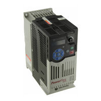
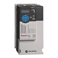
Allen-Bradley PowerFlex 525 - Adjustable Frequency AC Drive Manual
Brand:
Allen-Bradley
| Category:
Controller
| Size: 2.27 MB
Table of Contents
Mounting Considerations
Minimum Mounting Clearances
Ambient Operating Temperatures
Drive Dimensions
PowerFlex 525 Frames
IP20/Open Type
EMC Filters
Fuses and Circuit Breakers
Power Wiring
Power Terminal Block
Power Terminal Block Specifications
Control Terminal Block
General Grounding Requirements
Prepare For Drive Start-Up
LCD Display with QuickView Technology
AppView Parameter Groups
CustomView Parameter Group
Fault Codes
Specifications
Rockwell Automation Support
Documents / Resources
References
Advertisement
Allen-Bradley PowerFlex 525 Original Instructions Manual (244 pages)
Adjustable Frequency AC Drive
Brand:
Allen-Bradley
| Category:
DC Drives
| Size: 22.01 MB
Table of Contents
Table of Contents
5
Preface
9
Who Should Use this Manual
9
Recommended Documentation
9
Manual Conventions
10
Drive Frame Sizes
11
General Precautions
12
Catalog Number Explanation
13
Installation/Wiring
15
Mounting Considerations
15
AC Supply Source Considerations
19
General Grounding Requirements
20
Fuses and Circuit Breakers
22
Power and Control Module
27
Control Module Cover
30
Power Module Terminal Guard
30
Power Wiring
31
Power Terminal Block
34
Common Bus/Precharge Notes
35
I/O Wiring
35
Control I/O Terminal Block
36
Start and Speed Reference Control
46
CE Conformity
49
Start up
55
Prepare for Drive Start-Up
55
Display and Control Keys
58
Viewing and Editing Parameters
59
Drive Programming Tools
60
Language Support
60
Smart Start-Up with Basic Program Group Parameters
61
LCD Display with Quickview
63
Using the USB Port
63
Programming and Parameters
65
About Parameters
65
Parameter Groups
66
Basic Display Group
71
Basic Program Group
76
Terminal Block Group
82
Communications Group
94
Logic Group
100
Advanced Display Group
103
Advanced Program Group
107
Network Parameter Group
130
Modified Parameter Group
130
Fault and Diagnostic Group
130
Default
131
Values Default
133
Display
134
Values Default
134
Min/Max
135
Display
135
Appview Parameter Groups
138
Customview Parameter Group
139
Parameter Cross Reference by Name
140
Drive Status
145
Faults
145
Fault Descriptions
147
Common Symptoms and Corrective Actions
150
Certifications
155
Environmental Specifications
156
Technical Specifications
157
Power Specifications
160
Product Selection
163
Product Dimensions
173
Optional Accessories and Kits
186
Network Wiring
189
Parameter Configuration
190
Supported Modbus Function Codes
191
Writing (06) Logic Command Data
191
Writing (06) Comm Frequency Command
193
Reading (03) Logic Status Data
193
Reading (03) Drive Error Codes
195
Reading (03) Drive Operational Values
196
Reading (03) and Writing (06) Drive Parameters
196
Additional Information
196
Velocity Steplogic Using Timed Steps
198
Velocity Steplogic Using Basic Logic Functions
198
Timer Function
199
Counter Function
200
Velocity Steplogic Parameters
201
Encoder and Pulse Train Usage
203
Wiring Notes
204
Positioning Overview
205
Common Guidelines for All Applications
205
Positioning Operation
206
Homing Routine
210
Encoder and Position Feedback
211
Use over Communications
212
Setup Notes
213
PID Loop
215
PID Reference and Feedback
217
Analog PID Reference Signals
218
Powerflex 525 Safe-Torque-Off Overview
223
EC Type Examination Certification
224
EMC Instructions
224
Using Powerflex 525 Safe-Torque-Off
224
Safety Concept
225
Enabling Powerflex 525 Safe-Torque-Off
227
Wiring
227
Powerflex 525 Safe-Torque-Off Operation
227
Verify Operation
228
Connection Examples
229
Powerflex 525 Certification for Safe-Torque-Off
233
Establishing a Connection with Ethernet/Ip
235
Induction Motor Tuning Diagrams
237
Adjusting Speed Control Parameters
238
Allen-Bradley PowerFlex 525 User Manual (228 pages)
Adjustable Frequency AC Drive
Brand:
Allen-Bradley
| Category:
Controller
| Size: 18.19 MB
Table of Contents
Important User Information
2
Table of Contents
3
Overview
7
Preface
7
Recommended Documentation
7
Who Should Use this Manual
7
Manual Conventions
8
Drive Frame Sizes
9
General Precautions
9
Catalog Number Explanation
10
Chapter 1
11
Installation/Wiring
11
Mounting Considerations
11
AC Supply Source Considerations
15
General Grounding Requirements
16
Fuses and Circuit Breakers
18
Power and Control Module
22
Control Module Cover
25
Power Module Terminal Guard
25
Power Wiring
26
Power Terminal Block
29
Common Bus/Precharge Notes
30
I/O Wiring
30
Control I/O Terminal Block
32
Start and Speed Reference Control
39
CE Conformity
41
Chapter 2
47
Prepare for Drive Start-Up
47
Start up
47
Display and Control Keys
49
Viewing and Editing Parameters
50
Drive Programming Tools
51
Language Support
51
Smart Start-Up with Basic Program Group Parameters
52
LCD & Scrolling Description
53
Usb
54
Programming and Parameters
57
About Parameters
58
Chapter 3 Programming and Parameters about Parameters
58
Parameter Groups
58
Basic Display Group
63
Basic Program Group
68
Terminal Block Group
73
Communications Group
85
Logic Group
91
Advanced Display Group
94
Advanced Program Group
98
Modified Parameter Group
118
Network Parameter Group
118
Fault and Diagnostic Group
119
Appview Parameter Groups
126
Customview Parameter Group
127
Parameter Cross Reference by Name
128
Chapter 4
133
Drive Status
133
Faults
133
Fault Descriptions
135
Common Symptoms and Corrective Actions
138
Drives, Fuse & Circuit Breaker Ratings
143
Appendix A Specifications
144
Product Selection
149
Appendix B
157
Product Dimensions
157
Optional Accessories and Kits
170
Appendix C
173
Network Wiring
173
Parameter Configuration
174
Supported Modbus Function Codes
175
Writing (06) Logic Command Data
175
Reading (03) Logic Status Data
177
Writing (06) Comm Frequency Command
177
Reading (03) Drive Error Codes
179
Additional Information
180
Reading (03) and Writing (06) Drive Parameters
180
Reading (03) Drive Operational Values
180
Appendix D
182
Velocity Steplogic Using Basic Logic Functions
182
Velocity Steplogic Using Timed Steps
182
Timer Function
183
Counter Function
184
Velocity Steplogic Parameters
185
Rockwell Automation Publication 520-UM001A-EN-E - February
186
Encoder and Pulse Train Usage
187
Appendix E
188
Wiring Notes
188
Common Guidelines for All Applications
189
Positioning Overview
189
Positioning Operation
190
Homing Routine
194
Encoder and Position Feedback
195
Use over Communications
196
Setup Notes
197
Appendix F
199
PID Loop
199
Analog PID Reference Signals
201
PID Reference and Feedback
201
Powerflex 525 Safe-Torque-Off Overview
207
Appendix G
208
EC Type Examination Certification
208
EMC Instructions
208
Using Powerflex 525 Safe-Torque-Off
208
Safety Concept
209
Enabling Powerflex 525 Safe-Torque-Off
211
Powerflex 525 Safe-Torque-Off Operation
211
Wiring
211
Verify Operation
212
Connection Examples
213
Powerflex 525 Certification for Safe-Torque-Off
217
Appendix H
219
Establishing a Connection with Ethernet/Ip
219
Appendix I
221
Induction Motor Tuning Diagrams
221
Adjusting Speed Control Parameters
222
Advertisement
Allen-Bradley PowerFlex 525 User Manual (164 pages)
Embedded EtherNet/IP Adapter
Brand:
Allen-Bradley
| Category:
Adapter
| Size: 6.58 MB
Table of Contents
Important User Information
2
Table of Contents
3
Manual Conventions
7
Preface
7
Recommended Documentation
7
Chapter 1
9
Components
9
Features
10
Compatible Products
10
Required Equipment
10
Safety Precautions
12
Quick Start
12
Status Indicators
13
Chapter 2
15
Preparing for Set-Up
15
Setting the IP Address
16
Connecting the Adapter to the Network
16
Applying Power
17
Commissioning the Adapter
19
Configuration Tools
21
Chapter 3
22
Using the Drive Keypad Interface to Access Parameters
22
Using the Powerflex 4-Class HIM to Access Parameters
23
Using BOOTP
24
Setting the IP Address, Subnet Mask, and Gateway Address
27
Setting the Data Rate
28
Using Master-Slave Hierarchy
29
Setting a Fault Action
31
Resetting the Adapter
32
Viewing the Adapter Status Using Parameters
32
Chapter 4
35
Using Rslinx Classic
35
Compactlogix Example
36
Limitations in Using Micrologix 1100/1400
58
Chapter 5
59
About I/O Messaging
59
Understanding the I/O Image
59
Using Logic Command/Status
60
Using Reference/Feedback
61
Using Datalinks
61
Example Ladder Logic Program Information
62
Compactlogix Example
62
About Explicit Messaging
67
Chapter 6
68
Performing Explicit Messaging
68
Compactlogix Examples
68
Single-Drive Mode Vs. Multi-Drive Mode
81
Chapter 7
83
System Wiring
83
Understanding the I/O Image
83
Configuring the RS-485 Network
84
Using Multi-Drive Add-On Profile
85
Multi-Drive Ladder Logic Program for Generic Profile
95
Compactlogix Example Using Generic Profile
97
Multi-Drive Mode Explicit Messaging
105
Additional Information
106
Chapter 8
109
Understanding the Status Indicators
109
ENET Status Indicator
110
LINK Status Indicator
110
Viewing Adapter Diagnostic Items
110
Viewing and Clearing Events
112
Appendix A
115
Communication
115
Regulatory Compliance
115
Appendix B
117
Parameter List
117
Appendix C
123
Supported Data Types
123
Identity Object
124
Assembly Object
126
Register Object
127
Parameter Object
130
PCCC Object
132
DPI Device Object
135
DPI Parameter Object
138
Rockwell Automation Publication 520COM-UM001A-EN-E - February
139
DPI Fault Object
144
TCP/IP Interface Object
146
Ethernet Link Object
148
Logic Command Word
151
Appendix D
152
Logic Status Word
152
Powerflex 525 Drives Logic Status Word
152
Rockwell Automation Support
164
Documentation Feedback
164
Allen-Bradley PowerFlex 525 User Manual (140 pages)
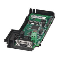
DeviceNet Adapter Catalog Number: 25-COMM-D
Brand:
Allen-Bradley
| Category:
Adapter
| Size: 9.15 MB
Table of Contents
Important User Information
2
Table of Contents
3
Manual Conventions
7
Preface
7
Recommended Documentation
7
Chapter 1
9
Components
9
Features
10
Understanding Parameter Types
10
Compatible Products
11
Required Equipment
11
Safety Precautions
12
Quick Start
13
Chapter 2
15
Preparing for an Installation
15
Commissioning the Adapter
15
Topic Page
15
Connecting the Adapter to the Drive
17
Connecting the Adapter to the Network
19
Applying Power
20
Configuration Tools
23
Chapter 3
23
Using the Drive Keypad Interface to Access Parameters
23
Using the Powerflex 4-Class HIM to Access Parameters
25
Setting the Node Address
25
Setting the Data Rate
26
Setting the I/O Configuration
26
Using Master-Slave Hierarchy (Optional)
26
Selecting COS, Cyclic, or Polled I/O
28
Setting a Fault Action
29
Resetting the Adapter
30
Restoring Adapter Parameters to Factory Defaults
30
Viewing the Adapter Status Using Parameters
31
Updating the Adapter Firmware
31
Chapter 4
33
Using Rslinx Classic
33
Compactlogix Example
34
Chapter 5
47
About I/O Messaging
47
Understanding the I/O Image
48
Using Logic Command/Status
48
Using Reference/Feedback
48
Using Datalinks
49
Example Ladder Logic Program
50
Compactlogix Example
51
About Explicit Messaging
55
Chapter 6
56
Performing Explicit Messaging
56
Compactlogix Examples
56
Chapter 7
58
Chapter 7
59
Single-Drive Mode Vs. Multi-Drive Mode
69
System Wiring
71
Understanding the I/O Image
71
Configuring the RS-485 Network
72
Multi-Drive Ladder Logic Program Example
73
Compactlogix Example Using Generic Profile
74
Multi-Drive Mode Explicit Messaging
82
Additional Information
83
Chapter 8
85
Understanding the Status Indicators
85
PORT Status Indicator
86
MOD Status Indicator
86
NET a Status Indicator
87
Viewing Adapter Diagnostic Items
87
Viewing and Clearing Events
88
Appendix A
91
Communication
91
Electrical
91
Mechanical
91
Environmental
91
Regulatory Compliance
91
Appendix B Device Parameters
93
Appendix C
97
Supported Data Types
97
Identity Object
98
Assembly Object
100
Connection Object
101
Register Object
103
Parameter Object
106
Parameter Group Object
109
PCCC Object
111
DPI Device Object
114
DPI Parameter Object
117
DPI Fault Object
123
DPI Diagnostic Object
125
Logic Command Word
127
Appendix D
128
Logic Status Word
128
Powerflex 525 Drives Logic Status Word
128
Rockwell Automation Publication 520COM-UM002A-EN-E - April
129
Glossary
131
Glossary
132
Glossary
133
Glossary
134
Glossary
135
Glossary
136
Index
138
Rockwell Automation Support
140
Documentation Feedback
140
Allen-Bradley PowerFlex 525 Quick Start Manual (37 pages)
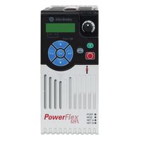
PowerFlex 520-Series Adjustable Frequency AC Drive
Brand:
Allen-Bradley
| Category:
Controller
| Size: 4.68 MB
Table of Contents
Additional Resources
1
General Precautions
2
Mounting Considerations
3
Minimum Mounting Clearances
3
Ambient Operating Temperatures
4
General Grounding Requirements
4
Ungrounded Distribution Systems
5
Fuses and Circuit Breakers
6
Technical Specifications
8
Power Wiring
9
Recommended Shielded Wire
9
Power Terminal Block Diagrams and Wiring Specifications
9
Input Power Conditions
9
I/O Wiring
10
Control Terminal Block
11
Powerflex 523 Control I/O Wiring Block Diagram
11
Powerflex 523 Control I/O Terminal Designations
12
Powerflex 525 Control I/O Wiring Block Diagram
13
Powerflex 525 Control I/O Terminal Designations
14
Prepare for Drive Start-Up
15
Before Applying Power to the Drive
15
Start, Stop, Direction, and Speed Control
16
Display, Control, and Navigation Keys
16
Viewing and Editing Parameters
17
Basic Display Group Parameters
18
Smart Start-Up with Basic Program Group Parameters
20
Advanced Program Group Parameters
22
Dimensions and Weight
32
Network Communication
33
Powerflex 520-Series RS784 (DSI) Protocol
33
Powerflex 525 Embedded Ethernet/Ip
34
Setting the IP Address, Subnet Mask, and Gateway Address
35
Important Information
36
Allen-Bradley PowerFlex 525 Original Instructions Manual (48 pages)
PowerFlex 520-Series AC Drive
Brand:
Allen-Bradley
| Category:
Controller
| Size: 4.21 MB
Table of Contents
Table of Contents
1
Product Overview
2
Catalog Number Explanation
8
Technical Specifications
9
Environmental Specifications
12
Certifications
13
Dimensions and Weights
14
Design Considerations
16
Allen-Bradley PowerFlex 525 Original Instructions Manual (44 pages)
Brand:
Allen-Bradley
| Category:
Controller
| Size: 6.04 MB
Table of Contents
Product Overview
2
Catalog Number Explanation
8
Technical Specifications
9
Environmental Specifications
11
Certifications
12
Dimensions and Weights
13
Design Considerations
15
Fuses and Circuit Breaker Ratings
25
Accessories and Dimensions
30
Safe-Torque-Off Function
39
Additional Resources
43
Allen-Bradley PowerFlex 525 Application Technique (24 pages)
Safety Function: Actuator Subsystems - Stop Category 1, Drives with Safe Torque-off
Brand:
Allen-Bradley
| Category:
DC Drives
| Size: 0.91 MB
Table of Contents
Table of Contents
1
Important User Information
2
General Safety Information
3
Introduction
3
Safety Function Realization: Risk Assessment
3
Stop Safety Functions
4
Safety Function Requirements
4
Functional Safety Description
5
Bill of Material
6
Setup and Wiring
6
Configuration
11
Calculation of the Performance Level
13
Verification and Validation Plan
17
Additional Resources
22
Allen-Bradley PowerFlex 525 Installation Instructions (2 pages)
Incremental Encoder Input
Brand:
Allen-Bradley
| Category:
Media Converter
| Size: 1.68 MB
Advertisement
Related Products
Allen-Bradley PowerFlex 523
Allen-Bradley PowerFlex 527
Allen-Bradley 5069 CompactLogix
Allen-Bradley 5069 Compact GuardLogix
Allen-Bradley GuardLogix 5570
Allen-Bradley SoftLogix 5800
Allen-Bradley ControlLogix 5580
Allen-Bradley 5069-L310ER-NSE
Allen-Bradley 5069-L320ERM
Allen-Bradley 5069-L340ERM
Allen-Bradley Categories
Control Unit
Controller
I/O Systems
Switch
Power Supply
More Allen-Bradley Manuals
Login
Sign In
OR
Sign in with Facebook
Sign in with Google
Upload manual
Upload from disk
Upload from URL