Sign In
Upload
Manuals
Brands
ABB Manuals
Laboratory Equipment
PGC5000 Series
ABB PGC5000 Series Manuals
Manuals and User Guides for ABB PGC5000 Series. We have
2
ABB PGC5000 Series manuals available for free PDF download: Service Instructions Manual, Service Instruction
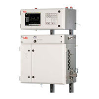
ABB PGC5000 Series Service Instructions Manual (88 pages)
Process Gas Chromatographs
Brand:
ABB
| Category:
Laboratory Equipment
| Size: 2.52 MB
Table of Contents
Table of Contents
3
1 Glossary
5
2 Safety and Symbols
6
3 Introduction
7
General
7
Drawings
7
Master Controller
7
Class B Oven
7
Liquid Version
8
Vapor Version
8
Class C Oven
8
Air Purge Systems
8
System Variations
8
4 Maintenance
9
Equipment and Supplies Required
9
Preventive Maintenance
9
Gas Cylinder Replacement
9
Cleaning
10
System Backup
10
USB Connectors
10
5 Diagnostics and Troubleshooting
11
General
11
Power-On Self Test
11
Indicator Boxes and Hex Codes
11
Power
13
Power Failure Recovery
13
Oven LED Indicators
13
System Board Battery
14
Board Level Light Emitting Diodes
14
Single Board Computer
14
Oven Controller Pcb
16
DTC Digital Pcb, Version 1
17
DTC Digital Pcb, Version 2
19
Detector Canbus Node Identification
20
Indicator Troubleshooting Procedures
21
Identifying Issues
21
Correcting Issues
21
Status Indicators
21
Operation Troubleshooting
27
Baseline Noise
27
Baseline or Signal Offset
27
No Peaks
28
Double Sampling
28
Mystery Peaks
28
Individual Peak Missing on Report
29
Chromatogram Oversized or off Scale
29
Variable Sample Size
29
Variable Retention Times
29
Reduced Peak Size
29
Loss of Power
29
Flame out LED on
30
Software
30
System Backup and Recovery
30
System Backup Error Messages
31
Restarting the Analyzer
32
Upgrading Software
33
Optional Discharge Ionization Detector
33
Plasma will Not Light
33
No Signal
33
Low Signal
34
Noisy
34
High Baseline
35
Drifting Baseline
35
Spikes
35
Shifting Retention Times
35
6 Component Repair
36
General
36
Preparation and Procedures
36
Electrostatic Discharge Information
36
Powering down the Analyzer System
36
Equipment and Supplies Required
36
Master Controller Cabinet
37
SBC and Card Cage Assembly
37
Oven Controller Pcb
38
Power Supply
38
Optional Wago Modules
38
Master Controller Cabinet Door
38
Front Panel Pcb
39
Liquid Crystal Display Assembly
39
Oven Component Locations
40
Class B Oven Components, V1
40
Class B Oven Components, V2
40
Class C Oven Components
41
Replacing the Epc Control Pcb
41
Replacing the Epc Control Assy
41
Preparation
41
Removing the Epc Control Assy
42
Installing the Epc Control Assy
43
Removing a Sensor Pcb
44
Installing a New Sensor Pcb
45
Removing a Proportional Valve
45
Installing a New Proportional Valve
46
Removing the Control Pcb
46
Installing a New Control Pcb
46
Removing the Heater
47
Installing a New Heater
47
FID Amplifier Assembly
47
FPD Electrometer
48
TCD Amplifier Assemblly
48
Replacing the Dtc Analog Pcb, V1
48
Replacing Optional Zone Board
49
Replacing Dtc Digital Pcb, V1
49
Replacing Oven Indicator Pcb
49
Replacing Dtc Master Analog Pcb, V2
49
Replacing Dtc Digital Pcb, V2
50
Replacing Dtc Auxiliary Pcb
50
Replacing Power Distribution Board
50
7 Subassembly Repair
52
Column Repair
52
Column Removal
52
Packed Column Installation
52
Capillary Column Installation
52
Cutting Capillary Columns
53
Repairing the Flame Ionization Detector
53
FID Cell Access
54
Replacing the Breather
54
Replacing the Thermocouple Assembly
54
Replacing the Polarizer
54
Replacing the Igniter Assembly
55
Cleaning the Fid Jet
55
Replacing the Fid Cable Assembly
56
Repairing the Single Port Tcd
56
Removing the Filaments
57
Installing the Filaments
57
Filament Checkout
57
Leak Test
58
Connecting the Filaments
58
Potting the Filaments
58
Re-Installing Mounting Bracket Cover
58
Repairing the Multiport Tcd
59
Accessing the Detector
59
Removing the Filaments
59
Installing New Filaments
59
Repairing the Flame Photometric Detector
61
Replacing the Photomultiplier Assembly
61
Replacing the Burner Block
61
Replacing the Burner Block O-Rings
62
Replacing the Jet
62
Liquid Sample Valve Repair
63
LSV Disassembly on the Analyzer
64
LSV Reassembly on the Analyzer
64
Removing LSV from the Analyzer
66
Installing LSV on the Analyzer
66
CP Valve Repair
67
Preparation and Safety
67
Replacing the Slider
67
Replacing the Wedges
68
Replacing the O-Rings
68
Replacing the Valve Plate
70
Replacing Diaphragm Valves
70
Preparation
70
Removing a Valve
71
Replacing the Diaphragm (4 Screw)
71
Replacing the Diaphragm (1 Screw)
72
Installing the New Diaphragm Valve
72
Optional Discharge Ionization Detector
73
Scheduled Maintenance
73
Removing the Detector
73
Installing the Detector
73
Replacing the Exhaust Tube
74
Replacing the Power Supply
74
8 Replacement Parts
75
Ordering Information
75
Equipment Identification
75
Master Controller Config Identification
75
Oven Configuration Identification
76
Software Configuration Identification
76
How to Order
76
Master Controller
77
Back of Door
77
Master Controller Chassis
77
Class B1 Oven Components
78
Left Side Components
78
Left Front Door Components
78
Class B2 Oven Components
79
Left Side Components
79
Left Front Door Components
79
Class B Main Interior Components
80
Liquid Sample Valve
81
Flame Ionization Detector
82
Single-Port Tcd
82
Multiport Tcd
83
Flame Photometric Detector
83
Burner Block Components
84
M2CP Valve
84
Optional DID Replacement Parts
85
EPC Control Assembly
85
Class C Oven
86
Advertisement
ABB PGC5000 Series Service Instruction (17 pages)
Gas Chromatograph
Brand:
ABB
| Category:
Laboratory Equipment
| Size: 1.84 MB
Table of Contents
Table of Contents
2
Contents
2
List of Figures
2
Safety
3
Safety Symbol Conventions
3
Potential Safety Hazards
4
Introduction
5
Usage
5
Measurement Principle
5
Service and Maintenance
5
Figure 1-1: Dielectric Barrier Discharge Ionization Detector
5
Detector Removal
6
Figure 2-1: PGC5000 Electronics Compartment Open
6
Figure 2-2: Disconnect Lines
6
Figure 2-3: DBDID Amplifier Assembly
7
Figure 2-4: DBDID Power Supply Board
7
Detector Installation
8
Detector Operation
8
Figure 2-5: Feedthrough Tube
8
Scheduled Maintenance
9
Recommended Spare Parts
9
Troubleshooting
9
Figure 2-6: DBDID Drawing
9
Symptom - Plasma Won't Light
10
Symptom - no Signal
10
Symptom - Low Signal
10
Symptom - Excessive Noise
11
Symptom - Elevated Baseline
11
Symptom - Baseline Drift
11
Symptom - Spikes
11
Specifications
12
Physical
12
Power
12
Modes of Operation
12
Detector Sensitivity
12
Gas Consumption
12
Drawings
12
Figure 5-1: Detector Port Identification
13
Figure 5-2: Power Supply Dip Switch Settings
13
Figure 5-3: Diagram Flow PGC5000 Air and Carrier
14
Figure 5-4: PGC5000 Oven Electronics Internal Connections Diagram Sheet 1
15
Figure 5-5: PGC5000 Oven Electronics Internal Connections Diagram Sheet 2
16
Advertisement
Related Products
ABB PGC2000
ABB PGC1000
ABB PGS100
ABB PGX100
ABB PSTX210
ABB Relion PML630
ABB Fimer PVS980-58-4782kVA-K
ABB POLIM
ABB PVS-60-TL-SX
ABB PT004161
ABB Categories
Industrial Equipment
Controller
Measuring Instruments
Battery Charger
DC Drives
More ABB Manuals
Login
Sign In
OR
Sign in with Facebook
Sign in with Google
Upload manual
Upload from disk
Upload from URL