Sign In
Upload
Manuals
Brands
ABB Manuals
Battery Charger
HVC
ABB HVC Manuals
Manuals and User Guides for ABB HVC. We have
1
ABB HVC manual available for free PDF download: Installation Manual
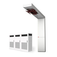
ABB HVC Installation Manual (128 pages)
450 kW E-Bus Charger
Brand:
ABB
| Category:
Battery Charger
| Size: 11.63 MB
Table of Contents
Table of Contents
4
1 Introduction
8
Preface
8
Intended Document Users
8
Signs
8
Safety Regulations
9
Owner Responsibilities
9
Tilting and Handling
10
Electric Hazards
11
Installation Safety
11
Environment and Disposal of Waste
12
Contact Information
13
2 Description of the Product
14
Overview of the System
14
Standard HVC 450 Kw E-Bus Charger with Pole
14
Standard HVC 450 Kw E-Bus Charger Without Pole
15
Power Cabinet
16
ACS Control Module
17
Junction Box
18
ABB Pole
18
Accessories
19
Foundation for Power Cabinet
19
Foundation for ABB Pole Construction
20
Communication Glass Fiber Cable
21
Electrical Components
21
Project Planning
23
3 Preparation
24
About Preparation
24
Permits
25
Power Connection
25
Construction Permit
25
Internet Access
25
Upgrade Grid
26
Location
26
Geometry of Infrastructure
27
Required Space for the Power Cabinet
27
Placement of Multiple Cabinets
28
Required Space for the ABB Pole
29
Pole Position in Relation to the Bus
29
Pole Position in Relation to the Drive Direction of the Bus
29
Pole Position in Sideways Direction of the Bus
30
Maximum Slope of the Road in Sideways Direction
32
Maximum Slope of the Road in Driving Direction
32
Electrical Engineering
33
Electrical Installation
33
Civil Installation
33
Lightning Protection
34
4 Construction
35
About Construction
35
Construct Foundation of the Power Cabinet
36
Options
36
Workflow with Pre-Fabricated Concrete Foundation
37
Workflow with Metal Frame Foundation
39
Workflow with Custom Foundation (Footprint)
40
Construct Foundation of the ABB Pole
41
Options
41
Pole Foundation Constructed on Site or Mounted on Concrete Floor
41
Workflow with Pre-Fabricated Concrete Foundation
42
Cabling
46
About Cabling
46
Charge System Configuration
47
AC Power Cable
47
Cables between the Power Cabinets and the ACS Control Module
47
Cables between the Power Cabinets
48
Cable Specification List
48
Internet Connection
50
5 Placement and Connection
51
About Placement and Connection
51
Route the Cables
52
Unpack Power Cabinet
53
Before Unpacking
53
Remove Packaging
54
Move Power Cabinet to Position
54
Move Cabinet with a Hoist
55
Move Cabinet with a Forklift Truck
56
Install Power Cabinet Onto the Foundation
57
Connect Power Cabinet to Foundation
57
Open the Door of the Power Cabinet
59
Move the Sliding Plate of the Guidance Plates of the Cabinet
60
Route Cables through Guidance Plates
60
Move Sliding Plates of the Guidance Plates of the Cabinet
61
Install Border Covers of the Power Cabinet
62
Install Border Covers of Metal Frame Foundation
62
Install Front Cover Plate on Foundation
63
Connect AC Power Cable and GND Wires Power Cabinets
64
Remove the Protection Covers
64
Connect the GND Wire of the AC Power Cable
65
Connect the AC Power Cable
66
Install the Protection Covers
67
Install Lightning Protection (Optional)
68
Connect the GND Wire to the ABB Pole
69
Connect the GND Wire between the Power Cabinets
69
Connect the DC Power Cables Power Cabinets
70
Remove the Protection Covers
71
Connect the DC Power Cables
71
Install the Protection Covers
72
Connect AC Utility Power, Interlock and CAN Cables Power Cabinet
72
Route the Cables to the Terminal Blocks
73
Connect the AC Utility Power Cable
73
Connect the Interlock Cable
74
Connect the CAN Cable
77
Connect the Communication Cable Power Cabinet
80
Route the Cable to the Terminal Blocks
80
Connect the Communication Fiber Cables
80
Close the Door of the Power Cabinet
81
Unpack the Charge Control Set
82
Before Unpacking
82
Remove Packaging
83
Move the ABB Pole to Position
83
Install Vertical Frame Onto the Foundation
84
Install Horizontal Frame Onto the Vertical Frame
86
Connect GND Wires to ABB Pole
89
Connect the GND Wire of the ACS GND
89
Connect the GND Wire from the Horizontal Frame
89
Connect the GND Wire from the Junction Box
90
Connect the GND Wire of the Power Cabinet
90
Install Lighting Protection
91
Connect Cables ACS Control Module
91
Gland Layout of the ACS Control Module
92
Open the Door of the ACS Control Module
92
Connect the DC+ Power In- and Output Cables
93
Connect the DC- Power In- and Output Cables in Junction Box
95
Connect the AC Utility Power Cable from Power Cabinet
97
Connect the Communication Cable from the Power Cabinet
97
Connect the Wifi Cable
99
Connect the RFID Cables
99
Connect the Other Cables to the ACS Control Module
101
Close the Door of the ACS Control Module
102
Install Masks Plate Work
103
Grouting of the Pole Construction
108
6 Commissioning
109
Commissioning Preparation
109
Customer Acceptance Form (CAF)
110
7 Service and Maintenance
111
About Service and Maintenance
111
Cleaning of the Cabinet
111
8 Technical Specification
112
Electrical Specification Complete System
112
Mechanical Data
112
Environment
113
Certifications
113
9 Appendix
114
A Dimensions Power Cabinet
115
B Dimensions ACS Control Module
117
C Dimensions Junction Box
118
D Dimensions ABB Pole
119
E Dimensions Concrete Foundation Power Cabinet
121
F Dimensions Metal Foundation Power Cabinet
123
G Dimensions Pre-Fabricated Concrete Foundation Pole
124
H Power Cabinet - Outline with Foundation
125
I Signal Connection Diagram
126
J Ground Overview of the System
127
Advertisement
Advertisement
Related Products
ABB HVC-PD
ABB HVC-R 100
ABB HVC-R 150
ABB HVC 100C
ABB HVC 150C
ABB HVC-R 100 V2
ABB HVC-R 150 V2
ABB HVC 150P
ABB HVC 300P
ABB HVC 450P
ABB Categories
Industrial Equipment
Controller
Measuring Instruments
Battery Charger
DC Drives
More ABB Manuals
Login
Sign In
OR
Sign in with Facebook
Sign in with Google
Upload manual
Upload from disk
Upload from URL