
Related Manuals for ABB HVC


Summary of Contents for ABB HVC
- Page 1 Attachment A — IN STA L L AT I ON G U ID E HVC 450 kW E-Bus Charger Installation Guide for NA products Version 1.2...
- Page 2 ABB cannot be held liable for errors in the translation. This document and parts thereof must not be reproduced or copied without written permission from ABB, and the contents there of must not be imparted to a third party nor used for any unauthorized purpose.
- Page 3 ACM adapted. 30-04-2018 First commercial release. 20-07-2018 Height specification HVC 150 adapted. Adapt instruction for GND connection in Power Cabinet. Removed UL Listing logo on page 112 and put 2202 after UL in the table in 8.4. 16-08-2018 Correct description Interlock connection within salve 1 HVC150S (Mantis PR10833).
-
Page 4: Table Of Contents
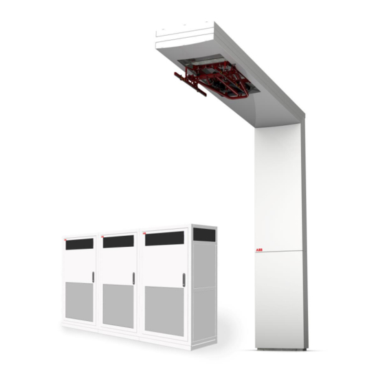
1.5. Environment and disposal of waste 1.6. Contact information Description of the product 2.1. Overview of the system 2.1.1. Standard HVC 450 kW E-Bus Charger with pole 2.1.2. Standard HVC 450 kW E-Bus Charger without pole 2.1.3. Power Cabinet 2.1.4. - Page 5 HVC 450 kW E-Bus Charger Installation Guide 4.2.1. Options 4.2.2. Workflow with pre-fabricated concrete foundation 4.2.3. Workflow with metal frame foundation 4.2.4. Workflow with custom foundation (footprint) 4.3. Construct foundation of the ABB Pole 4.3.1. Options 4.3.2. Pole foundation constructed on site or mounted on concrete floor 4.3.3.
- Page 6 HVC 450 kW E-Bus Charger Installation Guide 5.10. Close the door of the Power Cabinet 5.11. Unpack the Charge control set 5.11.1. Before unpacking 5.11.2. Remove packaging 5.12. Move the ABB pole to position 5.13. Install vertical frame onto the foundation 5.14.
- Page 7 Alternating Current. A computer network that interconnects computers systems within a limited area. ACS Control Module ABB Network Operating Centre; remotely checks the correct functioning of the charger. Automatic Control System. In this charger system the pantograph. OPP Charge Is a trade name of fast charging method for electric vehicles.
-
Page 8: Introduction
This guide describes the planning and physical installation of the HVC E-Bus Charger at its location for the North American (NA) region. The HVC 450 kW E-Bus Charger is a DC fast charger system for hybrid or electrical buses that are compatible with the OPP Charging standard . -
Page 9: Safety Regulations
HVC 450 kW E-Bus Charger Installation Guide WARNING Pinch Hazard Identifies a hazard that could result in injuries in which some body parts are pinched or crushed. WARNING Fall Hazard Identifies a hazard that could result in injury due unsafe work at height. -
Page 10: Tilting And Handling
ABB’s warranty policy. Neither ABB nor its affiliates shall be liable to the purchaser of this product or third parties for damages, losses, costs or expenses incurred by purchaser or third parties... -
Page 11: Electric Hazards
2. Do a voltage check and make sure that the electrical power is disconnected from the system. 3. Only ABB certified technicians are permitted to commission the HVC 450 kW E-Bus Charger. 4. When the system is in an open or dangerous condition, do not allow unqualified persons to go near it. -
Page 12: Environment And Disposal Of Waste
1.5. Environment and disposal of waste CAUTION Always observe the local rules and regulations with respect to processing (non-reusable) parts of the HVC 450 kW E-Bus Charger. Revision: 1.2 COMPANY CONFIDENTIAL Page 12 of 128 Date released: 16-08-2018... -
Page 13: Contact Information
HVC 450 kW E-Bus Charger Installation Guide 1.6. Contact information ABB in your country Please contact ABB in your country for sales, delivery and service information. ABB EV Infrastructure global ABB EV Infrastructure Address Delftweg 65 2289 BA Rijswijk The Netherlands... -
Page 14: Description Of The Product
Bus stop space for Opportunity Charging (OPP Charge) Electric hybrid and/or full electric Bus The HVC 450 kW E-Bus Charger consists out of multiple components and it may require additional parts depending on the project and location of installation which dictates whether these parts are needed. -
Page 15: Standard Hvc 450 Kw E-Bus Charger Without Pole
The cables between the ACS Control Module and pantograph is not part of the order. However, the length of the cable will depend on site survey (for pole) conducted by ABB. ABB has a standard cable list (see section Communication glass fiber cable on Page 21) to be used for these cables, if the site has special conditions apart from being exposed to sun;... -
Page 16: Power Cabinet
HVC 450 kW E-Bus Charger Installation Guide 2.1.3. Power Cabinet Outside view of the Power Cabinet Base cover 3G Antenna Air outlet Air inlets (also on the left and back side) Door Door handle / lock Inside view of the Power Cabinet... -
Page 17: Acs Control Module
HVC 450 kW E-Bus Charger Installation Guide 2.1.4. ACS Control Module Outside view of the ACS Control Module Door Locks WiFi coax connector In- and outputs for cables from Power Cabinet and to pantograph In- and outputs DC power cables... -
Page 18: Junction Box
HVC 450 kW E-Bus Charger Installation Guide 2.1.5. Junction Box Outside view Junction Box Cover In- and outputs DC power cables Output DC- OVP sensing cable 2.1.6. ABB Pole Outside view ABB Pole Door Emergency button (EMO) Charge state indicator light (beacon) -
Page 19: Accessories
Tension spring Collector head 2.2. Accessories The following parts can be ordered at the time of the initial order or afterwards. Contact ABB Sales department (see Contact information on Page 13 for contact details). 2.2.1. Foundation for Power Cabinet Pre-fabricated concrete foundation The pre-fabricated concrete foundation can be used to install the Power Cabinet on soil. -
Page 20: Foundation For Abb Pole Construction
The pre-fabricated concrete foundation can be used to install the ABB Pole construction on soil. Base plate Counter weights Pulse tube foundation The pulse tube foundation can be used to install the ABB Pole construction on soil. Revision: 1.2 COMPANY CONFIDENTIAL Page 20 of 128 Date released: 16-08-2018... -
Page 21: Communication Glass Fiber Cable
HVC 450 kW E-Bus Charger Installation Guide 2.2.3. Communication glass fiber cable The CAN and Ethernet communication between the Power Cabinet and Charge control set is done via a glass fiber cable. This glass fiber cable must be prefabricated and can be ordered separately. - Page 22 HVC 450 kW E-Bus Charger Installation Guide Amount Part number Description RFU 630-13101 RFID RFU63x (Sick) SSL-2J04-G10ME (part RFID Ethernet cable 10 m (male connector, M12, 4-pin, straight, 6030928) D-coded / male connector, RJ45, 8-pin, straight) (Sick) 2070427 RFID Power cable 10 m (female connector, M12, 17-pin, straight, A-coded) (Sick) Revision: 1.2...
-
Page 23: Project Planning
The different phases of the full project plan are shown in the figure below: A. Preparation The owner / site operator has ordered a HVC 450 kW E-Bus Charger. In this phase all preparation work must be done before the contractor can do the civil and electrical works. -
Page 24: Preparation
The contractor is responsible for all construction documentation of the site, among other things: drawings, calculations, certifications, licenses and test reports. The location of the HVC 450 kW E-Bus Charger must be chosen. See section Location on Page 26 and section Geometry of infrastructure on Page 27. -
Page 25: Permits
Make sure the plan includes the possibility for these delays. 3.2. Permits The installation of a HVC 450 kW E-Bus Charger will require a number of permits, depending on national and local laws. This section lists a number of points of attention. 3.2.1. Power connection The HVC 450 kW E-Bus Charger requires high current (480 V AC 576 A) connections. -
Page 26: Upgrade Grid
HVC 450 kW E-Bus Charger Installation Guide 3.3. Upgrade grid The HVC 450 kW E-Bus Charger can be connected directly to the electrical grid or to an existing customer low voltage power distribution cabinet. In both cases a 576 A, 480 V AC, 60 Hz, 3P+GND connection is required. -
Page 27: Geometry Of Infrastructure
3.5.1. Required space for the Power Cabinet A single HVC 150 (or HVC 150S) Power Cabinet requires a minimum space of 46.06 x 81.50 Inch (W x D) or 53.94 x 77.56 Inch (W x D). This space is calculated as follows: ... -
Page 28: Placement Of Multiple Cabinets
HVC 450 kW E-Bus Charger Installation Guide The HVC 150(S) has air inlets (A) on all sides and air outlet (B) on the front to control the temperature inside the cabinet. Do not install any objects near these air inlets and outlets (see also Caution above). -
Page 29: Required Space For The Abb Pole
HVC 450 kW E-Bus Charger Installation Guide 3.5.3. Required space for the ABB pole The ABB pole requires a space of 48.82 x 51.18 Inch. This space is calculated as follows: An ABB pole footprint of 40.95 x 11.81 Inch. -
Page 30: Pole Position In Sideways Direction Of The Bus
HVC 450 kW E-Bus Charger Installation Guide 3.6.2. Pole position in sideways direction of the bus The minimum distance is 35.43 Inch and the maximum 70.87 Inch between side of the pole and street curb. Be aware this is in case the road is flat and doesn’t have an angle in the sideway direction of the bus, else the minimum and maximum distance need to be re- calculated. - Page 31 The pole can be placed on the left side or on the right side (driver side) of the bus. This must be communicated with ABB before ordering the ABB pole. This will also be noted by ABB during the site survey for the placement of the pole. Contact ABB Sales department (see Contact information on Page 13 for contact details).
-
Page 32: Maximum Slope Of The Road In Sideways Direction
The road inclination should be known before the pole can be built. This must be communicated with ABB before ordering the ABB pole. This will also be noted by ABB during the site survey for the placement of the pole. Contact ABB Sales department (see Contact information on Page 13 for contact details). -
Page 33: Electrical Engineering
HVC 450 kW E-Bus Charger Installation Guide The installation can handle a road inclination smaller than 2.5° without any modification to the position of the pantograph. When the road inclination is between 2.5° and 5.0°, the position of the pantograph must be adjusted during production of the pole. The road inclination should not be greater than 5.0°. -
Page 34: Lightning Protection
HVC 450 kW E-Bus Charger Installation Guide Example of civil installation Foundations of Power Cabinet Foundation of ABB Pole Flexible conduit for DC power cables Flexible conduit for AC utility power, GND wire and data cables AC power cables (required individually for each Power Cabinet) -
Page 35: Construction
4. Construction 4.1. About construction The construction phase includes all work required to prepare the location and make it ready for the placement and connection of the HVC 450 kW E-Bus Charger. The construction phase can start when: All engineering work is done. -
Page 36: Construct Foundation Of The Power Cabinet
HVC 450 kW E-Bus Charger Installation Guide Transport Arrangement for the delivery of the HVC 450 kW E-Bus Charger with the ABB Delivery department. See Contact information on Page 13 for contact details. The delivery time is at least four months. -
Page 37: Workflow With Pre-Fabricated Concrete Foundation
HVC 450 kW E-Bus Charger Installation Guide 4.2.2. Workflow with pre-fabricated concrete foundation WARNING Make sure that personnel cannot be crushed or become trapped while moving the foundation. Be aware that the weight of the concrete foundation is about 2866 lb. - Page 38 HVC 450 kW E-Bus Charger Installation Guide NOTICE This extra cable length is required to connect the AC power cable with the connectors in the Power Cabinet without problems. 11. Place both cover plates on the appropriate place on the foundation.
-
Page 39: Workflow With Metal Frame Foundation
NOTICE The hole distance of 25.79 Inch on either side of the metal frame foundation is not equal to the hole distance (26.77 Inch) from the HVC 150(S) cabinet. See also the mechanical drawing in Appendix F Dimensions Metal Foundation Power Cabinet on page 123. -
Page 40: Workflow With Custom Foundation (Footprint)
HVC 450 kW E-Bus Charger Installation Guide 4.2.4. Workflow with custom foundation (footprint) Drill and tap holes in the floor at the indicated positions (A). The holes must be suitable for bolt size M16. Make rectangular holes on the indicated positions (B) and (C). For detail drawings bottom view of Power Cabinet see Appendix A Dimensions Power Cabinet. -
Page 41: Construct Foundation Of The Abb Pole
HVC 450 kW E-Bus Charger Installation Guide 4.3. Construct foundation of the ABB Pole 4.3.1. Options Use the correct foundation for the type of surface that the ABB Pole will be installed on: Soil (option 1, most common) Use a concrete foundation (pre-fabricated or poured concrete foundation on site) to get a firm fixation on soil. -
Page 42: Workflow With Pre-Fabricated Concrete Foundation
100 kPa, no soil compact actions has to be taken. If the concrete foundation will be installed on another ground type than sand (like rock, gravel, clay or peat), take contact with the ABB Sales department, see Contact information on Page 13 for contact details. - Page 43 (see Contact information on Page 13 for contact details). Installing the concrete base plate Preconditions: 4x WLL 3/5.0 tons lifting claws (are not delivered by ABB, use for example Starcon Universal Lifting Claws, art.no. 99.11590082B). WARNING Make sure that personnel cannot be crushed or become trapped while moving the foundation.
- Page 44 HVC 450 kW E-Bus Charger Installation Guide The base plate has holes for entering cables into the charging pole construction which are positioned aligned with the road. The base plate must be positioned in the right way to have the cable conduits facing towards the foundation of the Power Cabinet. The base plate can be installed 180 degrees to face the cable entries to the other side.
- Page 45 Installing the counter weights Preconditions: 2x WLL 1.5/2.5 tons lifting claws (are not delivered by ABB, use for example Starcon Universal Lifting Claws, art.no. 99.11590081B). With the concrete base plate in position the counter weights can be installed. These counter weights are needed to keep the charging pole construction up right during extreme weather conditions and to prevent the construction from tilting.
-
Page 46: Cabling
Cabinet and Charge Post. Mechanical lugs can be used at the discretion of the installer and will be separately provided. CAUTION ABB is not responsible for damage caused to the Charger system due to the use of mechanical lugs, and is not covered by the warranty. Revision: 1.2... -
Page 47: Charge System Configuration
1x Interlock cable, 4x communication cables; 8x glass fiber (4 fibers are required, 4 are for spare). The 8x glass fiber cable is a special cable that will be supplied by ABB. Revision: 1.2 COMPANY CONFIDENTIAL Page 47 of 128... -
Page 48: Cables Between The Power Cabinets
(= 350 MCM) (with a reinforced isolation > 5400 V DC) for a distance until 492.13 ft. 4.4.5. Cables between the Power Cabinets The following cables are not in the scope of supply of ABB. 1x GND cable; ... - Page 49 All cables must be must meet the UL and the RoHS compliance. Cables between ACS Control Module and Pantograph These cables normally integrated within the ABB pole, however, these cables needed if the charge system is ordered without ABB pole.
-
Page 50: Internet Connection
In most cases the integrated 3G modem is used for wireless internet access. A customer SIM card is not required. If there is no 3G signal available, a standard wired internet connection is required. For this option, contact ABB Sales department (see Contact information on Page 13 for contact details). -
Page 51: Placement And Connection
5. Placement and Connection 5.1. About placement and connection When all mechanical work is finished, the HVC 450 kW E-Bus Charger can be placed and connected. The planning steps for the placement and connection phase are shown in the figure below. -
Page 52: Route The Cables
HVC 450 kW E-Bus Charger Installation Guide Connect the GND wire to the ABB Pole on Page 89 and Connect cables ACS Control Module on Page 91. Install masks plate work on Page 103 and Grouting of the pole construction on Page 108. -
Page 53: Unpack Power Cabinet
HVC 450 kW E-Bus Charger Installation Guide For the DC power cables, make sure that a cable length of 39.37 Inch is available above the surface for internal routing in the cabinet. For the other cables, make sure that a cable length of 118.11 Inch is available above the surface for internal routing in the cabinet. -
Page 54: Remove Packaging
HVC 450 kW E-Bus Charger Installation Guide 5.3.2. Remove packaging Preconditions Tools: spanner (size 24). Remove the packaging material from the Power Cabinet. Remove the bag which contain the keys, cover caps and mounting material that are attached with tape on one of the lifting eyebolt at the top of the cabinet. -
Page 55: Move Cabinet With A Hoist
HVC 450 kW E-Bus Charger Installation Guide DANGER Make sure that the main switch of the power supply group for the product is set to the OFF position. Do a voltage check to make sure that the electrical power is disconnected from the system. -
Page 56: Move Cabinet With A Forklift Truck
HVC 450 kW E-Bus Charger Installation Guide Insert the bolts (A) or (B) into the holes at the opposite corners of the cabinet, if not placed upon delivery. Tighten the bolts. Connect the hoisting equipment (C). CAUTION Keep the hoisting angle below 60⁰. -
Page 57: Install Power Cabinet Onto The Foundation
HVC 450 kW E-Bus Charger Installation Guide 5.5. Install Power Cabinet onto the foundation 5.5.1. Connect Power Cabinet to foundation Preconditions: Tools: spanner (size 24). Cover caps (4x) that were removed from the Power Cabinet (bag with parts). - Page 58 HVC 450 kW E-Bus Charger Installation Guide Placement on metal frame foundation Foundation Power Cabinet Cables Tapped holes Carefully lower the Power Cabinet (B) onto the foundation (A). Make sure that you do not trap the cables (C). Make sure that the cabinet is aligned with the tapped holes (D).
-
Page 59: Open The Door Of The Power Cabinet
HVC 450 kW E-Bus Charger Installation Guide Tighten the bolt with a tightening torque of 147.51 ft-lb. Remove the swivel eye bolts or lifting loops (A). Place the cover caps (B) in the holes (4x). 5.5.2. Open the door of the Power Cabinet Preconditions: ... -
Page 60: Move The Sliding Plate Of The Guidance Plates Of The Cabinet
HVC 450 kW E-Bus Charger Installation Guide 5.5.3. Move the sliding plate of the guidance plates of the cabinet Preconditions: Tools: spanner (size 13). Loosen the bolts (A). Move the sliding plate (B) of the 2 guidance plates. 5.5.4. Route cables through guidance plates Route the cables (A) through the right guidance plates (B). -
Page 61: Move Sliding Plates Of The Guidance Plates Of The Cabinet
HVC 450 kW E-Bus Charger Installation Guide NOTICE A length of 118.11 Inch is required, because the connection of the cables with the connectors in the Power Cabinet is at the middle of the cabinet. 5.5.5. Move sliding plates of the guidance plates of the cabinet Preconditions: ... -
Page 62: Install Border Covers Of The Power Cabinet
HVC 450 kW E-Bus Charger Installation Guide 5.5.6. Install border covers of the Power Cabinet Preconditions: Tools: spanner (size 8 and 10). M6 nuts and washers (4x) that were removed from the Power Cabinet (bag with parts). ... -
Page 63: Install Front Cover Plate On Foundation
HVC 450 kW E-Bus Charger Installation Guide Put the front border cover (A) against the bottom front of the Power Cabinet. Put the rear border cover (B) against the rear front of the Power Cabinet. Insert the M5 bolts (C) into the holes (8x). -
Page 64: Connect Ac Power Cable And Gnd Wires Power Cabinets
HVC 450 kW E-Bus Charger Installation Guide Insert the M12 bolts (C) into the holes (4x). Tighten the bolts. 5.6. Connect AC power cable and GND wires Power Cabinets 5.6.1. Remove the protection covers Preconditions: Tools: cross-head screwdriver Remove the protection plate (A) by loosening the screws (B). -
Page 65: Connect The Gnd Wire Of The Ac Power Cable
HVC 450 kW E-Bus Charger Installation Guide 5.6.2. Connect the GND wire of the AC power cable Preconditions: Tools: wire cutter, wire stripper pliers, wire-end ring, spanner (size 19), torque wrench (size 19). DANGER Make sure that the main switch of the power supply group for the product is set to the OFF position. -
Page 66: Connect The Ac Power Cable
HVC 450 kW E-Bus Charger Installation Guide 5.6.3. Connect the AC power cable Preconditions: Tools: wire cutter, wire stripper pliers, spanner (size 19), torque wrench (size 19). DANGER Make sure that the main switch of the power supply group for the product is set to the OFF position. -
Page 67: Install The Protection Covers
HVC 450 kW E-Bus Charger Installation Guide 5.6.4. Install the protection covers Preconditions: Tools: cross-head screwdriver Take the 3 protection covers that was removed in Remove the protection covers on Page Place the protection covers (D) back on the connector blocks (C). -
Page 68: Install Lightning Protection (Optional)
Leave the main switch switched off. The Power Cabinet is not ready for use yet. If there is no appointment for commissioning yet, contact the ABB Delivery department to make an appointment for commissioning. See Contact information on Page 13 for contact details. -
Page 69: Connect The Gnd Wire To The Abb Pole
HVC 450 kW E-Bus Charger Installation Guide 5.6.6. Connect the GND wire to the ABB Pole NOTICE The GND wire to the ABB Pole is only connected within the HVC 150 Power Cabinet, see for more details section Cabling on Page 46. Preconditions: ... -
Page 70: Connect The Dc Power Cables Power Cabinets
HVC 450 kW E-Bus Charger Installation Guide Both GND wire connection must be made between the HVC 150 and the first HVC 150S and between both HVC 150S, see also section Cabling on Page 46: Cut the GND wire of the power cable to the correct length to reach the GND rail. Do not make the wire routing too tight, or too loose. -
Page 71: Remove The Protection Covers
HVC 450 kW E-Bus Charger Installation Guide 5.7.1. Remove the protection covers Remove the 2 protection covers (B) from the connector blocks (A). Put the protection covers in a safe location as it will be installed again later on. 5.7.2. Connect the DC power cables Cut the wires of the DC power cable to the correct lengths to reach the connectors. -
Page 72: Install The Protection Covers
HVC 450 kW E-Bus Charger Installation Guide DC+ (marked by red heat-shrink), DC-. Tighten the nuts (C) with a tightening torque of 22.13 ft-lb. 5.7.3. Install the protection covers Take the 2 protection covers that was removed in Remove the protection covers on Page Place the protection covers (B) back on the connector blocks (A). -
Page 73: Route The Cables To The Terminal Blocks
5.8.2. Connect the AC utility power cable NOTICE The AC utility power cable for the ACS Control Module is only connected within the HVC 150 Power Cabinet, see for more details section Cabling on Page 46. Revision: 1.2 COMPANY CONFIDENTIAL... -
Page 74: Connect The Interlock Cable
X341-4 Blue Tighten the connector screws. 5.8.3. Connect the Interlock cable Interlock cable connection in the slave 2 HVC 150S: Terminal block Interlock cable from/to slave 1 HVC 150S Move the cable towards the terminal block (A). Strip 0.43 Inch of the insulation from the ends of the wires. - Page 75 HVC 450 kW E-Bus Charger Installation Guide Interlock cable connection in slave 1 HVC 150S: Terminal block Interlock cable from/to slave 2 HVC 150S Interlock cable from/to master HVC 150 Move the cables towards the terminal block (A). Strip 0.43 Inch of the insulation from the ends of the wires.
- Page 76 HVC 450 kW E-Bus Charger Installation Guide Interlock cable connection in master HVC 150: Terminal block Interlock cable from/to slave 1 HVC 150S Interlock cable from/to ACS Control Module (ACM) Move the cables towards the terminal block (A). Strip 0.43 Inch of the insulation from the ends of the wires.
-
Page 77: Connect The Can Cable
HVC 450 kW E-Bus Charger Installation Guide 5.8.4. Connect the CAN cable CAN cable connection in slave 2 HVC 150S: Terminal block CAN cable to slave 1 HVC 150S Move the cable towards the terminal block (A). Strip 0.43 Inch of the insulation from the ends of the wires. - Page 78 X286-2 White CAN GND (to master HVC 150) X286-3 or Shield Can In Shield CAN H Out (from slave 2 HVC 150S) X286-10 Brown CAN L Out (from slave 2 HVC 150S) X286-11 White CAN GND (from slave 2 HVC 150S)
- Page 79 HVC 450 kW E-Bus Charger Installation Guide CAN cable connection in master HVC 150: Terminal block CAN cable from slave 1 HVC 150S Move the cable towards the terminal block (A). Strip 0.43 Inch of the insulation from the ends of the wires.
-
Page 80: Connect The Communication Cable Power Cabinet
5.9.1. Route the cable to the terminal blocks Preferred cable route Route the communication fiber cable to module D1 (B) and D2 (A). Refer to the figure for the preferred cable route inside the cabinet (only within the HVC 150). 5.9.2. Connect the communication fiber cables Preconditions: ... -
Page 81: Close The Door Of The Power Cabinet
HVC 450 kW E-Bus Charger Installation Guide Remove the protection covers from the optical connectors. Connect the two Ethernet fiber cables (C) onto the module D2 (A): Rx with Td D2; Tx with Rd D2. Connect the two CAN bus fiber cables (D) onto module D1 (B): ... -
Page 82: Unpack The Charge Control Set
HVC 450 kW E-Bus Charger Installation Guide 5.11. Unpack the Charge control set 5.11.1. Before unpacking The Charge control set will be delivered in four packages: 1. Vertical frame including the ACS Control Module. 2. Horizontal frame including the pantograph, WiFi communication unit and cables. -
Page 83: Remove Packaging
HVC 450 kW E-Bus Charger Installation Guide Check the delivery goods and boxes for damages. Check that all cable connections on the pantograph and Wifi communication unit are tight. WARNING Make sure that the painted seal on the pantograph electrical connectors are not damaged. Is this not the case, contact ABB Delivery department (see Contact information on Page 13 for contact details). -
Page 84: Install Vertical Frame Onto The Foundation
HVC 450 kW E-Bus Charger Installation Guide Move the vertical frame to the foundation. 5.13. Install vertical frame onto the foundation Preconditions: Tools: spanner (size 36), torque wrench (size 36) DANGER Make sure that the main switch of the power supply group for the product is set to the OFF position. - Page 85 HVC 450 kW E-Bus Charger Installation Guide Foundation Conduit with cables Vertical frame Opening for cables ACS Control Module Bolts (16x) Junction Box It is possible to choose to lubricate the bolts first or not with copper fat. NOTICE There are a number of reasons for using copper fat: ...
-
Page 86: Install Horizontal Frame Onto The Vertical Frame
Be aware that the correct height to the bottom side of the foot print of the vertical frame relative to the ground level of the top of road (= charging position of the bus) must be calculated by ABB. Contact ABB Sales department (see Contact information on Page 13 for contact details). - Page 87 HVC 450 kW E-Bus Charger Installation Guide Vertical frame Horizontal frame Lift the horizontal frame up to the connection point on the vertical frame. Carefully position the horizontal frame before the connection point on the vertical frame. Make sure that the horizontal frame is aligned with the tapped holes.
- Page 88 HVC 450 kW E-Bus Charger Installation Guide Second make the M16 bolt + washer / washer + nut connection. Use 10 pieces bolts of M16 x 50 Class 8.8 for this connection. A torque of 169.64 ft-lb has to be applied.
-
Page 89: Connect Gnd Wires To Abb Pole
HVC 450 kW E-Bus Charger Installation Guide 5.15. Connect GND wires to ABB Pole Preconditions: Tools: wire cutter, wire stripper pliers, wire-end ring, spanner (size 13) DANGER Make sure that the main switch of the power supply group for the product is set to the OFF position. -
Page 90: Connect The Gnd Wire From The Junction Box
HVC 450 kW E-Bus Charger Installation Guide Cut the GND wire to the correct length to reach the GND rail. Do not make the wire routing too tight, or too loose. Strip 0.79 Inch of the insulation from the end of the wire. -
Page 91: Install Lighting Protection
HVC 450 kW E-Bus Charger Installation Guide Strip 0.79 Inch of the insulation from the end of the wire. Attach a wire end ring (A) to the end of the GND wire (B). Remove the M8 bolt and washers from the GND rail. -
Page 92: Gland Layout Of The Acs Control Module
HVC 450 kW E-Bus Charger Installation Guide 5.16.1. Gland layout of the ACS Control Module Gland # Gland type Cable M16x1.5 AC utility power M16x1.5 Pantograph heater M16x1.5 Interlock M16x1.5 Pantograph CP/PE M25x1.5 RFID Ethernet M16x1.5 EMO switch M16x1.5 Beacon M16x1.5... -
Page 93: Connect The Dc+ Power In- And Output Cables
HVC 450 kW E-Bus Charger Installation Guide Unlock the locks (B). Open the door (A). 5.16.3. Connect the DC+ power in- and output cables Preconditions: Tools: wire cutter, wire stripper pliers, wire-end rings (Cembre A48-M12 cable lug, when using 500 MCM cables) (6x), spanner (size13 and 18), torque wrench (size 13 and 18). - Page 94 HVC 450 kW E-Bus Charger Installation Guide Loosen and remove the cable gland’s (#14 - #18 and #20) nuts, including the cover caps inside the gland, for the DC+ power cables. Slide the cable gland’s nuts over the DC power cables.
-
Page 95: Connect The Dc- Power In- And Output Cables In Junction Box
HVC 450 kW E-Bus Charger Installation Guide 14. Place the protection cover back on the DC contactors. 15. Hand tighten the screws of the protection cover. 16. Tighten the cable gland’s nut to secure the DC power cables. 5.16.4. Connect the DC- power in- and output cables in Junction Box Preconditions: ... - Page 96 HVC 450 kW E-Bus Charger Installation Guide Attach cable lug (C) at the end of the wires (D). Remove the M12 bolts, washers and nuts from the bus-bar (G). 10. Fit the bolt (E) with flat washer (F) and the wire (D) (6x).
-
Page 97: Connect The Ac Utility Power Cable From Power Cabinet
HVC 450 kW E-Bus Charger Installation Guide 5.16.5. Connect the AC utility power cable from Power Cabinet Preconditions: Tools: wire cutter, wire stripper pliers, screwdriver, ferrules, crimp pliers. Loosen and remove the cable gland’s (#1) nut for the AC utility power cable. - Page 98 HVC 450 kW E-Bus Charger Installation Guide Slide the cable gland’s nut (A) over the metal finish tulle (C) of the communication glass fiber cable. Slide the cable gland’s rubber seal (B) over the metal finish tulle (C) of the communication glass fiber cable.
-
Page 99: Connect The Wifi Cable
HVC 450 kW E-Bus Charger Installation Guide NOTICE Four fiber cables are not connected. Those fiber cables are meant for spare. 10. Bind the cables together and secure the loops loosely with a piece of tak-ty or ty-rap. CAUTION Make the loop bend radius of the fiber cables not smaller than 2.52 Inch, otherwise the core of the fiber cable may break. - Page 100 HVC 450 kW E-Bus Charger Installation Guide Route the RFID Ethernet cable through gland #5 to module U10 (A). Insert the RJ45 connector (B) of the Ethernet cable into the Ethernet port X2 of module U10 (A) Tighten the nut of the gland to secure the RFID Ethernet cable.
-
Page 101: Connect The Other Cables To The Acs Control Module
HVC 450 kW E-Bus Charger Installation Guide 5.16.9. Connect the other cables to the ACS Control Module Preconditions: Tools: wire cutter, wire stripper pliers, screwdriver, ferrules, crimp pliers. Overview of the terminal block Pantograph heater cable EMO cable Interlock cable... -
Page 102: Close The Door Of The Acs Control Module
HVC 450 kW E-Bus Charger Installation Guide Wire 2 ACS Control cable Wire 1 ACS +24V Wire 2 ACS -24V GND (green/yellow) Wire 3 ACS Extend/Retract Out Wire 4 ACS Magn Reed In Wire 5 ACS Supply/Retract Out Wire 6... -
Page 103: Install Masks Plate Work
HVC 450 kW E-Bus Charger Installation Guide 5.18. Install masks plate work Preconditions: The masks plates are unloaded from the delivery truck. Packing foil are removed from the plate work. The work must be carried out by at least two persons. - Page 104 HVC 450 kW E-Bus Charger Installation Guide Mount on the predrilled holes on both sides of the vertical frame (A) one socket bolt M6x16 including with washer (B). Hang the backside below cover (A) on the two bolts (B). Revision: 1.2...
- Page 105 HVC 450 kW E-Bus Charger Installation Guide Mount the rest of the fasteners (A) in the following order: lock washer M6, flat washer M6 and bolt M6x16 (6x). Repeat step 4, 5 and 6 for the backside up cover (A) and front side up cover (B).
- Page 106 HVC 450 kW E-Bus Charger Installation Guide Mount the cover door (A) on the four hinges mounted on the left side of the vertical frame (B). Place the hinge-pins (C) into the hinges to secure the door. Check if the door can be closed and locked.
- Page 107 HVC 450 kW E-Bus Charger Installation Guide 11. Mount cover (A) under the horizontal frame. Pull them as far as possible to the front. 12. Repeat step 4, 5 and 6 for the top back under cover (A) and the top front under cover (B).
-
Page 108: Grouting Of The Pole Construction
HVC 450 kW E-Bus Charger Installation Guide 5.19. Grouting of the pole construction Preconditions: All construction work on the pole is completed. The Side Acceptance test (SAT) is completed. Tools: non-shrink pour mortar (recommended Maxit EXM721), mixing tool, bucket or caster. -
Page 109: Commissioning
The planning steps for the commissioning phase are shown in the figure below. Commissioning The commissioning of the HVC 450 kW E-Bus Charger need to be performed by a service engineer from the ABB Delivery department and/or a certified local ABB service engineer. -
Page 110: Customer Acceptance Form (Caf)
SAT checklist, list of remaining items. After the CAF has been signed, the customer support will be handled by the ABB Service department. If there are any remaining items, they can be noted on the CAF document, together with the agreed solution and the expected date of completion. -
Page 111: Service And Maintenance
7.2. Cleaning of the cabinet The Power Cabinet and ABB Pole is powder coated. This coating must be kept in good condition. Clean the Power Cabinet and ABB Pole three times a year in the following way: ... -
Page 112: Technical Specification
HVC 450 kW E-Bus Charger Installation Guide 8. Technical Specification 8.1. Electrical specification complete system Input Supply voltage 3-phase, 480 V AC: GND, L1, L2, L3 Input voltage range 480 V AC ± 10% Input frequency range 60 Hz ± 1%... -
Page 113: Environment
89.5 mph (14 Bft) Storage conditions Indoors, dry CAUTION Warranty Warranty will be considered void when the HVC 450 kW E-Bus Charger is damaged while badly stored at the customer's location. 8.4. Certifications Certifications for complete system UL 2202 HVC 150: Certificate No. TU 72180445... -
Page 114: Appendix
HVC 450 kW E-Bus Charger Installation Guide 9. Appendix Dimensions Power Cabinet Dimensions ACS Control Module Dimensions Junction Box Dimensions ABB Pole Dimensions Concrete Foundation Power Cabinet Dimensions Metal Foundation Power Cabinet Dimensions pre-fabricated Concrete Foundation Pole Power Cabinet – Outline with Foundation... -
Page 115: A Dimensions Power Cabinet
HVC 450 kW E-Bus Charger Installation Guide A. Dimensions Power Cabinet All sizes in mm 1 mm = 0.039 Inch Revision: 1.2 COMPANY CONFIDENTIAL Page 115 of 128 Date released: 16-08-2018... - Page 116 HVC 450 kW E-Bus Charger Installation Guide All sizes in mm 1 mm = 0.039 Inch Revision: 1.2 COMPANY CONFIDENTIAL Page 116 of 128 Date released: 16-08-2018...
-
Page 117: B Dimensions Acs Control Module
HVC 450 kW E-Bus Charger Installation Guide B. Dimensions ACS Control Module All sizes in mm 1 mm = 0.039 Inch Revision: 1.2 COMPANY CONFIDENTIAL Page 117 of 128 Date released: 16-08-2018... -
Page 118: C Dimensions Junction Box
HVC 450 kW E-Bus Charger Installation Guide C. Dimensions Junction Box All sizes in mm 1 mm = 0.039 Inch Revision: 1.2 COMPANY CONFIDENTIAL Page 118 of 128 Date released: 16-08-2018... -
Page 119: D Dimensions Abb Pole
HVC 450 kW E-Bus Charger Installation Guide D. Dimensions ABB Pole All sizes in mm 1 mm = 0.039 Inch Revision: 1.2 COMPANY CONFIDENTIAL Page 119 of 128 Date released: 16-08-2018... - Page 120 HVC 450 kW E-Bus Charger Installation Guide All sizes in mm 1 mm = 0.039 Inch Revision: 1.2 COMPANY CONFIDENTIAL Page 120 of 128 Date released: 16-08-2018...
-
Page 121: E Dimensions Concrete Foundation Power Cabinet
HVC 450 kW E-Bus Charger Installation Guide E. Dimensions Concrete Foundation Power Cabinet All sizes in mm 1 mm = 0.039 Inch Revision: 1.2 COMPANY CONFIDENTIAL Page 121 of 128 Date released: 16-08-2018... - Page 122 HVC 450 kW E-Bus Charger Installation Guide All sizes in mm 1 mm = 0.039 Inch Revision: 1.2 COMPANY CONFIDENTIAL Page 122 of 128 Date released: 16-08-2018...
-
Page 123: F Dimensions Metal Foundation Power Cabinet
HVC 450 kW E-Bus Charger Installation Guide F. Dimensions Metal Foundation Power Cabinet All sizes in mm 1 mm = 0.039 Inch Revision: 1.2 COMPANY CONFIDENTIAL Page 123 of 128 Date released: 16-08-2018... -
Page 124: G Dimensions Pre-Fabricated Concrete Foundation Pole
HVC 450 kW E-Bus Charger Installation Guide G. Dimensions pre-fabricated Concrete Foundation Pole All sizes in mm 1 mm = 0.039 Inch Revision: 1.2 COMPANY CONFIDENTIAL Page 124 of 128 Date released: 16-08-2018... -
Page 125: H Power Cabinet - Outline With Foundation
HVC 450 kW E-Bus Charger Installation Guide H. Power Cabinet – Outline with Foundation Revision: 1.2 COMPANY CONFIDENTIAL Page 125 of 128 Date released: 16-08-2018... -
Page 126: I Signal Connection Diagram
HVC 450 kW E-Bus Charger Installation Guide I. Signal connection diagram Revision: 1.2 COMPANY CONFIDENTIAL Page 126 of 128 Date released: 16-08-2018... -
Page 127: J Ground Overview Of The System
HVC 450 kW E-Bus Charger Installation Guide J. Ground overview of the system Revision: 1.2 COMPANY CONFIDENTIAL Page 127 of 128 Date released: 16-08-2018... - Page 128 HVC 450 kW E-Bus Charger Installation Guide NOTES Revision: 1.2 COMPANY CONFIDENTIAL Page 128 of 128 Date released: 16-08-2018...