Sign In
Upload
Manuals
Brands
ABB Manuals
Battery Charger
HVC-PD
ABB HVC-PD Manuals
Manuals and User Guides for ABB HVC-PD. We have
2
ABB HVC-PD manuals available for free PDF download: Installation Manual
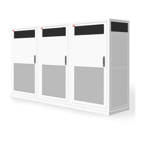
ABB HVC-PD Installation Manual (146 pages)
Brand:
ABB
| Category:
Battery Charger
| Size: 25.78 MB
Table of Contents
Table of Contents
4
Introduction
9
Preface
9
Intended Document Users
9
Signs
9
Safety Regulations
10
Owner Responsibilities
10
Tilting and Handling
11
Electric Hazards
12
Installation Safety
12
Environment and Disposal of Waste
13
Cyber Security Disclaimer
13
Contact Information
14
Description of the Product
15
Overview of the System
15
Standard HVC-PD 150 Kw E-Bus Charger System
15
Standard HVC-PD 300 Kw E-Bus Charger System
16
Standard HVC-PD 450 Kw E-Bus Charger System
16
Power Cabinet
17
ACS Control Module
18
Junction Box
19
Charge Pole
19
Accessories
20
Foundation for Power Cabinet
20
Foundation for Charge Pole Construction
21
Communication Glass Fiber Cable
22
RFID Unit
23
Project Planning
24
Preparation
25
About Preparation
25
Permits
26
Power Connection
26
Construction Permit
26
Internet Access
26
Upgrade Grid
27
Location
27
Geometry of Infrastructure
28
Required Space for the Power Cabinet
28
Placement of Multiple Cabinets
29
Required Space for the Charge Pole
30
Pole Position in Relation to the Bus
31
Pole Position in Relation to the Drive Direction of the Bus
32
Pole Position in Sideways Direction of the Bus
32
Maximum Slope of the Road in X-Axis
34
Maximum Slope of the Road in Z-Axis
35
Electrical Engineering
36
Electrical Installation
36
Civil Installation
36
Lightning Protection
37
Construction
38
About Construction
38
Construct Foundation of the Power Cabinet
39
Options
39
Workflow with Concrete Foundation
40
Workflow with Metal Frame Foundation
42
Hpc175-Hvc150 Met Found Kin 8In - Nam (2Ceb489802R0001)
42
Workflow Mounting Power Cabinet Direct on a Floor (Footprint)
43
Construct Foundation of the Charge Pole (for Reference Only)
44
Options
44
Workflow with Pre-Fabricated Concrete Foundation (for Reference Only)
44
Cabling
49
Charge System Configuration
49
AC Power Cable
51
Cables between the Power Cabinets and the ACS Control Module
51
Cables between the Power Cabinets
51
Cable Specification List
52
Internet Connection
53
Placement and Connection
54
About Placement and Connection
54
Route the Cables
55
Unpack Power Cabinet
55
Before Unpacking
55
Remove Packaging
57
Move Power Cabinet to Position
57
Move Cabinet with a Hoist
58
Move Cabinet with a Forklift Truck
59
Install Power Cabinet Onto the Foundation
60
Connect Power Cabinet to Foundation
60
Open the Door of the Power Cabinet
62
Move the Sliding Plate of the Guidance Plates of the Cabinet
63
Route Cables through Guidance Plates
63
Move Sliding Plates of the Guidance Plates of the Cabinet
64
Install Border Covers of the Power Cabinet
65
Install Border Covers of Metal Frame Foundation
65
Connect AC Power Cable and GND Wires Power Cabinets
66
Remove the Protection Covers
66
Connect the GND Wire of the AC Power Cable
67
Connect the AC Power Cable
68
Install the Protection Covers
70
Install Lightning Protection (Optional)
71
Connect the GND Wire to the Charge Pole
72
Connect the GND Wire between the Power Cabinets
73
Connect the DC Power Cables Power Cabinets
73
Connect the DC Power Cables
74
Install the Protection Cover
75
Connect AC Utility Power, Interlock and CAN Cables Power Cabinet
75
Route the Cables to the Terminal Blocks
75
Connect the AC Utility Power Cable
76
Connect the Interlock Cable for the HVC 150 Kw System
77
Upgrade the Interlock Connection to the HVC 300 Kw System
78
Upgrade the Interlock Connection to the HVC 450 Kw System
80
Connect the CAN Cable
82
Connect the Communication Cable Power Cabinet
85
Route the Cable to the Terminal Blocks
85
Connect the Communication Fiber Cables
85
Close the Door of the Power Cabinet
86
Unpack the Charge Pole
87
Before Unpacking
87
Remove Packaging
88
Move the Charge Pole to Position
88
Install Charge Pole Onto the Foundation
90
Install Mast Boom Onto Column
92
Pantograph Adjustment
97
Instruction for Pantograph Adjustment and Alignment
97
Pantograph Setting Range Adjustment
100
Pantograph Z-Axis Angle Adjustment
102
Pantograph X-Axis Angel Adjustment
103
Installation of the Cables Inside Charge Post
103
Open the Door and Remove Cover Plate
103
Connect GND Wires of the Power Cabinet
105
Install Lightning Protection
105
Gland Layout of the ACS Control Module
106
Open the Door of the ACS Control Module
107
Connect the DC+ Power Input Cables
107
Connect the DC- Power Input Cables in Junction Box
109
Connect the AC Utility Power Cable from Power Cabinet
111
Connect the Communication Cable from the Power Cabinet
112
Connect the Wifi Cable
112
Connect the RFID Cables
113
Connect the Interlock Cable from the Power Cabinet
114
Connect the Other Cables to the ACS Control Module
115
Close the Door of the ACS Control Module
118
Place Back Cover Plate and Close Door of the Charge Pole
118
Install Cover Plates
119
Grouting of the Pole Construction
120
Commissioning
121
Commissioning Preparation
121
Customer Acceptance Form (CAF)
122
Service and Maintenance
123
About Service and Maintenance
123
Cleaning of the Cabinet
123
Technical Specification
125
Electrical Specification Complete 150 Kw System
125
Electrical Specification Complete 300 Kw System
125
Electrical Specification Complete 450 Kw System
126
Mechanical Data
126
Environment
127
Certifications
127
Appendix
128
Dimensions Powe
129
Dimensions ACS Control Module
131
Dimensions Junction Box
132
Dimensions Charge Pole
133
Clearance and Vertical Working Range of the Pantograph
135
Dimensions Concrete Foundation Power Cabinet
136
Dimensions Metal Foundation Power Cabinet
138
Dimensions Concrete Foundation Pole
140
Power Cabinet - Outline with Foundation
141
Signal
142
Ground Overview of the System
145
Advertisement
ABB HVC-PD Installation Manual (139 pages)
Brand:
ABB
| Category:
Battery Charger
| Size: 13.38 MB
Table of Contents
Table of Contents
4
Introduction
9
Preface
9
Intended Document Users
9
Signs
9
Safety Regulations
10
Owner Responsibilities
10
Tilting and Handling
11
Electric Hazards
12
Installation Safety
12
Environment and Disposal of Waste
13
Contact Information
14
Description of the Product
15
Overview of the System
15
Standard HVC-PD 150 Kw E-Bus Charger System
15
Standard HVC-PD 300 Kw E-Bus Charger System
16
Standard HVC-PD 450 Kw E-Bus Charger System
16
Power Cabinet
17
ACS Control Module
18
Junction Box
19
Charge Pole
19
Accessories
20
Foundation for Power Cabinet
20
Foundation for Charge Pole Construction
21
Communication Glass Fiber Cable
22
RFID Unit
23
Project Planning
24
Preparation
25
About Preparation
25
Permits
26
Power Connection
26
Construction Permit
26
Internet Access
26
Upgrade Grid
27
Location
27
Geometry of Infrastructure
28
Required Space for the Power Cabinet
28
Placement of Multiple Cabinets
29
Required Space for the Charge Pole
30
Pole Position in Relation to the Bus
31
Pole Position in Relation to the Drive Direction of the Bus
31
Pole Position in Sideways Direction of the Bus
32
Maximum Slope of the Road in Sideways Direction
34
Maximum Slope of the Road in Driving Direction
34
Electrical Engineering
35
Electrical Installation
35
Civil Installation
35
Lightning Protection
36
Construction
37
About Construction
37
Construct Foundation of the Power Cabinet
38
Options
38
Workflow with Concrete Foundation
39
Workflow with Metal Frame Foundation
41
Workflow Mounting Power Cabinet Direct on a Floor (Footprint)
42
Construct Foundation of the Charge Pole
43
Options
43
Workflow with Pre-Fabricated Concrete Foundation
43
Cabling
48
About Cabling
48
Charge System Configurations
49
AC Power Cable
50
Cables between the Power Cabinets and the ACS Control Module
50
Cables between the Power Cabinets
51
Cable Specification List
51
Internet Connection
52
Placement and Connection
53
About Placement and Connection
53
Route the Cables
54
Unpack Power Cabinet
55
Before Unpacking
55
Remove Packaging
56
Move Power Cabinet to Position
56
Move Cabinet with a Hoist
57
Move Cabinet with a Forklift Truck
58
Install Power Cabinet Onto the Foundation
59
Connect Power Cabinet to Foundation
59
Open the Door of the Power Cabinet
61
Move the Sliding Plate of the Guidance Plates of the Cabinet
62
Route Cables through Guidance Plates
62
Move Sliding Plates of the Guidance Plates of the Cabinet
63
Install Border Covers of the Power Cabinet
64
Install Border Covers of Metal Frame Foundation
64
Install Front Cover Plate on Foundation
65
Connect AC Power Cable and PE Wires Power Cabinets
66
Remove the Protection Covers
66
Connect the PE Wire of the AC Power Cable
67
Connect the AC Power Cable
68
Install the Protection Covers
69
Install Lightning Protection (Optional)
70
Connect the PE Wire to the Charge Pole
71
Connect the PE Wire between the Power Cabinets
72
Connect the DC Power Cables Power Cabinets
72
Remove the Protection Cover
73
Connect the DC Power Cables
73
Install the Protection Cover
74
Connect AC Utility Power, Interlock and CAN Cables Power Cabinet
74
Route the Cables to the Terminal Blocks
74
Connect the AC Utility Power Cable
75
Connect the Interlock Cable for the HVC 150 Kw System
76
Upgrade the Interlock Connection to the HVC 300 Kw System
77
Upgrade the Interlock Connection to the HVC 450 Kw System
79
Connect the CAN Cable
81
Connect the Communication Cable Power Cabinet
84
Route the Cable to the Terminal Blocks
84
Connect the Communication Fiber Cables
84
Close the Door of the Power Cabinet
85
Unpack the Charge Pole Components
86
Before Unpacking
86
Remove Packaging
87
Move the Charge Pole to Position
87
Install Vertical Frame Onto the Foundation
88
Install Horizontal Frame Onto the Vertical Frame
91
Connect PE Wires to Charge Pole
93
Connect the PE Wire of the ACS PE
94
Connect the PE Wire from the Horizontal Frame
94
Connect the PE Wire from the Junction Box
95
Connect the PE Wire of the Power Cabinet
95
Install Lighting Protection
96
Connect Cables ACS Control Module
97
Gland Layout of the ACS Control Module
97
Open the Door of the ACS Control Module
98
Connect the DC+ Power In- and Output Cables
98
Connect the DC- Power In- and Output Cables in Junction Box
100
Connect the AC Utility Power Cable from Power Cabinet
102
Connect the Communication Cable from the Power Cabinet
103
Connect the Wifi Cable
104
Connect the RFID Cables
104
Connect the Other Cables to the ACS Control Module
106
Close the Door of the ACS Control Module
108
Install Masks Plate Work
109
Grouting of the Pole Construction
115
Commissioning
116
Commissioning Preparation
116
Customer Acceptance Form (CAF)
117
Service and Maintenance
118
About Service and Maintenance
118
Cleaning of the Cabinet
118
Technical Specification
119
Electrical Specification Complete 150 Kw System
119
Electrical Specification Complete 300 Kw System
119
Electrical Specification Complete 450 Kw System
120
Mechanical Data
120
Environment
121
Certifications
121
Appendix
122
A Dimensions Power Cabinet
123
B Dimensions ACS Control Module
125
C Dimensions Junction Box
126
D Dimensions Charge Pole
127
E Dimensions Concrete Foundation Power Cabinet
129
F Dimensions Metal Foundation Power Cabinet
131
G Dimensions Concrete Foundation Pole
132
H Power Cabinet - Outline with Foundation
133
Advertisement
Related Products
ABB HVC
ABB HVC-R 100
ABB HVC-R 150
ABB HVC 100C
ABB HVC 150C
ABB HVC-R 100 V2
ABB HVC-R 150 V2
ABB HVC 300P
ABB HVC 450P
ABB HVC 150S
ABB Categories
Industrial Equipment
Controller
Measuring Instruments
Battery Charger
DC Drives
More ABB Manuals
Login
Sign In
OR
Sign in with Facebook
Sign in with Google
Upload manual
Upload from disk
Upload from URL