Toshiba IP4100 Installation Manual
Hide thumbs
Also See for IP4100:
- User manual (23 pages) ,
- User manual (36 pages) ,
- Product bulletin (20 pages)

Related Manuals for Toshiba IP4100


Summary of Contents for Toshiba IP4100
- Page 1 TOSHIBA Telecommunication Systems Division IP4100 SIP DECT Installation Guide Title Page May 2014...
- Page 2 To view the latest version of this or other documents please refer to the Toshiba FYI web site. Toshiba America Information Systems shall not be liable for any commercial losses, loss of revenues or...
- Page 3 In accordance with U.S. Copyright Law, a license may be required from the American Society of Composers, Authors and Publishers, or other similar organization, if radio or TV broadcasts are transmitted through the music-on-hold feature of this telecommunication system. Toshiba America Information Systems, Inc., strongly recommends not using radio or television broadcasts and hereby disclaims any liability arising out of the failure to obtain such a license.
- Page 4 IP4100 Install manual. An IPedge system that is not properly protected may be exposed to toll fraud, denial of service or other attacks.
- Page 5 EXCLUSIVE AGREEMENT BETWEEN YOU AND TAIS AND SUPERSEDES ANY PROPOSAL OR PRIOR AGREEMENT, ORAL OR WRITTEN, OR ANY OTHER COMMUNICATION RELATING TO THE SUBJECT MATTER OF THIS LICENSE AGREEMENT. Toshiba America Information Systems, Inc. - Telecommunication Systems Division 9740 Irvine Boulevard, Irvine, California 92618-1697, United States of America. DSD 020905...
- Page 6 Toshiba America Information Systems, Inc., (“TAIS”) warrants that this telephone equipment manufactured by Toshiba (except for fuses, lamps, and other consumables) will, upon delivery by TAIS or an authorized TAIS dealer to a retail customer in new condition, be free from defects in material and workmanship for twenty-four (24) months after delivery, except as otherwise provided by TAIS in the TAIS warranty accompanying the products or posted on TAIS’s website.
- Page 7 • Canada • Bahamas • Barbados • Dominican Republic • Puerto Rico • Trinidad For users in the following countries, please refer to “TOSHIBA CORPORATION End User License Agreement”. • Australia • Greece • Hong Kong • Indonesia • Ireland •...
- Page 8 IMPORTANT: THIS END USER LICENSE AGREEMENT ("EULA") IS A LEGAL AGREEMENT BETWEEN YOU ("YOU") AND TOSHIBA AMERICA INFORMATION SYSTEMS, INC. ("TAIS"). CAREFULLY READ THIS EULA. USE OF ANY PROPRIETARY TOSHIBA AND THIRD PARTY SOFTWARE OR ANY RELATED DOCUMENTATION PRE-INSTALLED ON, OR SHIPPED WITH, A TAIS TELECOMMUNICATION SYSTEMS PRODUCT OR OTHERWISE MADE AVAILABLE TO YOU BY TAIS IN WHATEVER FORM OR MEDIA (COLLECTIVELY, "SOFTWARE"), WILL CONSTITUTE YOUR...
- Page 9 TAIS STANDARD LIMITED WARRANTY ASSOCIATED WITH THE HARDWARE PRODUCT, WHICH MAY BE POSTED ON THE TAIS TELECOMMUNICATION SYSTEMS DIVISION INTERNET WEBSITE. TAIS' SOLE OBLIGATIONS WITH RESPECT TO TOSHIBA SOFTWARE IS SET FORTH IN THIS EULA. UNLESS OTHERWISE STATED IN WRITING, ALL TOSHIBA AND THIRD PARTY SOFTWARE ARE PROVIDED ON AN "AS IS"...
- Page 10 REQUIREMENTS OR THAT THE OPERATION OF THE SOFTWARE WILL BE UNINTERRUPTED OR ERROR-FREE. HOWEVER, TAIS WARRANTS THAT ANY MEDIA ON WHICH THE SOFTWARE IS FURNISHED IS FREE FROM DEFECTS IN MATERIAL AND WORKMANSHIP UNDER NORMAL USE FOR A PERIOD OF NINETY (90) DAYS FROM THE DATE OF DELIVERY TO YOU. NO ORAL OR WRITTEN INFORMATION OR ADVICE GIVEN BY TAIS OR A TAIS AUTHORIZED REPRESENTATIVE SHALL CREATE A WARRANTY OR IN ANY WAY INCREASE THE SCOPE OF THIS WARRANTY.
- Page 11 AGREE THAT THIS EULA CONTAINS THE COMPLETE AND EXCLUSIVE AGREEMENT BETWEEN YOU AND TAIS AND SUPERSEDES ANY PROPOSAL OR PRIOR AGREEMENT, ORAL OR WRITTEN, OR ANY OTHER COMMUNICATION RELATING TO THE SUBJECT MATTER OF THIS EULA. Copyright © 2007-2014 Toshiba America Information Systems, Inc. All Rights Reserved.
- Page 12 TOSHIBA AMERICA INFORMATION SYSTEMS, INC. Contrat de licence de la Division des systèmes de télécommunication IMPORTANT : LE PRÉSENT CONTRAT DE LICENCE (« CONTRAT ») CONSTITUE UN ACCORD JURIDIQUE ENTRE VOUS (« VOUS ») ET TAIS. VEUILLEZ LE LIRE ATTENTIVEMENT.
- Page 13 RISQUES EN CE QUI A TRAIT À LA QUALITÉ ET AU RENDEMENT DU LOGICIEL. NI TAIS NI SES FOURNISSEURS NE GARANTISSENT QUE LES FONCTIONS DU LOGICIEL RÉPONDENT À VOS EXIGENCES, OU QUE LE LOGICIEL FONCTIONNERA SANS INTERRUPTION NI ERREUR. CEPENDANT, TAIS GARANTIT QUE, DANS DES CONDITIONS D’USAGE NORMAL, LES MÉDIAS SUR LESQUELS LE LOGICIEL EST FOURNI SERONT EXEMPTS DE DÉFECTUOSITÉS MATÉRIELLES ET DE FABRICATION PENDANT 90 JOURS À...
- Page 14 INTÉGRALE ET EXCLUSIVE ENTRE VOUS ET TAIS, ET QU’IL REMPLACE TOUTE PROPOSITION OU ENTENTE VERBALE OU ÉCRITE PRÉCÉDENTE, AINSI QUE TOUTE AUTRE COMMUNICATION CONCERNANT L’OBJET DU PRÉSENT CONTRAT. Toshiba America Information Systems, Inc. Telecommunication Systems Division 9740 Irvine Boulevard Irvine California 92618-1697 United States of America DSD 020905 Copyright ©...
- Page 15 Each copy of the Software is owned by TOSHIBA and/or its suppliers. You agree you will not copy the Software except as necessary to use it on one TOSHIBA system at a time at one location. Modifying, translating, renting, copying, distributing, printing, sublicensing, transferring, or...
- Page 16 Software is transferred to you. You further acknowledge that title and full ownership rights to the Software and all copies thereof will remain the exclusive property of TOSHIBA and/or its suppliers, and you will not by this EULA acquire any rights to the Software or any copies thereof, except the license expressly set forth above.
- Page 17 To the extent the terms of any TOSHIBA policies or programs for support services conflict with the terms of this EULA, the terms of this EULA shall prevail.
- Page 18 The open source software files and additional terms and conditions may be included in the TOSHIBA Telecommunication System product general description or electronically within the product. The open source software files are provided “AS IS” to the maximum extent permitted by applicable law.
-
Page 19: Table Of Contents
Backup Configuration Settings ..........1-30 IP4100 Install May, 2014... - Page 20 Setting up Multi Primary (IP4100) ........
- Page 21 Multi Primary Base Station Setting ........... . . 5-3 IP4100 Install May, 2014...
- Page 22 Base Station Group Parameters ............3-18 IP4100 Install May, 2014...
-
Page 23: Chapter 1 - Installation Guide
It is intended for use by system installers or integrators who have a background in TCP/IP and SIP networks. Most of the procedures described in this document require administrator level access to the IP4100 base station. Each section of this document defines for only those fields necessary for that section. - Page 24 (Trivial) File Transfer Protocol IP address All IP addresses in this document are assumed to be IPv4 (i.e., in the form XXX.XXX.XXX.XXX). IPEI International Portable Equipment Identity G.711A A-law Pulse Code Modulation (Sheet 1 of 2) IP4100 Install Sept., 2013...
-
Page 25: Terms Used In This Manual
Response Port (Refer to RFC3581 for details) Session Initiation Protocol Small and Medium scale Enterprise VLAN Virtual Local Access Network VOIP Voice Over Internet Protocol Type of Service (policy based routing) Uniform Resource Locator User Agent (Sheet 2 of 2) IP4100 Install Sept., 2013... -
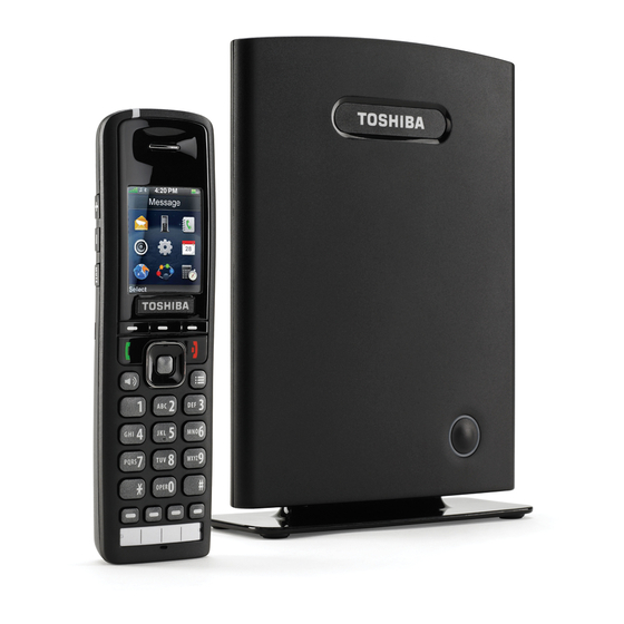
Page 26: Base Station
Figure 1-2 Base Station Rear View Base Station Power The IP4100 Base Station requires Power Over Ethernet. 1. Connect a standard Ethernet cable (Cat 5 or higher) to the Ethernet/ PoE jack on the rear of the base station. Route the cable through the... -
Page 27: Base Station Wall Mount
Be sure the wall material can hold the weight of the base station. 1. Hold the base in its final location and mark the screw location based on the measurements shown. 2. Insert the appropriate anchors for the wall material. IP4100 Install Sept., 2013... -
Page 28: Base Station Desk Mount
Figure 1-4 Base Station Mounting Dimensions Base Station Desk Mount The base station can be placed on a desk or shelf. 1. Attach the Base Station Desk Stand. Refer to Figure 1-1. 2. Connect the IP cable. Refer to Figure 1-4. IP4100 Install Sept., 2013... -
Page 29: Handset And Charger
HANDSET and CHARGER Charging the Battery HANDSET and CHARGER The figure below shows the IP4100 handset and the Charger. TOSHIBA Figure 1-5 Handset Front View and Charger Top View Charging the Battery 1. Install the handset battery as shown below. -
Page 30: Installing The Handset Battery
Insert battery-lay flat, Replace battery cover push gently to snap battery into place Figure 1-6 Installing the Handset Battery Important! Charge each battery completely (about 10 hours) before using it. Figure 1-7 Insert Handset/Battery Into Charger IP4100 Install Sept., 2013... -
Page 31: Powering On The Handset
To power down the handset, press and hold End until the display turns off, about four seconds. INITIAL SYSTEM The IP4100 base stations will be installed in a network environment CONFIGURATION where the following are already installed and functioning: •... -
Page 32: Base Station Interface
IP address. To exit IP Search, press End twice. B. If your network supports Dynamic DNS, then type ipdect<{MAC}> in the address bar of your browser (just insert the MAC address of the base station in place of {MAC}). 1-10 IP4100 Install Sept., 2013... -
Page 33: Home/Status Screen
Open any configuration screen by clicking its name on the left side of the configuration screen; the screen name links appear on every screen. Note: The Repeater menu is NOT used in any configuration for the Strata CIX, IPedge or VIPedge systems. IP4100 Install Sept., 2013 1-11... -
Page 34: General System Configuration
System Syslog Port.) Then, in the Syslog Level field, select one of the following: • Off: no system events are logged. • Normal Operation: This will output normal operation event logs targeted for an administrative audience. Event logs 1-12 IP4100 Install Sept., 2013... -
Page 35: Change Default Password
Country screen. 2. Select the country that best represents the PSTN standards the system should use. 3. Click Save & Reboot. When the base station finishes rebooting, the interface will use the new language. IP4100 Install Sept., 2013 1-13... -
Page 36: Configure The Network Settings
1. In the left hand panel, select Network. This opens the Network Settings screen. Note: Toshiba recommends using static IP addresses. Figure 1-10 Network Settings Screen 2. Enter the correct settings for your network and click Save. Refer to Chapter 3 – Software Reference if you need more information on these fields. -
Page 37: Configure Time Settings
– Check the Home/Status screen to be sure the time has updated correctly. – Check the Time screen to verify that the time server IP address is still correct. Figure 1-11 Checking Time Settings Updates IP4100 Install Sept., 2013 1-15... -
Page 38: Configuring Sip Server Settings
If there is a SIP Proxy, between the base station and the IPedge or Strata CIX system, enter the IP address of the SIP Proxy. If desired, you can add the port number after the IP address using the format {IPaddress}:{port} (e.g., 192.168.250.111:5060). (Sheet 1 of 2) 1-16 IP4100 Install Sept., 2013... -
Page 39: Edit An Existing Server
500/2 = 250 seconds. If the number of seconds is 700, then the re-registration frequency will be 700 - 300 = 400 seconds. Toshiba recommends setting the Re-registration Time to 60. DTMF Signalling Ensure that the type of DTMF signalling is set to RFC 2833. -
Page 40: Add Extension Screen
Select the IPedge or Strata CIX system this extension is programmed on. Forwarding Unconditional Forward all calls: Enter the number the system should forward calls to. Number Select Enable to turn call forwarding on or Disable to leave it off. (Sheet 1 of 2) 1-18 IP4100 Install Sept., 2013... -
Page 41: Edit An Extension
Select Enable to turn call forwarding on or Disable to leave it off. Note: The forwarding in this table refers to the call forwarding capabilities of the IP4100 system. This is separate from the telephone system call forward features. -
Page 42: Register Handsets To Extensions
8. Verify that the Extension and Display Name are correct and that the State shows SIP Registered. 9. Make a quick test call to verify the handset is correctly registered. 10. Repeat the process for each extension. 1-20 IP4100 Install Sept., 2013... -
Page 43: Deregister A Handset
OR click Cancel to leave the handset registered to this extension. MULTIPLE BASE (MULTI- To install a IP4100 system with more than one base, you must configure it CELL) SYSTEMS as a multi-cell system. This section explains how to configure multi-cell systems. -
Page 44: Sample Multi-Cell System
Figure 1-17 shows an example of a multi-cell system, and Table 5 summarizes the parameters for this example. This information is used throughout the instructions. Figure 1-17 Sample Multi-cell System 1-22 IP4100 Install Sept., 2013... -
Page 45: Multi-Cell System Setup
“Configure Level 1 Base Stations” page 1-25. 1. Place the primary base station at its final location. (See the Network Planning Guide for information on the proper placement of base stations.) 2. Login to the base station. IP4100 Install Sept., 2013 1-23... -
Page 46: Multi-Cell Screen (Default Values)
Address on the Home/status screen shows RPN:00 at the end of the field. After a few minutes, the System Information field also updates to display the new status. Figure 1-19 Home/Status Screen (Primary Base Enabled) 1-24 IP4100 Install Sept., 2013... -
Page 47: Configure Level 1 Base Stations
10. In the Number of SIP accounts before distributed load field, enter the maximum number of handset registrations (up to 30) for each base station. This number is synchronized among all the bases in the chain, so you only have to enter it once. IP4100 Install Sept., 2013 1-25... -
Page 48: Base Station Group Table, Synchronizing (Multi-Cell Screen)
• The DECT Chain appears at the bottom of the display and shows the synchronization source for all base stations in this system. Until the primary base station is selected as the DECT sync 1-26 IP4100 Install Sept., 2013... -
Page 49: Configure Level 2 (And Up) Base Stations
2. Login to the base station. 3. Reset the base station to its default settings (open the Management screen and click Default Base Station). If this base station has never been configured, skip this step. IP4100 Install Sept., 2013 1-27... -
Page 50: Base Station Group Table, Level 2 Added (Multi-Cell Screen)
9. After you have configured all the base stations at Level 2, follow the same procedure for the base stations at Level 3, Level 4, and so on, until all base stations have been added to the system. 1-28 IP4100 Install Sept., 2013... -
Page 51: Removing Base Station(S)
2. Go to the Multi Cell screen. 3. In the Base Station Group table, determine which base station you want to become the new primary base station. 4. Select this base station's own RPN as the DECT Sync Source. IP4100 Install Sept., 2013 1-29... -
Page 52: System Maintenance
UPDATING THE You can update the firmware on base stations and handsets remotely via FIRMWARE a TFTP server. Update software files are available from Toshiba’s FYI website. Note: The Base Stations and the Handsets must have the same version firmware (i.e.: v0306). -
Page 53: Firmware Folder Setup
Valid server, folder, and firmware file name example (handsets): tftp://192.168.10.207/Pegasus/PegasusSW_4181_v0306.fwu Configure Firmware Login to the base station interface (refer to “BASE STATION Update Settings INTERFACE” page 1-10), and go to the Firmware Update screen (Figure 1-25). Figure 1-25 Firmware Update Server Information IP4100 Install Sept., 2013 1-31... -
Page 54: Update Handsets
Be sure to perform this update outside of normal business hours. To finalize a firmware update, each handset must be placed in its charger. Be sure your end users return the handsets to the chargers before an update. 1-32 IP4100 Install Sept., 2013... -
Page 55: Update Base Station Firmware
It is recommended to perform this update after normal business hours. Before starting an update, ensure that the TFTP Server is running. 1. Backup the the configuration and save to a PC before starting the next step. In the Configuration menu select Save. IP4100 Install Sept., 2013 1-33... -
Page 56: Firmware Update Screen
To verify the firmware update, go to the Home/Status screen and check the Firmware-Version field. The field shows the current firmware version in the format IPDECT/{Required FW version}/ {date of FW file}, so in this example, the field should read 1-34 IP4100 Install Sept., 2013... -
Page 57: Verify Firmware Update
1. On the front of the handset, press the Menu key. 2. Select Settings, then select Status. 3. Under SW version, make sure the three digits after the period match the Required version, and the line directly below shows the current date and time. IP4100 Install Sept., 2013 1-35... - Page 58 This page is intentionally left blank.
-
Page 59: Chapter 2 - Configuration For Ipedge
Conference Support IPedge systems running R1.5 and later software support multiple SIP channels per station, this allows the IP4100 to receive a call (call waiting notification) when it is already on a call. In Enterprise Manager select Station > Station Assignment. Select the SIP station DN and edit. Click on the Show advanced configuration link. - Page 60 5. Click on the Save, as shown below. Do not exit this utility until you have tested the new features. 6. Make a test call with an IP4100 handset to ensure that the Conferencing soft keys, such as Conf and Swap, now appear on the IP4100 handsets.
-
Page 61: Base Station Configuration
Syslog Review system level messages of the current base station. SIP Log Review IPedge or Strata CIX system related messages to and from the current base station. Logout Exit the base station configuration interface. IP4100 Install Sept., 2013... -
Page 62: Global Buttons And Options
Save changes made on this screen. Clear all changes on this screen and Cancel revert to the previous values. Refresh the screen and reload all values Refresh/Reload from the connected base station. Home/Status Screen (Read Only) IP4100 Install Sept., 2013... -
Page 63: Extensions Screen
The address of the server this base station uses for firmware updates. SIP Identity Status The status of all handsets registered to this base station, in the format on this Base station {Extension}@{IP address of the IPedge or Strata CIX system}. Extensions Screen IP4100 Install Sept., 2013... -
Page 64: Extensions Options
RPN ID of the base station the handset is registered to. FW Info The firmware version of the handset. When updating the handset firmware, this field displays the FWU Progress progress of the update. IP4100 Install Sept., 2013... -
Page 65: Add Extension And Edit Extension
Disable to leave it off. Forwarding on Busy Number Forward on busy: Enter the number the system should forward calls to when this extension is busy. Select Enable to turn call forwarding on or Disable to leave it off. IP4100 Install Sept., 2013... -
Page 66: Servers Screen
Figure 3-1 Servers Screen Table 3-6 Servers Options Option Description Add Server Provision a new IPedge or Strata CIX system for the IP4100 system. Remove Server Remove the selected SIP server from the system. Table 3-7 Servers Parameters Parameter Description •... - Page 67 Set the priority to G711U. Click on any other codec that appears on the Codec Priority list then Remove to remove the codec from the list. To restore the codec list to its original values and order, click Reset. (Sheet 2 of 2) IP4100 Install Sept., 2013...
-
Page 68: Network Screen
(static IP address only) Enter the IP addresses of the main (primary) and backup (secondary) servers where this base station should (Primary and Secondary) direct Domain Name System (DNS) queries. IP4100 Install Sept., 2013... -
Page 69: Vlan Settings Parameters
Keep Alive messages according to the Keep Alive time. Otherwise, leave this feature Disabled. Enter the number of seconds (as a positive integer) between Keep alive time each keep-alive message sent to maintain NAT address assignments. The default value is 90. IP4100 Install Sept., 2013... -
Page 70: Management Screen
Enter the number of ports that can be used for RTP audio RTP port range streaming (the default is 40). Enter the Type of Service or Quality of Service priority code RTP ToS/QoS for RTP traffic; the default is 0xB8. Figure 3-3 Management Screen 3-10 IP4100 Install Sept., 2013... -
Page 71: Management Settings Parameters
System Analyze: Handset roaming events are logged at this level plus Normal Operation logs. The intended audience is Level 1 or 2 technical support. • Debug: Low level debug logs plus System Analyze logs. The intended audience are system developers. IP4100 Install Sept., 2013 3-11... -
Page 72: Firmware Update Screen
0 before clicking, then click Save. Start update Start the firmware update for the base station(s). Updating the firmware will reboot the base station(s) and disconnect any calls. 3-12 IP4100 Install Sept., 2013... -
Page 73: Firmware Update Settings Parameters
This field must match the last 3 digits of the name of the firmware file. Update this base station only Update the firmware on the currently connected base station. Update all base stations Update the firmware on all base stations in this system. IP4100 Install Sept., 2013 3-13... -
Page 74: Country Screen
Country Screen Select the country that best represents the tones and emergency dialing you want to use for the system. Reboot the base station to activate the new setting. 3-14 IP4100 Install Sept., 2013... -
Page 75: Web Security Screen
Central Directory Screen Enter the filename (CSV file) of a contact list you want to import into the IP4100 system’s central directory, then click Load. Important! Importing a new file will replace the existing contact list. The format of an entry in the CSV file is: “name”,”xtension”... -
Page 76: Multi Cell Screen
Enter the unique identifier of the chain you want System chain ID this base station to belong to. Enter the number of seconds between each re- Synchronization time (s) synchronization between this base station and the other base stations in the same chain. 3-16 IP4100 Install Sept., 2013... -
Page 77: Dect System Settings Parameters
SIP support for multiple Select Enabled to allow more than one handset to use the same registrations per account extension or SIP account; if this feature is not supported by the IP telephone system, this field is disabled. IP4100 Install Sept., 2013 3-17... -
Page 78: Base Station Group Parameters
Free Running: The base station was locked, but it has since lost its synchronization source. Unknown: There is no current connection to the base station. Base station Displays the name of each base station (as configured on the Management name screen) 3-18 IP4100 Install Sept., 2013... -
Page 79: Configuration Screen (Read Only)
BASE STATION CONFIGURATION Multi Cell Screen Figure 3-5 Configuration Screen (Read Only) IP4100 Install Sept., 2013 3-19... -
Page 80: Syslog Screen (Read Only)
BASE STATION CONFIGURATION Multi Cell Screen Figure 3-6 Syslog Screen (read only) 3-20 IP4100 Install Sept., 2013... -
Page 81: Sip Log Screen (Read Only)
BASE STATION CONFIGURATION Multi Cell Screen Figure 3-7 SIP Log Screen (read only) IP4100 Install Sept., 2013 3-21... - Page 82 This page is intentionally left blank.
-
Page 83: Chapter 4 - Rfpi Numbers
Equipment Installer's Code (EIC), characters 2 through 5 A preset code that allows terminals to distinguish between separate DECT networks. The minimum value is 0000; the maximum is FFFF. The default value for the IP4100 system is 16E6. • Fixed Part Number (FPN), characters 6 through 8: A geographically unique identity transmitted to DECT networks to help distinguish between communications in different cells or chains. - Page 84 This page is intentionally left blank.
-
Page 85: Chapter 5 - Multiple Primary
Auto Configure Multi Primary and manually configure the DECT chain. Multi Primary is designed to have multiple IP4100 Systems that are not visible via DECT, share a common DECT Chain ID and communicate on the wire only. -
Page 86: Multi Cell Setup
18. In the Base Station Group section, on the line with IP Status showing “This Unit” set the DECT sync source to; Select as primary. 19. Click on the Save button above the Base Station Group. IP4100 Install Sept., 2013... -
Page 87: Multi Primary Base Station Setting
MULTIPLE PRIMARY SETUP 20. Click on the Force reboot chain button at the bottom of the screen. Figure 5-2 Multi Primary Base Station Setting IP4100 Install Sept., 2013... - Page 88 THIS IS THE END OF THE DOCUMENT.