Table of Contents
Advertisement
Quick Links
Advertisement
Table of Contents

Related Manuals for Supermicro SUPERO X10DRU-i+


Summary of Contents for Supermicro SUPERO X10DRU-i+
- Page 1 X10DRU-i+ USER’S MANUAL Revision 1.0a...
- Page 2 This product, including software and docu- mentation, is the property of Supermicro and/or its licensors, and is supplied only under a license. Any use or reproduction of this product is not allowed, except as expressly permitted by the terms of said license.
-
Page 3: About This Motherboard
Infrastructure, MCTP Protocol, and Intel® Node Manager 3.0. This motherboard is ideal for SMCI 1U/2U Ultra server platforms. Please refer to our website (http:// www.supermicro.com) for CPU and memory support updates. Manual Organization Chapter 1 describes the features, specifications and performance of the moth- erboard. -
Page 4: Conventions Used In The Manual
X10DRU-i+ Motherboard User’s Manual Conventions Used in the Manual Pay special attention to the following symbols for proper system installation: Warning: Important information given to ensure proper system installation or to prevent damage to the components or injury to yourself; Note: Additional information given to differentiate between models or instructions provided for proper system setup. -
Page 5: Contacting Supermicro
Super Micro Computer, Inc. 980 Rock Ave. San Jose, CA 95131 U.S.A. Tel: +1 (408) 503-8000 Fax: +1 (408) 503-8008 Email: marketing@supermicro.com (General Information) support@supermicro.com (Technical Support) Web Site: www.supermicro.com Europe Address: Super Micro Computer B.V. Het Sterrenbeeld 28, 5215 ML... -
Page 6: Table Of Contents
Slow Blinking LED for Suspend-State Indicator ........... 1-13 Power Supply ....................1-13 Advanced Power Management ..............1-14 Intel Intelligent Power Node Manager (NM) (Available when the Supermicro ® Power Manager "SPM" is Installed) .............. 1-14 Management Engine (ME) ................1-14 Chapter 2 Installation Standardized Warning Statements .............. - Page 7 Table of Contents NMI Button ....................2-20 Power LED ....................2-20 HDD LED/UID Switch ................2-21 Overheat (OH)/Fan Fail/PWR Fail/UID LED ..........2-22 Power Fail LED ..................2-22 Reset Button ................... 2-23 Power Button ................... 2-23 Connecting Cables ..................2-24 Power Connectors ...................
- Page 8 X10DRU-i+ Motherboard User’s Manual Chapter 4 BIOS Introduction ...................... 4-1 Main Setup ...................... 4-2 Advanced Setup Configurations..............4-4 Event Logs ....................4-31 IPMI ....................... 4-33 Security Settings ................... 4-35 Boot Settings ....................4-36 Save & Exit ....................4-38 Appendix A BIOS Error Beep Codes BIOS Error Beep Codes .................A-1 Appendix B Software Installation Instructions Installing Software Programs ................B-1...
-
Page 9: Chapter 1 Overview
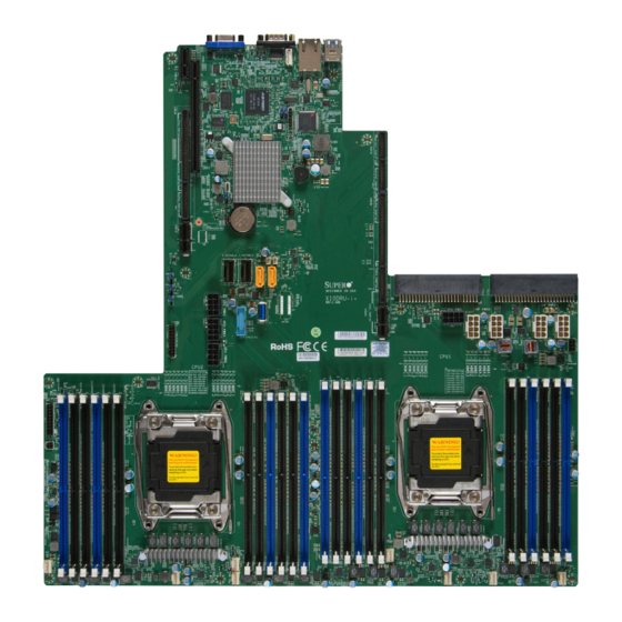
Checklist Congratulations on purchasing your computer motherboard from an acknowledged leader in the industry. Supermicro boards are designed with the utmost attention to detail to provide you with the highest standards in quality and performance. The X10DRU-i+ motherboard was designed to be used with a Supermicro-proprie- tary chassis as an integrated server platform. - Page 10 X10DRU-i+ Motherboard User’s Manual X10DRU-i+ Motherboard Image Note: All graphics shown in this manual were based upon the latest PCB Revision available at the time of publishing of the manual. The motherboard you've received may or may not look exactly the same as the graphics shown in this manual.
-
Page 11: Motherboard Layout
BP PWR2 BP PWR1 GPU PWR1 IPMI CODE BIOS BAR CODE LICENSE X10DRU-i+ Rev. 1.02A CPU1 CPU2 CLOSE 1st CLOSE 1st OPEN 1st OPEN 1st LED_A1 Note: For the latest CPU/Memory updates, please refer to our website at http://www.supermicro.com/products/motherboard/ for details. - Page 12 X10DRU-i+ Motherboard User’s Manual X10DRU-i+ Quick Reference COM1 USB 0/1(3.0) BMC_HB_LED1 IPMI_LAN BIOS JBT1 JBAT1 PSU2 PSU1 I-SATA0~3 JGPW1 BP PWR1 BP PWR2 GPU PWR1 IPMI CODE BIOS BAR CODE LICENSE X10DRU-i+ Rev. 1.02A CPU1 CPU2 CLOSE 1st CLOSE 1st OPEN 1st OPEN 1st LED_A1...
-
Page 13: Connectors Description
SXB3A/3B/3C SMCI-proprietary PCI-E slot used for Ultra Riser devices (supported by CPU1) Note: For additional LAN connections, please install an Ultra riser card on this slot Also, refer to http://www.supermicro.com/support/resources/aoc/ aoc_compatibility_ultra.cfm for more info. I-SGPIO2 Seria_link General Purpose I/O (GPIO) header (for S-SATA ports) Internal speaker/buzzer (BP) USB 0/1 (3.0) - Page 14 X10DRU-i+ Motherboard User’s Manual (FP) USB 2 (3.0) Type A USB 3.0 header for front chassis access (FP) USB 3/4 (3.0) Front-accessible USB 3.0 connections 3/4 Backpanel VGA Port (JVGA1) X10DRU-i+ LED Indicators Description State Status BMC_HB_LED1 BMC Heartbeat LED (Green: Blinking) BMC Normal LED1 Rear UID LED (Blue: On)
-
Page 15: Motherboard Features
2133/1866/1600 MHz modules in 24 DIMM slots. Notes: 1. Memory speed support is depending on the CPUs used in the motherboard. For the latest CPU/memory updates, please refer to our website at http://www.supermicro.com/products/ motherboard. Please also refer to the DDR4 Memory Configuration Guide at http://www. supermicro.com/support/resources/memory/ X10_memory_config_guide.pdf”... -
Page 16: Peripheral Devices
X10DRU-i+ Motherboard User’s Manual I/O Devices SATA Connections • SATA Ports Six (6) SATA 3.0/2.0 connec- tions supported by Intel PCH (I-SATA0~3, I-SATA4/5), • Four (4) SATA connections supported by Intel SCU (S- SATA 0~3) • RAID RAID 0, 1, 10, 5 IPMI 2.0 •... - Page 17 Power-on mode for AC power recovery • Intel Intelligent Power Node Manager 3.0 (Available ® when the Supermicro Power Manager "SPM" is in- stalled and special power supply used. See the note on Page 1-14.) • Management Engine (ME) System...
-
Page 18: System Block Diagram
X10DRU-i+ Motherboard User’s Manual DDR3 NCSI UART Port A Port B Port B Onboard TPM (Optional) 8~15 Port C 0~10 Port 0, 1 Port 3 Port C Rear Type A 11~15 QPI1 QPI0 PE1 PE2 PE3 PE1 PE2 PE3 QPI1 QPI0 Processor Processor... -
Page 19: Processor And Chipset Overview
Chapter 1: Overview Processor and Chipset Overview Built upon the functionality and capability of the Intel E5-2600v3 series processors (Socket R3) and the Intel C612 PCH, the X10DRU-i+ motherboard provides the best balanced solution of performance, power efficiency, and features ideal for enterprise computing and traditional data center environments. -
Page 20: Special Features
X10DRU-i+ Motherboard User’s Manual Special Features Recovery from AC Power Loss The Basic I/O System (BIOS) provides a setting that determines how the system will respond when AC power is lost and then restored to the system. You can choose for the system to remain powered off (in which case you must press the power switch to turn it back on), or for it to automatically return to the power-on state. -
Page 21: Acpi Features
Chapter 1: Overview ACPI Features ACPI stands for Advanced Configuration and Power Interface. The ACPI specifica- tion defines a flexible and abstract hardware interface that provides a standard way to integrate power management features throughout a PC system, including its hardware, operating system and application software. This enables the system to automatically turn on and off peripherals such as CD-ROMs, network cards, hard disk drives and printers. -
Page 22: Advanced Power Management
Intel Intelligent Power Node Manager (NM) (Available ® when the Supermicro Power Manager "SPM" is Installed) The Intel Intelligent Power Node Manager 3.0 (IPNM) provides your system with ® real-time thermal control and power management for maximum energy efficiency. -
Page 23: Chapter 2 Installation
The following statements are industry-standard warnings, provided to warn the user of situations which have the potential for bodily injury. Should you have questions or experience difficulty, contact Supermicro's Technical Support department for assis- tance. Only certified technicians should attempt to install or configure components. - Page 24 X10DRU-i+ Motherboard User’s Manual Attention Danger d'explosion si la pile n'est pas remplacée correctement. Ne la remplacer que par une pile de type semblable ou équivalent, recommandée par le fabricant. Jeter les piles usagées conformément aux instructions du fabricant. ¡Advertencia! Existe peligro de explosión si la batería se reemplaza de manera incorrecta.
-
Page 25: Product Disposal
Chapter 2: Installation Product Disposal Warning! Ultimate disposal of this product should be handled according to all national laws and regulations. 製品の廃棄 この製品を廃棄処分する場合、 国の関係する全ての法律 ・ 条例に従い処理する必要が あります。 警告 本产品的废弃处理应根据所有国家的法律和规章进行。 警告 本產品的廢棄處理應根據所有國家的法律和規章進行。 Warnung Die Entsorgung dieses Produkts sollte gemäß allen Bestimmungen und Gesetzen des Landes erfolgen. -
Page 26: Static-Sensitive Devices
X10DRU-i+ Motherboard User’s Manual القىانين واللىائح الىطنية جميع وفقا ل ينبغي التعامل معه هذا المنتج من التخلص النهائي عند 경고! 이 제품은 해당 국가의 관련 법규 및 규정에 따라 폐기되어야 합니다. Waarschuwing De uiteindelijke verwijdering van dit product dient te geschieden in overeenstemming met alle nationale wetten en reglementen. -
Page 27: Motherboard Installation
Chapter 2: Installation Motherboard Installation All motherboards have standard mounting holes to fit different types of chassis. Make sure that the locations of all the mounting holes for both motherboard and chassis match. Although a chassis may have both plastic and metal mounting fas- teners, metal ones are highly recommended because they ground the motherboard to the chassis. -
Page 28: Installing The Motherboard
X10DRU-i+ Motherboard User’s Manual Installing the Motherboard Note: Always connect the power cord last, and always remove it before adding, removing or changing any hardware components 1. Locate the matching mounting holes on the chassis. Align the mounting holes on the motherboard against the mounting holes on the chassis. 2. -
Page 29: Processor And Heatsink Installation
CPU socket cap is in place and none of the socket pins are bent; otherwise, contact your retailer immediately. • Refer to the Supermicro website for updates on CPU support. Installing the LGA2011 Processor 1. There are two load levers on the LGA2011 socket. To open the socket cover, first press and release the load lever labeled 'Open 1st'. - Page 30 X10DRU-i+ Motherboard User’s Manual 2. Press the second load lever labeled 'Close 1st' to release the load plate that covers the CPU socket from its locking position. Pull lever away from Press down on Load the socket Lever 'Close 1st' 3.
- Page 31 Chapter 2: Installation 4. Use your thumb and the index finger to loosen the lever and open the load plate. 5. Using your thumb and index finger, hold the CPU on its edges. Align the CPU keys, which are semi-circle cutouts, against the socket keys. Socket Keys CPU Keys 6.
- Page 32 X10DRU-i+ Motherboard User’s Manual 7. With the CPU inside the socket, inspect the four corners of the CPU to make sure that the CPU is properly installed. Gently close Push down and lock the the load plate. lever labelled 'Close 1st'. 8.
-
Page 33: Installing A Passive Cpu Heatsink
Chapter 2: Installation Installing a Passive CPU Heatsink 1. Apply the proper amount of thermal grease to the heatsink. 2. Place the heatsink on top of the CPU so that the two mounting holes on the heatsink are aligned with those on the retention mechanism. 3. -
Page 34: Removing The Passive Heatsink
X10DRU-i+ Motherboard User’s Manual Removing the Passive Heatsink Warning: We do not recommend that the CPU or the heatsink be removed. However, if you do need to remove the heatsink, please follow the instructions below to uninstall the heatsink to avoid damaging the CPU or other components. 1. -
Page 35: Installing And Removing The Memory Modules
Chapter 2: Installation Installing and Removing the Memory Modules Note: Check Supermicro's website for recommended memory modules. CAUTION Exercise extreme care when installing or removing DIMM modules to prevent any possible damage. Installing & Removing DIMMs 1. Insert the desired number of DIMMs into the memory slots, starting with P1-DIMMA1. - Page 36 Note1: Memory speed support is depending on the CPUs used in the motherboard. For the latest CPU/memory updates, please refer to our website at http://www.supermicro.com/products/motherboard. For more information on DDR4 memory, please also refer to the DDR4 Memory Configuration Guide at http://www.supermicro.com/support/resources/ memory/X10_memory_config_guide.pdf”...
-
Page 37: Control Panel Connectors And I/O Ports
Chapter 2: Installation Control Panel Connectors and I/O Ports The I/O ports are color coded in conformance with the industry standards. See the picture below for the colors and locations of the various I/O ports. Back Panel Connectors and I/O Ports IPMI CODE BIOS BAR CODE... -
Page 38: Serial Port
X10DRU-i+ Motherboard User’s Manual Serial Port Serial Port (COM1) Pin Definitions A serial port (COM1) is located on the Pin # Definition Pin # Definition IO back panel on the motherboard. See the table on the right for pin definitions. Ground Video Connection A Video (VGA) port is located next to... -
Page 39: Universal Serial Bus (Usb)
RJ45 type cable. Please refer to the LED Indicator Section for LAN LED information. Note: Also, for additional LAN connections, please install an appropriate Ultra riser card on Slot SXB3A/3B/3C. Please refer to the AOC list posted at http://www.supermicro.com/support/resources/aoc/aoc_compatibility_ul- tra.cfm for more info. 1. Backpanel USB0 (USB3.0) COM1 USB 0/1(3.0) -
Page 40: Unit Identifier Buttons/Uid Led Indicators
IPMI, please refer to Power Fail LED 3.3V the IPMI User's Guide posted on our Reset Reset Button Ground website @http://www.supermicro. Power Button Ground com. Front Control Panel (JF1) 1. UID Button (on the I/O Back Panel) COM1 USB 0/1(3.0) -
Page 41: Front Control Panel
These connectors are designed specifically for use with Supermicro's server chassis. See the figure below for the descriptions of the various control panel buttons and LED indicators. Refer to the following section for descriptions and pin definitions. -
Page 42: Front Control Panel Pin Definitions
X10DRU-i+ Motherboard User’s Manual Front Control Panel Pin Definitions NMI Button NMI Button Pin Definitions (JF1) The non-maskable interrupt button Pin# Definition header is located on pins 19 and 20 Control of JF1. Refer to the table on the right Ground for pin definitions. -
Page 43: Hdd Led/Uid Switch
Chapter 2: Installation HDD LED/UID Switch HDD LED/UID Switch Pin Definitions (JF1) The HDD LED/UID switch connection Pin# Definition is located on pins 13 and 14 of JF1. UID Switch Attach a cable to pin 14 to show HDD HD Active activity status. -
Page 44: Overheat (Oh)/Fan Fail/Pwr Fail/Uid Led
X10DRU-i+ Motherboard User’s Manual Overheat (OH)/Fan Fail/PWR Fail/ OH/Fan Fail/ PWR Fail/Blue_UID UID LED LED Pin Definitions (JF1) Pin# Definition Connect an LED cable to pins 7 and Blue_UID LED 8 of JF1 to use the Overheat/Fan Fail/ Power Fail and UID LED connections. OH/Fan Fail/Power Fail The red LED on pin 8 provides warn- OH/Fan Fail/PWR Fail... -
Page 45: Reset Button
Chapter 2: Installation Reset Button Reset Button Pin Definitions (JF1) The Reset Button connection is located Pin# Definition on pins 3 and 4 of JF1. Attach it to a Reset hardware reset switch on the computer Ground case. Refer to the table on the right for pin definitions. -
Page 46: Connecting Cables
X10DRU-i+ Motherboard User’s Manual Connecting Cables Power Connectors The X10DRU-i+ motherboard supports the following power configurations: • Two (2) SMCI-proprietary main power supply units (PSU1: for CPU1 platform support, PSU2: for CPU2 platform support) • Two (2) backplane power-connector units (each unit comprised of two 8-pin power connectors) for backplane device use (BP PWR1: CPU1 platform support, BP PWR2: for CPU2 platform support) •... -
Page 47: Fan Headers
Chapter 2: Installation Fan Header Fan Headers Pin Definitions This motherboard has eight system/CPU fan Pin# Definition headers (Fan 1-Fan 8) on the motherboard. Ground All these 4-pin fans headers are backward +12V compatible with the traditional 3-pin fans. Tachometer However, fan speed control is available for PWR Modulation 4-pin fans only. -
Page 48: Internal Speaker
X10DRU-i+ Motherboard User’s Manual Internal Speaker Internal Buzzer Pin Definition The internal speaker (SP1) can be used Pin# Definitions to provide audible indications for various Pin 1 Pos. (+) Beep In beep codes. See the table on the right for Pin 2 Neg. -
Page 49: Ipmb
Chapter 2: Installation IPMB IPMB Header Pin Definitions A System Management Bus (SMB) Pin# Definition header for IPMI 2.0 is located at JIPMB1. Data Connect the appropriate cable here to Ground use the IPMB I C connection on your Clock system. -
Page 50: Chassis Intrusion
X10DRU-i+ Motherboard User’s Manual Chassis Intrusion Chassis Intrusion Pin Definitions A Chassis Intrusion header is located at JL1 Pin# Definition on the motherboard. Attach an appropriate Intrusion Input cable from the chassis to inform you of a Ground chassis intrusion when the chassis is opened. COM1 USB 0/1(3.0) A. -
Page 51: Jumper Settings
Chapter 2: Installation Jumper Settings Explanation of Jumpers Connector Pins To modify the operation of the mother- board, jumpers can be used to choose between optional settings. Jumpers create Jumper shorts between two pins to change the function of the connector. Pin 1 is identified with a square solder pad on the printed circuit board. -
Page 52: Cmos Clear
X10DRU-i+ Motherboard User’s Manual CMOS Clear JBT1 is used to clear CMOS. Instead of pins, this "jumper" consists of contact pads to prevent accidental clearing of CMOS. To clear CMOS, use a metal object such as a small screwdriver to touch both pads at the same time to short the connection. Note: Please completely shut down the system, and then short JBT1 to clear CMOS. -
Page 53: Vga Enable
Chapter 2: Installation VGA Enable VGA Enable Jumper Settings Jumper JPG1 allows the user to enable Jumper Setting Definition the onboard VGA connector. The default Enabled (Default) setting is 1-2 to enable the connection. Disabled See the table on the right for jumper settings. -
Page 54: Onboard Led Indicators
X10DRU-i+ Motherboard User’s Manual LAN 1/LAN 2 Onboard LED Indicators Link LED Activity LED IPMI-dedicated LAN LEDs An IPMI-dedicated LAN is located on the I/O IPMI LAN IPMI_LAN Activity LED (Right) back panel. The amber LED on the right in- LED State (X8ST3-F) dicates activity, while the other LED on the... -
Page 55: Onboard Power Led
Chapter 2: Installation Onboard Power LED Onboard PWR LED Indicator LED States An Onboard Power LED is located at LED Color Definition LED2 on the motherboard. When this System Off (PWR cable not connected) LED is on, the system is on. Be sure to Green System On turn off the system and unplug the power... -
Page 56: Memory Fault Indication Leds
X10DRU-i+ Motherboard User’s Manual Memory Fault Indication LEDs The memory fault LEDs provide visual notification to a service technician which memory DIMM slot(s) are at fault due to un-correctable memory errors during POST (Power-On Self-Test). A memory fault LED will remain "on" even after system reboots (or repeated "power cycling") until it is reset manually by the technician us- ing the BIOS setup menu to turn it off. -
Page 57: 2-10 Sata Connections
Intel PCH, and S-SATA0-3 are sup- SATA_TXP ported by the Intel SCU. I-SATA4/5 can be used SATA_TXN with Supermicro SuperDOMs which are yellow SATA Ground DOM connectors with power pins built in, and do not SATA_RXN require external cables. Supermicro SuperDOMs are... - Page 58 X10DRU-i+ Motherboard User’s Manual Notes 2-36...
-
Page 59: Chapter 3 Troubleshooting
Chapter 3: Troubleshooting Chapter 3 Troubleshooting Troubleshooting Procedures Use the following procedures to troubleshoot your system. If you have followed all of the procedures below and still need assistance, refer to the ‘Technical Support Procedures’ and/or ‘Returning Merchandise for Service’ section(s) in this chapter. Note: Always disconnect the power cord before adding, changing or installing any hardware components. -
Page 60: System Boot Failure
X10DRU-i+ Motherboard User’s Manual No Video 1. If the power is on, but you have no video, remove all the add-on cards and cables. 2. Use the speaker to determine if any beep codes exist. Refer to Appendix A for details on beep codes. System Boot Failure If the system does not display POST or does not respond after the power is turned on, check the following:... -
Page 61: Memory Errors
2. Memory support: Make sure that the memory modules are supported by test- ing the modules using memtest86 or a similar utility. Note: Refer to the product page on our website http:\\www.supermicro. com for memory and CPU support and updates. - Page 62 X10DRU-i+ Motherboard User’s Manual 4. System cooling: Check system cooling to make sure that all heatsink fans, and CPU/system fans, etc., work properly. Check Hardware Monitoring set- tings in the BIOS to make sure that the CPU and System temperatures are within the normal range.
-
Page 63: Technical Support Procedures
Technical Support Procedures Before contacting Technical Support, please take the following steps. Also, please note that as a motherboard manufacturer, Supermicro also sells motherboards through its channels, so it is best to first check with your distributor or reseller for troubleshooting services. -
Page 64: Battery Removal And Installation
X10DRU-i+ Motherboard User’s Manual Battery Removal and Installation Battery Removal To remove the onboard battery, follow the steps below: 1. Power off your system and unplug your power cable. 2. Locate the onboard battery as shown below. 3. Using a tool such as a pen or a small screwdriver, push the battery lock out- wards to unlock it. -
Page 65: Frequently Asked Questions
Note : The SPI BIOS chip used on this motherboard cannot be removed. Send your motherboard back to our RMA Department at Supermicro for repair. For BIOS Recovery instructions, please refer to the AMI BIOS Recovery Instructions posted at http://www.supermicro.com. -
Page 66: Returning Merchandise For Service
Shipping and handling charges will be applied for all orders that must be mailed when service is complete. For faster service, You can also request a RMA authorization online (http://www.supermicro.com/RmaForm/). This warranty only covers normal consumer use and does not cover damages in- curred in shipping or from failure due to the alternation, misuse, abuse or improper maintenance of products. -
Page 67: Chapter 4 Bios
Chapter 4: AMI BIOS Chapter 4 BIOS Introduction This chapter describes the AMI BIOS setup utility for the X10DRU-i+. It also provides the instructions on how to navigate the AMI BIOS setup utility screens. The AMI ROM BIOS is stored in a Flash EEPROM and can be easily updated. Starting BIOS Setup Utility To enter the AMI BIOS setup utility screens, press the <Del>... -
Page 68: Main Setup
<F2> at the appropriate time during system boot. Note: For AMI UEFI BIOS Recovery, please refer to the UEFI BIOS Recov- ery User Guide posted @ http://www.supermicro.com/support/manuals/. Starting the Setup Utility Normally, the only visible Power-On Self-Test (POST) routine is the memory test. - Page 69 This item displays the system date in Day MM/DD/YY format (e.g. Wed 10/12/2011). System Time This item displays the system time in HH:MM:SS format (e.g. 15:32:52). Supermicro X10DRU-i+ BIOS Version This item displays the version of the BIOS ROM used in this system.
-
Page 70: Advanced Setup Configurations
X10DRU-i+ Motherboard User’s Manual Advanced Setup Configurations Use the arrow keys to select Advanced Setup and press <Enter> to access the following submenu items. Boot Features Quiet Boot This feature selects the bootup screen display between POST messages and the OEM logo. Select Disabled to display the POST messages. Select Enabled to display the OEM logo instead of the normal POST messages. -
Page 71: Power Configuration
Chapter 4: AMI BIOS INT19 (Interrupt 19) Trap Response Interrupt 19 is the software interrupt that handles the boot disk function. When this item is set to Immediate, the ROM BIOS of the host adaptors will "capture" Interrupt 19 at bootup immediately and allow the drives that are attached to the host adap- tors to function as bootable disks. -
Page 72: Cpu Configuration
X10DRU-i+ Motherboard User’s Manual CPU Configuration This submenu displays the information of the CPU as detected by the BIOS. It also allows the user to configuration CPU settings. Socket 1 CPU Information/Socket 2 CPU Information This submenu displays the following information regarding the CPU installed in Socket 1 and (or) Socket 2 as detected by the BIOS. - Page 73 Chapter 4: AMI BIOS Execute Disable Bit (Available if supported by the OS & the CPU) Select Enable to enable the Execute-Disable Bit which will allow the processor to designate areas in the system memory where an application code can execute and where it cannot, thus preventing a worm or a virus from flooding illegal codes to overwhelm the processor or damage the system during an attack.
-
Page 74: Advanced Power Management Configuration
X10DRU-i+ Motherboard User’s Manual Intel® Virtualization Technology (Available when supported by the CPU) Select Enable to support Intel Virtualization Technology, which will allow one platform to run multiple operating systems and applications in independent parti- tions, creating multiple "virtual" systems in one physical computer. The options are Enable and Disable. - Page 75 Chapter 4: AMI BIOS CPU C State Control Package C-State limit This feature allows the user to set the limit on the C-State package register. The options are C0/C1 State, C2 State, C6 (Non Retention) State, and C6 (Reten- tion) State.
-
Page 76: Chipset Configuration
X10DRU-i+ Motherboard User’s Manual Chipset Configuration North Bridge This feature allows the user to configure the following North Bridge settings. IIO Configuration EV DFX (Device Function On-Hide) Feature When this feature is set to Enable, the EV_DFX Lock Bits that are located on a processor will always remain clear during electric tuning. - Page 77 Chapter 4: AMI BIOS IOU1 (II0 PCIE Port 3) Use this item to configure the PCI-E port Bifuraction setting for a PCI-E port speci- fied by the user. The options are x4x4x4x4, x4x4x8, x8x4x4, x8x8, x16, and Auto. IIO2 Configuration IOU2 (II02 PCIe Port 1) This item configures the PCI-E port Bifuraction setting for a PCI-E port specified by the user.
- Page 78 X10DRU-i+ Motherboard User’s Manual No Snoop Select Enable to support no-snoop mode for each CB device. The options are Disable and Enable. Relaxed Ordering Select Enable to enable Relaxed Ordering support which will allow certain transactions to violate the strict-ordering rules of PCI bus for a transaction to be completed prior to other transactions that have already been enqueued.
- Page 79 Chapter 4: AMI BIOS Link Frequency Select Use this feature to select the desired QPI link frequency. The options are 6.4 GT/s, 8.0 GT/s, 9.6 GT/s, Auto, and Auto Limited. Link L0p Enable Select Enable for the QPI to enter the L0p state for power saving. The options are Disable and Enable.
-
Page 80: Dimm Information
X10DRU-i+ Motherboard User’s Manual Set Throttling Mode Throttling improves reliability and reduces power consumption in the proces- sor via automatic voltage control during processor idle states. The options are Disabled and CLTT (Closed Loop Thermal Throttling). Socket Interleave Below 4GB Select Enable for the memory above the 4G Address space to be split between two sockets. -
Page 81: South Bridge Configuration
Chapter 4: AMI BIOS Patrol Scrub Interval This feature allows you to decide how many hours the system should wait before the next complete patrol scrub is performed. Use the keyboard to enter a value from 0-24. The Default setting is 24. Demand Scrub Demand Scrubbing is a process that allows the CPU to correct correctable memory errors found on a memory module. -
Page 82: Sata Configuration
X10DRU-i+ Motherboard User’s Manual Port 60/64 Emulation Select Enabled for I/O port 60h/64h emulation support, which will provide complete legacy USB keyboard support for the operating systems that do not support legacy USB devices. The options are Disabled and Enabled. USB 3.0 Support Select Enabled for USB 3.0 support. - Page 83 Chapter 4: AMI BIOS the I/O is inactive for an extended period of time, and the power state will return to normal when the I/O becomes active. The options are Enabled and Disabled. SATA Port 0~ Port 5 This item displays the information detected on the installed SATA drive on the particular SATA port.
-
Page 84: Ssata Configuration
X10DRU-i+ Motherboard User’s Manual SATA RAID Option ROM/UEFI Driver Select EFI to load the EFI driver for system boot. Select Legacy to load a legacy driver for system boot. The options are Disabled, EFI, and Legacy. SATA/sSATA RAID Boot Select Select SATA Controller to boot the system from a SATA RAID device. - Page 85 Chapter 4: AMI BIOS Configure sSATA as Select IDE to configure an sSATA drive specified by the user as an IDE drive. Select AHCI to configure an sSATA drive specified by the user as an AHCI drive. Select RAID to configure an sSATA drive specified by the user as a RAID drive. The op- tions are IDE, AHCI, and RAID.
- Page 86 X10DRU-i+ Motherboard User’s Manual Port 0 ~ Port 3 sSATA Device Type (Available when a SATA port is detected) Use this item to specify if the sSATA port specified by the user should be con- nected to a Solid State drive or a Hard Disk Drive. The options are Hard Disk Drive and Solid State Drive.
- Page 87 Chapter 4: AMI BIOS Port 0 ~ Port 3 sSATA Device Type Use this item to specify if the sSATA port specified by the user should be con- nected to a Solid State drive or a Hard Disk Drive. The options are Hard Disk Drive and Solid State Drive.
- Page 88 X10DRU-i+ Motherboard User’s Manual Maximum Payload Select Auto for the system BIOS to automatically set the maximum payload value for a PCI-E device to enhance system performance. The options are Auto, 128 Bytes, and 256 Bytes. Maximum Read Request Select Auto for the system BIOS to automatically set the maximum size for a read request for a PCI-E device to enhance system performance.
- Page 89 Chapter 4: AMI BIOS Onboard Video OPROM Select Legacy to boot the system using a legacy video device installed on the motherboard. The options are Disabled, Legacy and EFI. VGA Priority Use this item to select the graphics device to be used as the primary video display for system boot.
-
Page 90: Serial Port Console Redirection
X10DRU-i+ Motherboard User’s Manual Serial Port Console Redirection COM 1 COM 1 Console Redirection Select Enabled to enable COM Port 1 Console Redirection, which will allow a client machine to be connected to a host machine at a remote site for networking. The options are Disabled and Enabled. - Page 91 Chapter 4: AMI BIOS Flow Control Use this item to set the flow control for Console Redirection to prevent data loss caused by buffer overflow. Send a "Stop" signal to stop sending data when the receiving buffer is full. Send a "Start" signal to start sending data when the receiving buffer is empty.
- Page 92 X10DRU-i+ Motherboard User’s Manual SOL/COM2 Console Redirection Settings Use this feature to specify how the host computer will exchange data with the client computer, which is the remote computer used by the user. Terminal Type Use this feature to select the target terminal emulation type for Console Redirec- tion.
- Page 93 Chapter 4: AMI BIOS VT-UTF8 Combo Key Support Select Enabled to enable VT-UTF8 Combination Key support for ANSI/VT100 terminals. The options are Enabled and Disabled. Recorder Mode Select Enabled to capture the data displayed on a terminal and send it as text messages to a remote server.
-
Page 94: Acpi Settings
X10DRU-i+ Motherboard User’s Manual *If the item above set to Enabled, the following items will become available for user's configuration: EMS Console Redirection Settings Out-of-Band Management Port The feature selects a serial port in a client server to be used by the Windows Emergency Management Services (EMS) to communicate with a remote host server. - Page 95 Chapter 4: AMI BIOS High Precision Timer Select Enabled to activate the High Precision Event Timer (HPET) that produces periodic interrupts at a much higher frequency than a Real-time Clock (RTC) does in synchronizing multimedia streams, providing smooth playback and reducing the de- pendency on other timestamp calculation devices, such as an x86 RDTSC Instruc- tion embedded in the CPU.
- Page 96 X10DRU-i+ Motherboard User’s Manual • TPM Active Status • TPM Owner Status TXT Support Select Enabled to enable TXT (Trusted Execution Technology) settings to improve data and network security. The options are Disabled and Enabled. 4-30...
-
Page 97: Event Logs
Chapter 4: AMI BIOS Event Logs Use this feature to configure Event Log settings. Change SMBIOS Event Log Settings This feature allows the user to configure SMBIOS Event settings. Enabling/Disabling Options SMBIOS Event Log Select Enabled to enable SMBIOS (System Management BIOS) Event Logging during system boot. -
Page 98: View Smbios Event Log
X10DRU-i+ Motherboard User’s Manual Erasing Settings Erase Event Log Select Enabled to erase all error events in the SMBIOS (System Management BIOS) log before an event logging is initialized at bootup. The options are No and Yes. When Log is Full Select Erase Immediately to immediately erase all errors in the SMBIOS event log when the event log is full. -
Page 99: Ipmi
Chapter 4: AMI BIOS IPMI Use this feature to configure Intelligent Platform Management Interface (IPMI) settings. IPMI Firmware Revision This item indicates the IPMI firmware revision used in your system. IPMI Status This item indicates the status of the IPMI firmware installed in your system. System Event Log ... -
Page 100: Bmc Network Configuration
X10DRU-i+ Motherboard User’s Manual When SEL is Full This feature allows the user to determine what the BIOS should do when the sys- tem event log is full. Select Erase Immediately to erase all events in the log when the system event log is full. The options are Do Nothing and Erase Immediately. Note: After making changes on a setting, be sure to reboot the system for the changes to take effect. -
Page 101: Security Settings
Chapter 4: AMI BIOS Security Settings This menu allows the user to configure the following security settings for the system. Password Check Select Setup for the system to prompt for a password at Setup. Select Always for the system to prompt for a password at bootup and upon entering the BIOS setup utility. -
Page 102: Boot Settings
X10DRU-i+ Motherboard User’s Manual Boot Settings Use this feature to configure Boot Settings: Boot Configuration Setup Prompt Timeout Use this item to indicate how many seconds the system shall wait for the BIOS setup activation key to respond before the system starts to boot. The default setting is 1. Boot Mode Select Use this item to select the type of device to be used for system boot. - Page 103 Chapter 4: AMI BIOS • Boot Order #7 • Boot Order #8 • Boot Order #9 • Boot Order #10 • Boot Order #11 • Boot Order #12 • Boot Order #13 • Boot Order #14 • Boot Order #15 ...
-
Page 104: Save & Exit
X10DRU-i+ Motherboard User’s Manual Save & Exit Select the Save & Exit tab from the BIOS setup screen to configure the settings below. Discard Changes and Exit Select this option to quit the BIOS setup without making any permanent changes to the system configuration, and reboot the computer. - Page 105 Chapter 4: AMI BIOS Restore Optimized Defaults To set this feature, select Restore Optimized Defaults from the Exit menu and press <Enter>. These are manufacture default settings designed for maximum system performance. Save As User Defaults To set this feature, select Save as User Defaults from the Exit menu and press <En- ter>.
- Page 106 X10DRU-i+ Motherboard User’s Manual Notes 4-40...
-
Page 107: Appendix A Bios Error Beep Codes
Appendix A: BIOS POST Error Codes Appendix A BIOS Error Beep Codes During the POST (Power-On Self-Test) routines, which are performed at each system boot, errors may occur. Non-fatal errors are those which, in most cases, allow the system to continue to boot. - Page 108 X10DRU-i+ Motherboard User’s Manual Notes...
-
Page 109: Appendix B Software Installation Instructions
Appendix B Software Installation Instructions B-1 Installing Software Programs The Supermicro ftp site contains drivers and utilities for your system at ftp://ftp. supermicro.com. Some of these must be installed, such as the chipset driver. After accessing the ftp site, go into the CDR_Images directory and locate the ISO file for your motherboard. -
Page 110: B-2 Installing Superdoctor5
X10DRU-i+ Motherboard User’s Manual B-2 Installing SuperDoctor5 The Supermicro SuperDoctor® 5 is a hardware monitoring program that functions in a command-line or web-based interface in Windows and Linux operating systems. The program monitors system health information such as CPU temperature, system voltages, system power consumption, fan speed, and provides alerts via email or Simple Network Management Protocol (SNMP). -
Page 111: Appendix C Uefi Bios Recovery Instructions
Flashing the wrong BIOS can cause irreparable damage to the system. In no event shall Supermicro be liable for direct, indirect, special, incidental, or consequential damages arising from a BIOS update. If you need to update the BIOS, do not shut down or reset the system while the BIOS is updating to avoid possible boot failure. - Page 112 Root "\" Directory of a USB device or a writeable CD/DVD. Note: If you cannot locate the "Super.ROM" file in your driver disk, visit our website at www.supermicro.com to download the BIOS image into a USB flash device and rename it "Super.ROM" for BIOS recovery use.
- Page 113 Appendix C: UEFI BIOS Recovery 4. After locating the new BIOS binary image, the system will enter the BIOS Recovery menu as shown below. Note: At this point, you may decide if you want to start with BIOS recovery. If you decide to proceed with BIOS recovery, follow the procedures below. 5.
- Page 114 X10DRU-i+ Motherboard User’s Manual 6. After the process of BIOS recovery is completed, press any key to reboot the system. 7. Using a different system, extract the BIOS package into a bootable USB flash drive. 8. When a DOS prompt appears, enter FLASH.BAT BIOSname.### at the prompt.
- Page 115 (Disclaimer Continued) The products sold by Supermicro are not intended for and will not be used in life support systems, medical equipment, nuclear facilities or systems, aircraft, aircraft devices, aircraft/emergency communication devices or other critical systems whose failure to perform be reasonably expected to result in significant injury or loss of life or catastrophic property damage.
Need help?
Do you have a question about the SUPERO X10DRU-i+ and is the answer not in the manual?
Questions and answers