
Related Manuals for Meyer Sound UPM-1P


Summary of Contents for Meyer Sound UPM-1P
- Page 1 OPERATING INSTRUCTIONS ULTRASERIES UPM-1P Ultra-Compact Wide Coverage Loudspeaker UPM-2P Ultra-Compact Narrow Coverage Loudspeaker Keep these important operating instructions. Check www.meyersound.com for updates.
- Page 2 UltraSeries, RMS and all alpha-numeric designations for Meyer Sound products and accessories are trademarks of Meyer Sound. Meyer Sound, Meyer Sound MAPP Online, SIM, TruPower and QuickFly are registered trademarks of Meyer Sound Laboratories Inc. (Reg. U.S. Pat. & Tm. Off.).
-
Page 3: Table Of Contents
Service Button Wink LED (green) Reset Button Acivity LED (Green) User Interface CHAPTER 4: Using Subwoofers with the UPM-1P and UPM-2P Daisy-Chained Adding a Line Driver Engaging the Lo-Cut Filter Digital Signal Processors CHAPTER 5: System Design and Integration Tools... - Page 4 APPENDIX A: Basic Troubleshooting APPENDIX B: Specifications...
-
Page 5: Introduction
Two-channel power amplifier at hand. Proprietary phase-corrected active processing circuitry Both the UPM-1P and UPM-2P use a 1-inch metal dome tweeter on a symmetrical constant-directivity high-frequen- CAUTION gives notice that an action can cy horn. -
Page 6: Three-Way System
In addition, a The 123 dB peak SPL of the UPM-1P and UPM-2P sophisticated phase correction circuit in the active electron- loudspeakers makes them an excellent choice for use as ics compensates for phase shift in the passive network. - Page 7 ® mounting yoke (MYA-UPM), stand adapter (MSA-UPM) and U-bracket (MUB-UPM)— attach easily to the UPM-1P and UPM-2P allowing them to be mounted or flown, either as a single cabinet or in arrays. The optional RMS remote moni- toring system module allows comprehensive monitoring of all key system parameters on a remote RMS host PC.
- Page 8 INTRODUCTION...
-
Page 9: Chapter 1: Power Requirements
115 or AC POWER 230 volts. When set to 115 volts, the UPM-1P and UPM-2P will operate properly when the AC remains within the range UPM-1P and UPM-2P loudspeakers use a PowerCon ®... -
Page 10: Current Requirements
– do not cause the amplifier to cycle on and off The minimum electrical service amperage required by or cause damage to the power supply. UPM-1P and UPM-2P systems is the sum of each loudspeaker’s maximum continuous rms current. An additional 30 percent above the minimum amperage is... -
Page 11: Electrical Safety Issues
Always use a grounded outlet and plug. Do not use a ground- lifting adapter or cut the AC cable ground pin. CAUTION: Keep all liquids away from the UPM-1P and UPM-2P to avoid hazards from electrical shock. - Page 12 CHAPTER 1...
-
Page 13: Chapter 2: Amplification And Audio
All UPM-1P and UPM-2P loudspeakers are equipped standard with the looping audio input module (Figure 2.2), Figure 2.1. The user panel of the UPM-1P with standard looping Pins 2 and 3 carry the input as a differential signal; pin audio input module and optional RMS 2 is hot relative to pin 3, resulting in a positive pressure wave when a positive signal is applied to pin 2. -
Page 14: Amplification And Limiting
UPM-1P and UPM-2P. If you need the system. The audio source must be capable of providing to replace a UPM-1P or UPM-2P amplifier and/or a minimum of 20 dB volts (10 volts rms into 600 ohms) to control board, please contact Meyer Sound. -
Page 15: Driver Interconnections
Figure 2.4 shows how the UPM-1P and UPM-2P drivers are Increasing the input level will not increase the volume. connected to the amplifier. - Page 16 CHAPTER 2...
-
Page 17: Chapter 3: Rms Remote Monitoring System (Optional)
An optional RMS communication module can be installed in In addition, any loudspeaker can be physically identified the UPM-1P and UPM-2P loudspeakers' lower module slot. from RMS software by activating the Wink function – a Wink LED will turn on the RMS communication board that RMS is a real-time networked monitoring system that corresponds to its Node Name. -
Page 18: Service Button
RMS hardware failure. In this case, the RMS (and the red LED is blinking) the loudspeaker has not been communication module may be damaged and you should contact Meyer Sound Technical Support. installed on the network. NOTE: The LEDs and buttons on the RMS... -
Page 19: Chapter 4: Using Subwoofers With The Upm-1P And Upm-2P
29 Hz and 30 Hz, respectively. NOTE: When a UPM-1P or UPM-2P In addition, the use of high-pass filters to drive a UPM-1P or loudspeaker and a subwoofer are used in UPM-2P system with subwoofers flattens overall frequency their full-range configuration (e.g., looped audio or... -
Page 20: Engaging The Lo-Cut Filter
Using the LD-1A, LD-2 or LD-3 Lo-Cut filter (160 Hz the DSP is near maximum throughput. position on the LD-3) with a system comprising UPM-1P or In no case should a filter higher than 2nd order be used. UPM-2P loudspeakers and subwoofers in close proximity... -
Page 21: Chapter 5: System Design And Integration Tools
CHAPTER 5: SYSTEM DESIGN AND INTEGRATION TOOLS This chapter introduces MAPP, Meyer Sound's patented MAPP client software lets you configure Meyer Sound system design tool, and SIM 3, a comprehensive system for loudspeaker systems and define the environment in which measurement and analysis. -
Page 22: Sim 3 Measurement System
Source Independent Measurement Technique Optimizing subwoofer integration The SIM 3 audio analyzer implements Meyer Sound's Optimizing loudspeaker arrays source independent measurement technique, a dual- The SIM audio analyzer can also be used in the following channel method that accommodates statistically unpredictable excitation signals. -
Page 23: Chapter 6: Quickfly Rigging
STAND-MOUNTING THE UPM-1P AND UPM-2P LOUDSPEAKERS Figure 6.2. The MYA-UPM is used to suspend a single UPM-1P or UPM-2P cabinet You can mount the UPM-1P or UPM-2P loudspeaker on a stand using the MSA-UPM stand adapter (Figure 6.1) along... -
Page 24: Using The Mub-Upm U-Bracket
6.3. Make sure the bolts are well tightened. Wall Mount The MUB-UPM allows you to mount the UPM-1P or UPM- 2P in both a vertical (Figure 6.4) and horizontal orientation (Figure 6.5) for wall mounting. -
Page 25: Floor Mount
CHAPTER 6 Floor Mount The MUB-UPM can also be used to mount the UPM-1P or UPM-2P on the floor or stage lip, which is useful for monitoring or front-fill applications, for example (Figure 6.7). Figure 6.7. Floor-mounting the UPM-1P CAUTION:... - Page 26 CHAPTER 6...
- Page 27 This section contains possible solutions to common prob- 4. Hum or noise can be produced by a ground loop. Since lems encountered by UPM-1P and UPM-2P loudspeaker the UPM-1P and UPM-2P are effectively ground-lifted, users and is not intended to be a comprehensive trouble- the loop must be broken elsewhere in the system.
- Page 28 APPENDIX A...
- Page 29 APPENDIX B APPENDIX B: SPECIFICATIONS ACOUSTICAL — UPM-1P Operating frequency range 75 Hz - 20 kHz Note: Recommended maximum operating frequency range. Response depends on loading conditions and room acoustics. Frequency response 80 Hz - 16 kHz ±4 dB Note: Free field, measured with 1/3-octave frequency resolution at 4 meters.
- Page 30 APPENDIX B AUDIO INPUT — UPM-1P/UPM-2P Type Differential, electronically balanced Max. common mode range ±15 V DC, clamped to earth for voltage transient protection Connectors Female XLR input and male XLR loop output Input impedance 10 kOhms differential between pins 2 and 3...
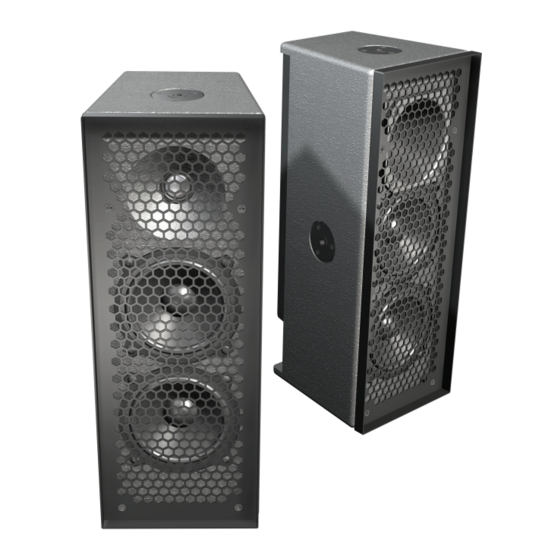
- Page 31 APPENDIX B PHYSICAL — UPM-1P/UPM-2P Enclosure Multi-ply hardwood Finish Black textured Protective grille Hex stamped metal screen frame charcoal-grey foam covering Rigging 3/8”-16 or M10 nut plates Dimensions 6.85” w x 18.00” h x 7.70” d (174 mm x 457 mm x 196 mm) Weight 21 lbs (9.53 kg)/shipping: 24 lbs (10.88 kg)
- Page 32 APPENDIX B...
- Page 36 Meyer Sound Laboratories Inc. 2832 San Pablo Avenue © 2004, 2015 Berkeley, CA 94702 Meyer Sound. All rights reserved. +1 510 486.1166 UPM-1P, UPM-2P Operating Instructions www.meyersound.com PN 05.084.003.01 D...
Need help?
Do you have a question about the UPM-1P and is the answer not in the manual?
Questions and answers