Advertisement
Table of Contents
- 1 Operating Instructions
- 2 Table of Contents
- 3 Introduction
- 4 AC Power
- 5 The Modular Rear Panel
- 6 Amplification, Limiting, and Cooling System
- 7 Rigging
- 8 Full-Range Systems
- 9 Verifying Driver Polarity
- 10 Troubleshooting
- 11 Safety Summary
- 12 Rear Panel and Input Modules Drawings
- 13 Dimensions
- 14 Notes
- 15 Contact Information
- Download this manual
Advertisement
Table of Contents

Related Manuals for Meyer Sound UPA-1P


Summary of Contents for Meyer Sound UPA-1P
-
Page 1: Operating Instructions
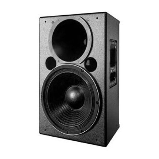
Operating Instructions UPA-P Series UPA-1P and UPA-2P Self-Powered Loudspeakers (Serial Numbers 981000 and above) UPA-1P Copyright © 1997 Meyer Sound Laboratories, Inc. All rights reserved Part #: 05.054.017.01 Rev B Keep these important operating instructions. -
Page 2: Table Of Contents
Vibration: 10 Hz to 55 Hz (0.010m Berkeley, California USA peak-to-peak excursion) October 1, 1994 The following Meyer Sound patents apply to the UPA-P: Made by Meyer Sound Laboratories Berkeley, California USA Des. 271,967 (U.S.A.) European Office: Meyer Sound Lab. GmbH 4,152,552 (U.S.A) -
Page 3: Introduction
10 dB from its on-axis amplitude because many listeners per- ceive -10 dB as a halving in pressure. Meyer Sound defines beamwidth as the angle at which sound pressure decreases 6 dB. -6 dB represents the actual halving of The Integrated Design sound pressure. -
Page 4: Ac Power
length of time the unit will continue to function during AC Power brownout depends on the operating level and how low the voltage drops. The unit turns off if the voltage does not increase above 88V for 1 to 5 seconds. If the UPA-P shuts down due to brownout, the power supply auto- The UPA-P uses a PowerCon locking 3-pole AC mains matically turns on if the voltage returns to the normal... -
Page 5: The Modular Rear Panel
Use the table below as a guide to select cables and circuit breakers with appropriate ratings for your operating voltage. UPA-P Current Ratings Keep all liquids away from the UPA-P to avoid hazards from electrical shock. Do not operate the unit with worn or frayed cables; replace them immediately. -
Page 6: Amplification, Limiting, And Cooling System
P is turned off for any reason. Each driver in the UPA-P is powered by one channel of a Summing Audio Input Module proprietary Meyer Sound amplifier utilizing complemen- tary power MOSFET output stages (class AB, bridged, This module has two balanced female XLR connectors. -
Page 7: Rigging
(85 ° C) during normal operation. Use extreme caution when approaching the rear of the cabinet. NOTE: All Meyer Sound products must be used in accor- dance with local, state, federal, and industry regulations. It is the owner’s and/or user’s responsibility to evaluate Fan Assembly Kit the reliability of any rigging method for their application. - Page 8 • choose, place, and array speakers; • measure propagation delays between speakers to set the correct polarity and delay times; A single UPA-1P paired with a USW-1P provides < 134 dB • measure and equalize variations in frequency re- SPL across 100° of horizontal coverage.
-
Page 9: Verifying Driver Polarity
For a high power, compact system, we recommend using Verifying Driver Polarity two UPA-2Ps and two USW-1Ps. This array provides < 143 dB SPL across 60° of horizontal coverage Incorrect driver polarity impairs system performance and may damage the drivers. All Meyer loudspeakers are shipped with the drivers in correct alignment. -
Page 10: Troubleshooting
Replacement Procedure, and The High Frequency Driver Re- 3. Send the audio signal to another speaker to insure placement Procedure for the UPA-1P/2P. signal presence and that the level is within the proper range. Turn the source level down before reconnect- The On/Temp. - Page 11 The audio produced by the speaker is There is no sound, the On/Temp. LED is highly compressed and the limit light is dim or off, and the power supply fan is on constantly yellow. high speed. 1. Turn down the level of the input signal to the This extremely rare event occurs when the power supply speaker system.
-
Page 12: Safety Summary
• Do not install the loudspeaker in wet or humid locations d’électrocution et peut constituer une infraction à la without using weather protection equipment from Meyer Sound. réglementation locale concernant les installations électriques. • Do not allow water or any foreign object to get inside the •... -
Page 13: Rear Panel And Input Modules Drawings
Rear Panel and Optional Modules The user panel and optional modules are described on page 5 of this guide. User Panel with RMS option and Standard Looping Audio Input Module. Looping, Polarity, and Attenuating Input Module Summing Audio Input Module... -
Page 14: Dimensions
Dimensions (in inches) 7.25 12.8 14.3 14.5 UPA-P Top UPA-P Back 7.25 10.85 10.85 UPA-1P Side UPA-2P Side 22.4 22.4 UPA-1P Front UPA-2P Front Center of gravity represented by "... -
Page 15: Notes
Notes... -
Page 16: Contact Information
Contact Information Meyer Sound Laboratories, Inc. 2832 San Pablo Avenue Berkeley, California 94702 Telephone: 510 - 486 - 1166 FAX: 510 - 486 - 8356 E-mail: techsupport@meyersound.com http://www.meyersound.com...
Need help?
Do you have a question about the UPA-1P and is the answer not in the manual?
Questions and answers