
Related Manuals for Meyer Sound UP-4XP


Summary of Contents for Meyer Sound UP-4XP
- Page 1 OPERATING INSTRUCTIONS ULTRASERIES UP-4XP™ UltraCompact Loudspeaker Keep these important operating instructions. Check www.meyersound.com for updates.
- Page 2 The contents of this manual are furnished for informational purposes only, are subject to change without notice, and should not be con- strued as a commitment by Meyer Sound Laboratories Inc. Meyer Sound assumes no responsibility or liability for any errors or inaccura- cies that may appear in this manual.
-
Page 3: Important Safety Instructions
2. Keep these instructions. 12. If applicable, use only with the caster rails or rigging 3. Heed all warnings. specified by Meyer Sound, or sold with the loudspeaker. 4. Follow all instructions. Handles are for carrying only. 5. Do not use this loudspeaker near water. -
Page 4: Safety Summary
SAFETY SUMMARY ■ ■ English Ne pas installer l’haut-parleur dans un Um ein Überhitzen dem Lautsprecher endroit où il y a de l’eau ou une zu verhindern, das Gerät vor direkter ■ To reduce the risk of electric shock, dis- humidité... -
Page 5: Table Of Contents
UP-4XP Input Connector UP-4XP LED UP-4XP Current Draw and Cable Requirements Wiring UP-4XP Loudspeaker Cables with Belden 1502 Cable (or Equivalent) Long Cable Runs with Separate Cable for DC Power and Audio Chapter 3: Powering UP-4XP Loudspeakers Connecting UP-4XP Loudspeakers to the MPS-488HP External Power Supply... - Page 6 CONTENTS...
-
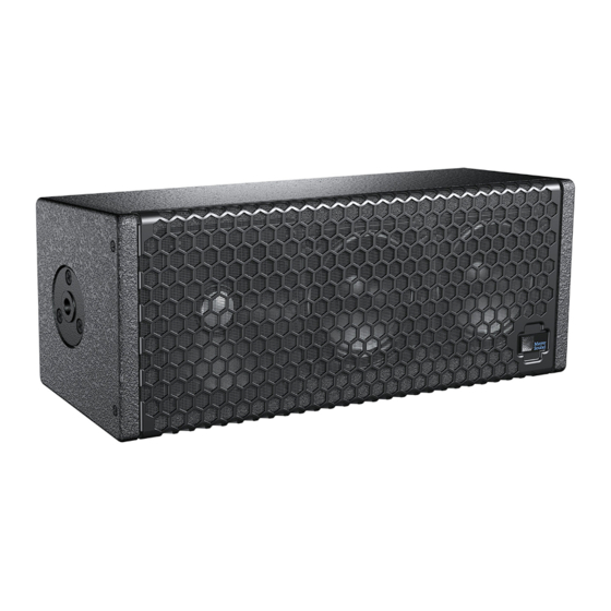
Page 7: Chapter 1: Introduction
NOTE: A note identifies an important or useful cony applications. The UP-4XP can also be paired with an piece of information relating to the topic under optional subwoofer to create a full-range system. - Page 8 CHAPTER 1: INTRODUCTION The UP-4XP is available with either a Phoenix™ 5-pin male ® multiconductor cables (such as Belden 1502 or equivalent) or sealed SwitchCraft ® EN3™ male connector for receiving allows a single cable to carry both DC power and balanced balanced audio and DC power.
-
Page 9: Product Overview
UP-4XP OPERATING INSTRUCTIONS MYA-UP4 Cradle-Style Yoke UP-4XP with MSA-UPM Pole-Mount Adapter MUB-UP4 U-Bracket in Ceiling Mount Configuration MUB-UP4 U-Bracket in Wall Mount Configuration... - Page 10 CHAPTER 1: INTRODUCTION...
-
Page 11: Chapter 2: Up-4Xp Loudspeaker
CHAPTER 2: UP-4XP LOUDSPEAKER The UP-4XP is powered by an external 48 V DC power sup- UP-4XP INPUT CONNECTOR ply, eliminating the need for wiring conduits while still pre- The UP-4XP loudspeaker is available with either a Phoenix serving the advantages of self-powered loudspeaker 5-pin male or SwitchCraft EN3 5-pin male connector for systems. -
Page 12: Up-4Xp Led
LED turns green and limiting ceases. UP-4XP LED The UP-4XP performs within its acoustical specifications at The UP-4XP has a three-color LED on its rear panel that normal temperatures when the UP-4XP LED is green, or changes color to indicate the loudspeaker’s status. -
Page 13: Up-4Xp Current Draw And Cable Requirements
Cable Lengths and Cable Gauges for UP-4XP Loudspeakers The UP-4XP turns red when the loudspeaker’s input stage Cable lengths up to 150 feet between the UP-4XP and its clips, causing the amplifier to overload. When the LED is red, the source level should be reduced. -
Page 14: Wiring Up-4Xp Loudspeaker Cables With Belden 1502 Cable (Or Equivalent)
UP-4XP loudspeakers equipped with EN3 connectors are shipped with one EN3 5-pin female-to-pigtail cable. The EN3 end of the cable connects directly to the UP-4XP input connector. The pigtail end of the cable, which connects to the loudspeaker’s external power supply, can be terminated... -
Page 15: Chapter 3: Powering Up-4Xp Loudspeakers
Phoenix 5-pin male connectors or SwitchCraft EN3 5-pin female connectors, can deliver DC power to up to eight UP-4XP loudspeakers. Cable lengths up to 150 feet for DC power are possible when using 18-AWG wire, with just 1 dB of loss in peak SPL. Longer cable runs are possible for mod- erate applications that don't drive the loudspeakers to maxi- mum output, or for installations with heavier wire gauges. - Page 16 For information on the MPS-488HP LEDs, refer to the MPS-488HP Operating Instructions. 6. Check the LEDs on the UP-4XP rear panels and verify they are green (ready to reproduce audio). MPS-488HPe 7. Enable output from the audio sources (from the mixer or processor) connected to the MPS-488HP.
-
Page 17: Connecting Up-4Xp Loudspeakers To The Mps-488 External Power Supply
The MPS-488HP external power supply power up to eight MM-4XP loudspeakers, it can only power replaces the MPS-488 model, which was origi- up to four UP-4XP loudspeakers (due to the UP-4XP’s nally designed for use with MM-4XP loudspeakers. higher power requirements and current draw). - Page 18 CHAPTER 3: POWERING UP-4XP LOUDSPEAKERS...
-
Page 19: Chapter 4: Quickfly Rigging
CHAPTER 4: QUICKFLY RIGGING The UP-4XP includes top and bottom mounting plates with POLE-MOUNTING UP-4XP LOUDSPEAKERS 3/8-16 or metric M10 threaded nuts. QuickFly mounting You can mount the UP-4XP on a third-party loudspeaker options include the MUB-UP4 U-bracket, MYA-UP4 cradle- stand with the optional MSA-UPM stand adapter style yoke, and MSA-UPM pole-mount adaptor. -
Page 20: Mya-Up4 Mounting Yoke
CHAPTER 4: QUICKFLY RIGGING MYA-UP4 MOUNTING YOKE The MYA-UP4 mounting yoke suspends a single UP-4XP loudspeaker and allows a wide range of horizontal and verti- cal adjustment. The MYA-UP4 is available in two kits: one with 3/8-16 hardware (PN 40.201.039.01), and one with M10 hardware (PN 40.201.039.02). -
Page 21: Mub-Up4 U-Bracket
The MUB-UP4 U-bracket lets you mount the UP-4XP either MUB-UP4, Ceiling-Mounted vertically or horizontally on a wall. Floor-Mounting with the MUB-UP4 The UP-4XP can be mounted on a floor or stage lip (for front-fill applications) with the MUB-UP4 U-bracket. MUB-UP4, Floor-Mounted MUB-UP4, Vertical Wall Mount... - Page 22 CHAPTER 4: QUICKFLY RIGGING...
-
Page 23: Appendix A: Up-4Xp Accessories
NOTE: The MPS-488HP external power supply replaces the MPS-488 model, which was originally designed for use with MM-4XP loudspeakers. The MPS-488 is also compatible with UP-4XP loudspeakers and can drive up to four units (using every other Channel Output). PHOENIX AND EN3 CABLE CONNECTORS AND ADAPTERS The following UP-4XP cable connectors and adapters are available from Meyer Sound. - Page 24 APPENDIX A: UP-4XP ACCESSORIES PHOENIX AND EN3 LOUDSPEAKER CABLES The following Phoenix and EN3 cables are available from Meyer Sound and can be used to connect UP-4XPs to MPS-488HPs. Phoenix and EN3 Loudspeaker Cables Part Number Cable Color Coating Length 524.014...
-
Page 25: Appendix B: Phoenix And En3 Cable Assembly
Make sure the 48 V DC from the external power supply is wired directly (and only) to the 48 V DC pins on the UP-4XP loudspeaker connector, and that the polarity is observed (negative to negative, positive to positive) to avoid damage to the loudspeaker. - Page 26 APPENDIX B: PHOENIX AND EN3 CABLE ASSEMBLY 2. If the cable has not been stripped, strip the outer shielding 1 inch and then strip the black, red, blue, and white wires .275 inch. 1” 0.275” 3. Solder the five exposed conductors to the five pins on the EN3 cord connector using the following wiring scheme. Dimple identifies Pin #1 Pin #5, White, Pin #5, White,...
- Page 27 ASSEMBLING EN3-TO-PHOENIX LOUDSPEAKER CABLES When connecting UP-4XP loudspeakers equipped with EN3 connectors to the MPS-488HPp power supply, you need an EN3 5-pin female to Phoenix 5-pin female cable. The following procedure documents how to assemble this cable. If you are starting with an EN3-to-pigtail cable, you can skip steps 4–7 in this procedure.
- Page 28 APPENDIX B: PHOENIX AND EN3 CABLE ASSEMBLY 2. Insert the five exposed conductors into the five cable holes in the Phoenix connector using the following wiring scheme. Pin #1 Black 48 V DC (–) Pin #2 48 V DC (+) Pin #3 Shield drain Audio shield...
- Page 29 Slide the boot forward so it covers the cable clamp housing completely. ASSEMBLING PHOENIX-TO-PHOENIX LOUDSPEAKER CABLES When connecting UP-4XP loudspeakers equipped with Phoenix connectors to the MPS-488HPp power supply, you need a Phoenix 5-pin female to Phoenix 5-pin female cable. The following procedure documents how to assemble this cable.
- Page 30 APPENDIX B: PHOENIX AND EN3 CABLE ASSEMBLY 2. Insert the five exposed conductors, from one end of the cable, into the five cable holes in one of the Phoenix connectors. Use the following wiring scheme. Pin #1 Black 48 V DC (–) Pin #2 48 V DC (+) Pin #3...
-
Page 31: Appendix C: Weather Protection
Installing Weather-Protected UP-4XP PROTECTION Loudspeakers A weather-protected version of the UP-4XP with a sealed The weather-protected UP-4XP can be mounted vertically or EN3 connector is available for fixed, outdoor installations. horizontally but must be mounted with a 0-degree tilt, or The weather-protected UP-4XP differs from the normal preferably with downtilt, to ensure the loudspeaker’s elec-... - Page 32 APPENDIX C: WEATHER PROTECTION...
-
Page 33: Appendix D: Up-4Xp Specifications
APPENDIX D: UP-4XP SPECIFICATIONS UP-4XP Specifications ACOUSTICAL Operating Frequency Range 66 Hz – 18 kHz Note: Recommended maximum operating frequency range. Response depends on loading condi- tions and room acoustics. Frequency Response 72 Hz – 17.5 kHz ±4 dB Note: Measured free-field with pink noise at 1 meter, 1/3rd octave resolution. - Page 34 APPENDIX D: UP-4XP SPECIFICATIONS UP-4XP Specifications Output Power 500 W total for all three channels Note: Wattage rating based on the maximum unclipped burst sine-wave rms voltage the amplifier will produce into the nominal load impedance. THD, IM TIM <.02% 4 ...
- Page 35 UP-4XP Dimensions 14.15 4.86 [359 mm] [123 mm] 6.86 5.54 4.38 [174 mm] [141 mm] [111 mm] 5.25 [133 mm] 16.52 [420 mm] 13.84 12.50 [352 mm] [317 mm] Ø0.27 (x8) 2.75 [Ø7 mm] [70 mm] UP-4XP with MUB-UP4 U-Bracket Dimensions...
- Page 36 APPENDIX D: UP-4XP SPECIFICATIONS 10.00 [254 mm] Ø0.53 [Ø13 mm] 1.00 8.63 [25 mm] [219 mm] 16.64 [423 mm] 14.86 [377 mm] 16.33 [415 mm] 6.62 [168 mm] MYA-UP4 Mounting Yoke Dimensions...
- Page 40 Meyer Sound Laboratories Inc. 2832 San Pablo Avenue Berkeley, CA 94702 www.meyersound.com © 2011 T: +1 510 486.1166 Meyer Sound. All rights reserved. F: +1 510 486.8356 UP-4XP Operating Instructions, PN 05.201.005.01 A2...
Need help?
Do you have a question about the UP-4XP and is the answer not in the manual?
Questions and answers