Table of Contents
Advertisement
Advertisement
Table of Contents

Related Manuals for Sanwa PC5000a


Summary of Contents for Sanwa PC5000a
- Page 1 PC5000a DIGITAL MULTIMETER INSTRUCTION MANUAL...
-
Page 2: Table Of Contents
CONTENTS SAFETY PRECAUTIONS Explanation of Warning Symbols Warning Instruction for Safe Use Overload protections APPLICATION AND FEATURES Applications Features NAME OF FUNCTIONS Multimeter and Test Leads Display DESCRIPTION OF FUNCTIONS Function Switch Auto Power Off Low Battery Indication Measurement Function Select Range Hold Data Hold Set Beeper Off... - Page 3 MAINTENANCE Maintenance and Inspection Calibration Battery and Fuse Replacement Storage AFTER-SALE SERVICE Warranty and Provision Repair SANWA web site SPECIFICATIONS General Specifications Measurement Range and Accuracy...
-
Page 4: Explanation Of Warning Symbols
*Before use, read the following safety precautions. This instruction manual explains how to use your new digital multimeter PC5000a safely. Before use, please read this manual thoroughly, and keep it together with the product for your reference. The instruction given under the heading "... -
Page 5: Overload Protections
17. Be sure to use a fuse of the specified rating or type. Never use a substitute of the fuse or never make a short circuit of the fuse. 18. When connecting and disconnecting the test leads, connect the ground lead (black one) first. When disconnecting them, the ground lead must be disconnected last. -
Page 6: Applications
[2] APPLICATION AND FEATURES 2-1 Applications This instrument is portable digital multimeter designed for measurement of weak current circuits. It plays an important role in circuitry analysis by using additional functions as well as measurements of small type communication equipment, electrical home appliance, lighting voltage and batteries of various type. -
Page 7: Multimeter And Test Leads
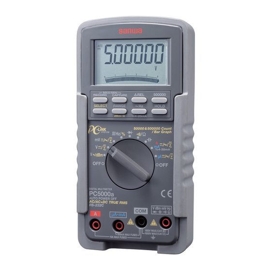
[3] NAME OF FUNCTIONS 3-1 Multimeter and Test Leads MAX/MIN LCD Display Capture button RELATIVE button MAX/MIN Recording button 500000 button SELECT button DATA HOLD button RANGE HOLD FREQUENCY button SELECT•%4-20mA SELECT button POWER Switch and FUNCTION Switch Holster mV•V•Ω• •... -
Page 8: Display
3-2 Display Display value in the main display area Auto range display : Data hold display : DC measurement display : AC measurement display Minus polarity for numeral data Battery discharge warning display Checking continuity display Relative measurement function display : Capture mode display : Record mode display MAX: Maximum value display... -
Page 9: Function Switch
[4] DESCRIPTION OF FUNCTIONS 4-1 Function Switch Turn this switch to turn on and off the power and to select the functions of "V •dBm/V /mV/ Hz •%/ /Ω• /A•mA/µA". 4-2 Auto Power Off The Auto Power Off mode turns the meter off automatically to extend battery life after approximately 17 minutes of no activities. -
Page 10: Range Hold
• In the case of Ω/ , the modes change as: Ω • In the case of µA, mA and A, the modes change as: 4-5 Range Hold Press the RANGE button momentarily to set the manual range mode then 'AUTO' disappears in the display. In manual range mode, press the button again to step through the ranges. -
Page 11: Max/Min Recording Mode
4-9 Max/Min Recording Mode Press the RECORD button momentarily to activate MAX/MIN recording mode then ' ' and 'MAX MIN' are shown. The instrument beeps when new maximum or minimum reading is updated. Press the button momentarily to read throughout the Maximum ('MAX'), Minimum ('MIN'), and Maximum minus Minimum ('MAX-MIN') readings. -
Page 12: Words
4-13 Words Analog Bargraph The analog bargraph provides a visual indication of measurement like a traditional analog meter needle. AC coupling True RMS When measurement is taken by true r.m.s., the measurement value of input signal becomes the scales of the signal power and therefore provide more effective values than those obtained by average value detection. - Page 13 Peak Average Form Factor Input Waveform Vrms Vavg Vp/Vrms Vrms/Vavg Sine Wave π Vrms π 2π π =1.414Vrms =0.707Vp =0.637Vp =1.414 =1.111 Square Wave π 2π Triangular Wave Vrms 3 π 2π =1.732Vrms =0.577Vp =0.5Vp =1.732 =1.155 Puls 2π 2π •Vp •Vp 2π...
-
Page 14: Start-Up Inspection
[5] MEASUREMENT PROCEDURE 5-1 Start-Up Inspection WARNING 1. Never use meter if the meter or test leads are damaged or broken. 2. Make sure that the test leads are not cut or otherwise damaged. START Main unit Damaged and test leads damaged? No damaged Check continuty of test... -
Page 15: Voltage Measurement
5-2 Voltage Measurement WARNING 1. Never apply an input signal exceeding the maximum rating input value. 2. Be sure to disconnect the test pins from the circuit when changing the function. 3. Always keep your fingers behind the finger guards on the probe when making measurements. - Page 16 Note: Power-up-default reference impedance will be displayed for 1 second before displaying the dBm readings. Press dBm- Ω(RANGE) button momentarily to select different reference impedance of 4, 8, 16, 32, 50, 75, 93, 110, 125, 135, 150, 200, 250, 300, 500, 600, 800, 900, 1000, up to 1200Ω. The new impedance value will be saved automatically to the non-volatile memory as power up default.
- Page 17 5-2-2 DCV / (AC+DC) V measurement 1) Applications DCV: Voltage of the battery and DC circuit are measured. (AC+DC)V: Voltage of the AC component+DC component is measured. 2) Measuring ranges 4 ranges from 5.0000V to 1000.0V 3) Measurement procedure Connect the plug of black test lead to COM terminal and plug of red test lead to V terminal.
- Page 18 5-2-3 ACmV / DCmV / (AC+DC) mV measurement 1) Applications ACmV: Voltage of the battery and DC circuit are measured. DCmV: Voltage of the DC circuit is measured. (AC+DC) mV: Voltage of the AC component+DC component is measured. 2) Measuring ranges 1 ranges 500.00mV 3) Measurement procedure Connect the plug of black test lead to COM terminal and...
-
Page 19: Line Frequency Measurement
5-3 Line Frequency Measurement WARNING 1. Never apply an input signal exceeding the maximum rating input value. 2. Be sure to disconnect the test pins from the circuit when changing the function. 3. Always keep your fingers behind the finger guards on the probe when making measurements. - Page 20 Note: Press "500000" button to between 50000 count and 500000 count. Frequency measurement is available at 'mV' or 'V' or 'µA' or 'mA' or 'A' functions. V RANGE Sensitivity (Sine RMS) Measurement Range 500mV 0.1V min 10.000Hz ~ 200.00kHz 1V min 10V min 10.000Hz ~ 100.00kHz 500V...
-
Page 21: Logic Frequency / Duty Ratio Measurement
5-4 Logic Frequency / Duty Ratio measurement WARNING 1. Never apply an input signal exceeding the maximum rating input value. 2. Be sure to disconnect the test pins from the circuit when changing the function. 3. Always keep your fingers behind the finger guards on the probe when making measurements. -
Page 22: Testing Diode/ Resistance Measurement And Checking Continuity / Capacitance Measurement
5-5 Testing Diode/ Resistance Measurement and Checking Continuity / Capacitance Measurement WARNING Never apply voltage to the input terminals. 5-5-1 Testing Diode 1) Application The quality of diodes is tested. 2) How to use Connect the plug of black test lead to COM measuring input terminal and plug of red test lead to measuring terminal. - Page 23 5-5-2 Resistance Measurement CAUTION The reading may vary because of external inductance when measuring high resistance value. 1) Applications Resistance of resistors and circuits is measured. 2) Measuring ranges 6 ranges from 500.00Ω to 50.000MΩ. 3) Measurement procedure Connect the plug of black test lead to COM input terminal and plug of red test lead to Ω...
- Page 24 5-5-3 Checking Continuity 1) Application Checking the continuity of wiring and selecting wires. 2) How to use Connect the plug of black test lead to COM measuring input terminal and plug of red test lead to measuring terminal. Set the function switch to 'Ω/ ' and select ' ' by pressing "SELECT"...
- Page 25 5-5-4 Capacitance Measurement CAUTION Discharge the capacitance before measurement. 1) Application Measures capacitance of condensor. 2) Measuring ranges 6 ranges from 50.00nF to 9999µF 3) Measurement procedure Connect the plug of black test lead to COM measuring input terminal and plug of red test lead to measuring terminal.
-
Page 26: Current / %4-20Ma Measurement
5-6 Current / %4-20mA Measurement WARNING 1. Never apply voltage to the input terminals. 2. Be sure to make a series connection via load. 3. When measuring 3-phase system, special attention should be paid to the phase-to-phase voltage which is significantly higher than the phase to earth voltage. - Page 27 3) Measurement procedure Connect the plug of black test lead to COM measuring input terminal, and plug of red test lead to A measuring terminal. Set the function switch to 'A' and select either ' ' or ' ' or ' by pressing the "SELECT"...
- Page 28 5-6-2 Current Measurement: µA, mA DCµA, mA: Maximum rating input value 500mADC ACµA, mA: Maximum rating input value 500mAAC (AC+DC) µA, mA: Maximum rating input value 500mA AC/DC 1) Applications DCA: Current in batteries and DC circuits is measured. ACA: Current in AC circuits is measured. (AC+DC)A: Current in AC component + DC component is measured.
- Page 29 Note: In %4-20mA function, it is set at 4mA = 0% and 20mA + 100%. — 26 —...
-
Page 30: How To Use Optional Products
5-7 How to use Optional Products WARNING 1. Never apply an input signal exceeding the maximum rating input value of optional products. 2. Be sure to disconnect the test pins from the circuit when changing the function. 5-7-1 Clamp probe: CL-20D 1) Applications It is suitable for measurement of alternating current in electric equipment and power supplies. - Page 31 5-7-2 Clamp probe: CL-22AD 1) Applications ACA: It is suitable for measurement of alternating current in electric equipment and power supplies. DCA: An electric current of electric circuit of a car, and a consumption electric current of direct current apparatus are measured.
- Page 32 5-7-3 Clamp probe: CL33DC 1) Applications An electric current of electric circuit of a car and a consumption electric current of direct current apparatus are measured. 2) Measuring ranges 2 ranges for 30A, 300A 3) Measurement procedure Connect the black plug to COM measuring terminal, and the red plug to V measuring terminal.
- Page 33 5-7-4 Temperature probe: T300-PC 1) Applications To measure temperature from -50 to 300 . 2) Measuring ranges Range of -50 to 30 3) Measurement procedure Connect the black plug to COM measuring terminal and the red plug to Ω measuring terminal. Set the function to 'Ω/ ' and select 'Ω' by pressing the "SELECT"...
-
Page 34: Maintenance And Inspection
[6] MAINTENANCE WARNING 1. This section is very important for safety. Read and understand the following instruction fully and maintain your instrument properly. 2. The instrument must be calibrated and inspected at least once a year to maintain the safety and accuracy. 6-1 Maintenance and Inspection 1) Appearance •... -
Page 35: Storage
Remove the battery lid screw by a screwdriver. Removed the battery lid. Take out the battery or fuse, and replace it with a new one. Attach the battery lid and fix it by the screwdriver. Battery lid screw Battery lid Rear case Fuse 12.5A/500V IR: 20kA... -
Page 36: Warranty And Provision
(1) year from the date of purchase. This warranty policy is valid within the country of purchase only, and applied only to the product purchased from Sanwa authorized agent or distributor. Sanwa reserves the right to inspect all warranty claims to determine the extent to which the warranty policy shall apply. -
Page 37: Sanwa Web Site
3) Repair after the warranty period has expired: In some cases, repair and transportation cost may become higher than the price of the product. Please contact Sanwa authorized agent / service provider in advance. The minimum retention period of service functional parts is 6 years after the discontinuation of manufacture. -
Page 38: General Specifications
[8] SPECIFICATIONS 8-1 General Specifications Display: 4-4/5 digits 50000 counts LCD display (selectable 5-4/5 digits 500000 counts for DCV and 999999 counts for Hz) Update Sampling Rate: 4-4/5 Digital data: 5 times / sec nominal 5-4/5 Digital data: 1.25 times / sec nominal 52 segments bar graph: 60 times / sec nominal Low Battery Indication: Below approx. - Page 39 Pollution degree: E.M.C.: Meets EN61326-1: 2006 Power Consumption: 42mW Typical/0.6mW Typical (Auto Power off) Dimension: 179(H) x 87(W) x 55(D) mm with holster Weight: 320 g, 460 g with holster Accessories: Test leads (TL-82), Alligator clip (CL-13), Holster (H-50), Instruction manual Optional Accessories: RS232 cable: KB-RS2 Software: PC Link, PC Link Plus...
-
Page 40: Measurement Range And Accuracy
8-2 Measurement Range and Accuracy Accuracy assurance range: 23 5 , 75%RH MAX. No condensa- tion. True RMS voltage & current accuracies are specified from 5% to 100% ofrange or otherwise specified. Maximum crest factor <5:1 at full scale & <10:1 at half scale, and with frequency components within the specified frequency bandwidth for non-sinusoidal waveforms. - Page 41 AC & AC+DC Voltage RANGE Accuracy* 45Hz - 300Hz 500.00mV, 5.0000V, 50.000V, 0.8%rdg + 60dgt 500.00V, 1000.0V 300Hz - 1kHz 500.00mV 0.8%rdg + 40dgt 5.0000V, 50.000V, 500.00V 2.0%rdg + 60dgt 1000.0V 1.0%rdg + 40dgt 1kHz - 20kHz 500.00mV 1dB** 5.0000V, 50.000V 2dB** 500.00V 3dB**...
- Page 42 DC Current RANGE Accuracy Internal Resistance 500.00µA 0.15%rdg + 20dgt Approx. 100Ω 5000.0µA 0.1%rdg + 20dgt 50.000mA 0.15%rdg + 10dgt Approx. 1Ω 500.00mA 0.1%rdg + 20dgt 5.0000A 0.5%rdg + 10dgt Approx. 0.005Ω 10.000A* 0.5%rdg + 20dgt *<6A: Continuous measurement is possible. >6A: Cool down DMM for 3 minutes after the measurement for 1 minute.
- Page 43 Ω Ohms RANGE Accuracy 500.00Ω 5.0000kΩ 0.2%rdg + 6dgt 50.000kΩ 500.00kΩ 5.0000MΩ 0.8%rdg + 6dgt 50.000MΩ 2.0%rdg + 6dgt Open Circuit Voltage : <1.3VDC (<3VDC for 500Ω range) Capacitance RANGE Accuracy* 50.00nF 0.8%rdg + 3dgt 500.0nF 5.000µF 1.0%rdg + 3dgt 50.00µF 2.0%rdg + 3dgt 500.0µF...
- Page 44 Hz Logic Level Frequency RANGE Accuracy 5.000Hz~2.0000MHz 0.002%rdg + 4dgt Sensitivity: 2.5Vp square wave %Duty Ratio RANGE Accuracy 0.1% - 99.99% 3dgt/kHz + 2dgt Input Frequency: 5Hz - 500 kHz, 5V Logic Family Diode Test Test Current Open Circuit Range Accuracy (Typical) Voltage...
- Page 45 SANWA ELECTRIC INSTRUMENT CO.,LTD. Dempa Bldg,Sotokanda2-Chome Chiyoda-Ku,Tokyo,Japan TEL: 81-3-3253-4871 /FAX: 81-3-3256-9740 Web site: http://www.sanwa-meter.co.jp E-mail: exp_sales@sanwa-meter.co.jp 07-0812 2040 6010...
Need help?
Do you have a question about the PC5000a and is the answer not in the manual?
Questions and answers