Table of Contents
Advertisement
Advertisement
Table of Contents

Related Manuals for Sanwa PC5000


Summary of Contents for Sanwa PC5000
- Page 1 PC5000 DIGITAL MULTIMETER INSTRUCTION MANUAL...
-
Page 2: Table Of Contents
CONTENTS SAFETY PRECAUTIONS Explanation of Warning Symbols Warning Instruction for Safe Use Overload protections APPLICATION AND FEATURES Applications Features NAME OF FUNCTIONS Multimeter and Test Leads Display DESCRIPTION OF FUNCTIONS Function Switch Auto Power Off Low Battery Indication Measurement Function Select Range Hold Data Hold Set Beeper Off... - Page 3 MAINTENANCE Maintenance and Inspection Calibration Battery and Fuse Replacement Storage AFTER-SALE SERVICE Repair For Information or Enquiries SPECIFICATIONS General Specifications Measurement Range and Accuracy...
-
Page 4: Explanation Of Warning Symbols
*Before use, read the following safety precautions. This instruction manual explains how to use your new digital multimeter PC5000 safely. Before use, please read this manual thoroughly. After reading it, keep it together with the product for reference to it when necessary. The instruction given under the heading "... -
Page 5: Overload Protections
15. Never use meter for measuring the line connected with equipment (i.e. motors) that generates induced or surge voltage since it may exceed the maximum allowable voltage. 16. Never use uncased meter. 17. Be sure to use a fuse of the specified rating or type. Never use a substitute of the fuse or never make a short circuit of the fuse. -
Page 6: Applications
[2] APPLICATION AND FEATURES 2-1 Applications This instrument is portable digital multimeter designed for measurement of weak current circuits. It plays an important role in circuitry analysis by using additional functions as well as measurements of small type communication equipment, electrical home appliance, lighting voltage and batteries of various type. -
Page 7: Multimeter And Test Leads
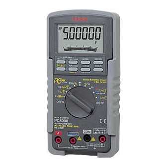
[3] NAME OF FUNCTIONS 3-1 Multimeter and Test Leads LCD Display MAX/MIN Capture button RELATIVE button MAX/MIN Recording button 500000 button DATA HOLD SELECT button button RANGE HOLD FREQUENCY button SELECT•%4-20mA SELECT button POWER Switch and FUNCTION Switch Holster mV•V•Ω• •... -
Page 8: Display
3-2 Display Display value in the main display area Auto range display : Data hold display : DC measurement display : AC measurement display Minus polarity for numeral data Battery discharge warning display Checking continuity display Relative measurement function display : Capture mode display MAX: Maximum value display MIN : Minimum value display... -
Page 9: Function Switch
[4] DESCRIPTION OF FUNCTIONS 4-1 Function Switch Turn this switch to turn on and off the power and to select the functions of "V •dBm/V /mV/ Hz•%/ /Ω• /A•mA/µA". 4-2 Auto Power Off The Auto Power Off mode turns the meter off automatically to extend battery life after approximately 17 minutes of no activities. -
Page 10: Range Hold
• In the case of Ω/ , the modes change as: Ω • In the case of µA, mA and A, the modes change as: 4-5 Range Hold Press the RANGE button momentary to set the manual range mode then 'AUTO' disappears in the display. In manual range mode, press the button again to step through the ranges. -
Page 11: Max/Min Recording Mode
4-9 Max/Min Recording Mode Press the RECORD button momentarily to activate MAX/MIN recording mode then ' ' and 'MAX MIN' are shown. The instrument beeps when new maximum or minimum reading is updated. Press the button momentarily to read throughout the Maximum ('MAX'), Minimum ('MIN'), and Maximum minus Minimum ('MAX-MIN') readings. -
Page 12: Words
4-13 Words Analog Bargraph The analog bargraph provides a visual indication of measurement like a traditional analog meter needle. AC coupling True RMS When measurement is taken by true r.m.s., the measurement value of input signal becomes the scales of the signal power and therefore provide more effective values than those obtained by average value detection. - Page 13 0 to PEAK Input waveform Vrms Vavg P/Vrms Vrms/Vavg Sine 1.414 1.000 0.900 1.414 1.111 wave Square 1.000 1.000 1.000 1.000 wave Triangular 1.732 1.000 0.866 1.732 1.155 wave Puls — — 2.000 2•D — Note: that measurement should be taken with the crest factor below NMRR (Normal Mode Rejection Ratio) NMRR is the DMM's ability to reject unwanted AC noise effect, which can cause inaccurate DC measurements.
-
Page 14: Start-Up Inspection
[5] MEASUREMENT PROCEDURE 5-1 Start-Up Inspection WARNING 1. Never use meter if the meter or test leads are damaged or broken. 2. Make sure that the test leads are not cut or otherwise damaged. START Main unit Damaged and test leads damaged? No damaged Check continuty of test... -
Page 15: Voltage Measurement
5-2 Voltage Measurement WARNING 1. Never apply an input signal exceeding the maximum rating input value. 2. Be sure to disconnect the test pins from the circuit when changing the function. 3. Always keep your fingers behind the finger guards on the probe when making measurements. - Page 16 Note: Power up default reference impedance will be displayed for 1 second before displaying the dBm readings. Press dBm- Ω(RANGE) button momentary to select different reference impedance of 4, 8, 16, 32, 50, 75, 93, 110, 125, 135, 150, 200, 250, 300, 500, 600, 800, 900, 1000, up to 1200Ω.
- Page 17 5-2-2 DCV / (AC+DC) V measurement 1) Applications DCV: Voltage of the battery and DC circuit are measured. (AC+DC)V: Voltage of the AC component+DC component is measured. 2) Measuring ranges 4 ranges from 5.0000V to 1000V 3) Measurement procedure Connect the plug of black test lead to COM terminal and plug of red test lead to V terminal.
- Page 18 5-2-3 ACmV / DCmV / (AC+DC) mV measurement 1) Applications ACmV: Voltage of the battery and DC circuit are measured. DCmV: Voltage of the DC circuit is measured. (AC+DC) mV: Voltage of the AC component+DC component is measured. 2) Measuring ranges 1 ranges 500.00mV 3) Measurement procedure Connect the plug of black test lead to COM terminal and...
-
Page 19: Line Frequency Measurement
5-3 Line Frequency Measurement WARNING 1. Never apply an input signal exceeding the maximum rating input value. 2. Be sure to disconnect the test pins from the circuit when changing the function. 3. Always keep your fingers behind the finger guards on the probe when making measurements. - Page 20 Note: Press "500000" button to toggle 50000 count and 500000 count. Frequency measurement is available at 'mV' or 'V' or 'µA' or 'mA' or 'A' functions. Range Sensitivity (Sine Wave) 500mV 0.1V 500V 100V 1000V 900V Input sensitivity varies automatically with function range selected before activating the Hz function.
-
Page 21: Logic Frequency / Duty Ratio Measurement
5-4 Logic Frequency / Duty Ratio measurement WARNING 1. Never apply an input signal exceeding the maximum rating input value. 2. Be sure to disconnect the test pins from the circuit when changing the function. 3. Always keep your fingers behind the finger guards on the probe when making measurements. -
Page 22: Testing Diode / Resistance Measurement And Checking Continuity / Capacitance Measurement
5-5 Testing Diode/ Resistance Measurement and Checking Continuity / Capacitance Measurement WARNING Never apply voltage to the input terminals. 5-5-1 Testing Diode 1) Application The quality of diodes is tested. 2) How to use Connect the plug of black test lead to COM measuring input terminal and plug of red test lead to measuring terminal. - Page 23 5-5-2 Resistance Measurement 1) Applications Resistance of resistors and circuits are measured. 2) Measuring ranges 6 ranges from 500.0Ω to 50.00MΩ. 3) Measurement procedure Connect the plug of black test lead to COM input terminal and plug of red test lead to Ω input terminal. Set the function switch at 'Ω/ ' and select 'Ω' with the "SELECT"...
- Page 24 5-5-3 Checking Continuity 1) Application Checking the continuity of wiring and selecting wires. 2) How to use Connect the plug of black test lead to COM measuring input terminal and plug of red test lead to measuring terminal. Set the function switch at 'Ω/ ' and select ' ' with the "SELECT"...
- Page 25 5-5-4 Capacitance Measurement CAUTION Discharge the capacitance before measurement. 1) Application Measures capacitance of capacitance. 2) Measuring ranges 6 ranges from 50.00nF to 9999µF 3) Measurement procedure Connect the plug of black test lead to COM measuring input terminal and plug of red test lead to measuring terminal.
-
Page 26: Current / %4-20Ma Measurement
5-6 Current / %4-20mA Measurement WARNING 1. Never apply voltage to the input terminals. 2. Be sure to make a series connection via load. 3. When measurement a 3-phase system, special attention should be taken to the phase-to-phase voltage which is significantly higher than the phase to earth voltage. - Page 27 3) Measurement procedure Connect the plug of black test lead to COM measuring input terminal and plug of red test lead to A measuring terminal. Set the function switch at 'A' and select either ' ' or ' ' or ' with the "SELECT"...
- Page 28 5-6-2 Current Measurement: µA, mA DCµA, mA: Maximum rating input value 500mADC ACµA, mA: Maximum rating input value 500mAAC (AC+DC) µA, mA: Maximum rating input value 500mA AC/DC 1) Applications DCA: Current in batteries and DC circuits is measured. ACA: Current in AC circuits is measured. (AC+DC)A: Current in AC component + DC component is measured.
- Page 29 Note: In %4-20mA function, it is set at 4mA = 0% and 20mA + 100%. — 26 —...
-
Page 30: How To Use Optional Products
5-7 How to use Optional Products WARNING 1. Never apply an input signal exceeding the maximum rating input value of optional products. 2. Be sure to disconnect the test pins from the circuit when changing the function. 5-7-1 Clamp probe: CL-20D 1) Applications It is suitable for measurement of alternating current in electric equipment and power supplies. - Page 31 5-7-2 Clamp probe: CL-22AD 1) Applications ACA: It is suitable for measurement of alternating current in electric equipment and power supplies. DCA: An electric current of electric circuit of a car and a consumption electric current of direct current apparatus are measured.
- Page 32 5-7-3 Clamp probe: CL33DC 1) Applications An electric current of electric circuit of a car and a consumption electric current of direct current apparatus are measured. 2) Measuring ranges 2 ranges for 30A, 300A 3) Measurement procedure Connect the black plug to COM measuring terminal and the red plug to mV measuring terminal.
- Page 33 5-7-4 Temperature probe: T300-PC 1) Applications It is used this product when temperature is measured to 300 from -50 2) Measuring ranges Range of -50 to 300 3) Measurement procedure Connect the black plug to COM measuring terminal and the red plug to Ω...
-
Page 34: Maintenance And Inspection
[6] MAINTENANCE WARNING 1. This section is very important for safety. Read and understand the following instruction fully and maintain your instrument properly. 2. The instrument must be calibrated and inspected at least once a year to maintain the safety and accuracy. 6-1 Maintenance and Inspection 1) Appearance •... -
Page 35: Storage
Remove the battery lid screw with a screwdriver. Removed the battery lid. Take out the battery or fuse and replace it with a new one. Attach the battery lid and fix it with the screw. Battery lid screw Battery lid Rear case Fuse 12.5A/500V Blowout capacity : 20kA... -
Page 36: Repair
[7] AFTER-SALE SERVICE 7-1 Repair If the multimeter fails during use, check the following items before sending it for repair. • Is the fuse not blown? • Is the battery not exhausted? We repair defective product at cost. When mailing it to us for repair, do not use the same cardboard box in which it was delivered to you because it may receive damage in transit. - Page 37 Power Supply: Single alkaline 9V battery; NEDA1604, IEC6LF22 or 6LR61 Sensing: AC, AC+DC True RMS Auto Power Off Timing: Idle for 17 minutes Safety: Meets the requirements for double insulation to EN61010-1 (1995), UL3111-1 (6.1944), CSA C22.2 No.1010-1-92, IEC10101-1 to terminals: /Ω•...
-
Page 38: Measurement Range And Accuracy
OVERVOLTAGE CATEGORY • Equipment of CAT is equipment for connection to circuits in which measures are taken to limit the transient overvoltages to an appropriate low level. Note: Examples include protected electronic circuits. • Equipment of CAT is energy-consuming equipment to be supplied from the fixed installation. - Page 39 AC & AC+DC Voltage RANGE Accuracy* 45Hz – 300Hz 500.00mV, 5.0000V, 50.000V, 0.8%rdg + 60dgt 500.00V, 1000.0V 300Hz – 1kHz 500.00mV 0.8%rdg + 40dgt 5.0000V, 50.000V, 500.00V 2.0%rdg + 60dgt 1000.0V 1.0%rdg + 40dgt 1kHz – 20kHz 500.00mV 1dB** 5.0000V, 50.000V 2dB** 500.00V 3dB**...
- Page 40 DC Current RANGE Accuracy Burden Voltage 500.00µA 0.15%rdg + 20dgt 0.15mV/µA 5000.0µA 0.1%rdg + 20dgt 50.000mA 0.15%rdg + 10dgt 3.3mV/mA 500.00mA 0.1%rdg + 20dgt 5.0000A 0.5%rdg + 10dgt 0.03V/A 10.000A* 0.5%rdg + 20dgt *10A continuous. AC & AC+DC Current RANGE Accuracy Burden Voltage 50Hz –...
- Page 41 Ω Ohms RANGE Accuracy 500.00Ω 5.0000kΩ 0.2%rdg + 6dgt 50.000kΩ 500.00kΩ 5.0000MΩ 0.8%rdg + 6dgt 50.000MΩ 2.0%rdg + 6dgt Open Circuit Voltage: < 1.3VDC (< 3VDC for 500Ω range) Capacitance RANGE Accuracy* 50.00nF 0.8%rdg + 3dgt 500.0nF 5.000µF 1.0%rdg + 3dgt 50.00µF 2.0%rdg + 3dgt 500.0µF...
- Page 42 %Duty Ratio RANGE Accuracy 0.1% – 99.99% 3dgt/kHz + 2dgt Input Frequency: 5Hz – 500 kHz, 5V Logic Family Diode Test Test Current Open Circuit Range Accuracy (Typical) Voltage 5.0000V 1%rdg + 1dgt 0.8mA < 3.5 VDC Audible Continuity Tester Audible threshold: between 20Ω...
- Page 43 MEMO...
- Page 44 MEMO...
- Page 45 MEMO...
- Page 46 SANWA ELECTRIC INSTRUMENT CO.,LTD. Dempa Bldg,Sotokanda2-Chome Chiyoda-Ku,Tokyo,Japan 01.02...
Need help?
Do you have a question about the PC5000 and is the answer not in the manual?
Questions and answers