Table of Contents
Advertisement
Advertisement
Table of Contents

Related Manuals for Sanwa PC500


Summary of Contents for Sanwa PC500
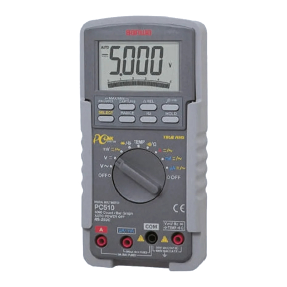
- Page 1 PC500 PC510 DIGITAL MULTIMETER INSTRUCTION MANUAL...
-
Page 2: Table Of Contents
CONTENTS SAFETY PRECAUTIONS Explanation of Warning Symbols Warning Instruction for Safe Use Overload protections APPLICATION AND FEATURES Applications Features NAME OF FUNCTIONS Multimeter and Test Leads Display DESCRIPTION OF FUNCTIONS Function Switch Auto Power Off Low Battery Indication Measurement Function Select Range Hold Data Hold Auto Lead Resistance Calibration... - Page 3 MAINTENANCE Maintenance and Inspection Calibration Battery and Fuse Replacement Storage AFTER-SALE SERVICE Warranty and Provision Repair SANWA web site SPECIFICATIONS General Specification Measurement Range and Accuracy...
-
Page 4: Safety Precautions
*Before use, read the following safety precautions. This instruction manual explains how to use your new digital multimeter PC500 and PC510 safely. Before use, please read this manual thoroughly, and keep it together with the product for your reference. The instruction given under the heading "... -
Page 5: Overload Protections
16. Never use uncased meter. 17. Be sure to use a fuse of the specified rating or type. Never use a substitute of the fuse or never make a short circuit of the fuse. 18. When connecting and disconnecting the test leads, connect the ground lead (black one) first. -
Page 6: Application And Features
2-2 Features <PC500 / PC510> The instrument meets the requirements to Safety Standard IEC61010. The main unit case and the circuit board are made of fire retarding materials. -
Page 7: Name Of Functions
[3] NAME OF FUNCTIONS 3-1 Multimeter and Test Leads LCD Display MAX/MIN Capture button RELATIVE button MAX/MIN Recording button Zoom Analog Bargraph button DATA HOLD SELECT button button RANGE HOLD FREQUENCY button SELECT button Holster POWER Switch and FUNCTION Switch V•mV•Hz•... -
Page 8: Display
3-2 Display Display value in the main display area Auto range display : Data hold display : Capture mode display : DC measurement display : AC measurement display Minus polarity for numeral data Testing diode display Battery discharge warring display Zoom analog bargraph display Relative measurement function display Analog bargraph... -
Page 9: Description Of Functions
[4] DESCRIPTION OF FUNCTIONS 4-1 Function Switch Turn this switch to turn on and off the power and to select the functions of "V /mV/ • /Temp(PC510)/Ω• /A/mA/µA". 4-2 Auto Power Off The Auto Power Off mode turns the meter off automatically to extend battery life after approximately 17 minutes of no activities. -
Page 10: Range Hold
4-5 Range Hold Press the RANGE button momentarily to set the manual range mode then 'AUTO' disappears in the display. In manual range mode, press the button again to step through the ranges. To return to the auto mode, press the button for 1 sec. or more then AUTO is shown. -
Page 11: Set Beeper Off
4-8 Set Beeper Off Press the Hz button while turning the function switch on to disable the Beeper feature. 4-9 RS232C Interface The instrument equips with an optical isolated interface port at the back of meter body for data communication. Optional accessories KB-RS2 (RS232 cable), KB-USB2(USB cable) and PC Link or PC Link Plus (software), are required for Data logging system. -
Page 12: Max/Min Capture Mode (Peak Hold): Pc510
The analog bargraph provides a visual indication of measurement like a traditional analog meter needle. AC Sensing PC500: Average RMS When measurement is taken by "average r.m.s.", no error is caused as the input signal is shine wave with no distortion. However, if the input waveform is distorted sine cave or non-sinusoidal wave, conversion to root-mean-square values is very difficult, resulting in a large error. - Page 13 PC510: AC coupling True RMS When measurement is taken by true r.m.s., the measurement value of input signal becomes the scales of the signal power and therefore provide more effective values than those obtained by average value detection. This multimeter imploys this true RMS circuit, which enables measurement of sine wave and non-sinusoidal waves like square wave and triangular wave in r.m.s.
- Page 14 NMRR (Normal Mode Rejection Ratio) NMRR is the DMM's ability to reject unwanted AC noise effect, which causes inaccurate DC measurements. NMRR is typically specified in terms of dB (decibel). This series has a NMRR specification of >60dB at 50 and 60Hz, which means a good ability to reject the effect of AC noise in DC measurements.
-
Page 15: Measurement Procedure
[5] MEASUREMENT PROCEDURE 5-1 Start-Up Inspection WARNING 1. Never use meter if the meter or test leads are damaged or broken. 2. Make sure that the test leads are not cut or otherwise damaged. START Main unit Damaged and test leads damaged? No damaged Check continuty of test... -
Page 16: Voltage Measurement
5-2 Voltage Measurement WARNING 1. Never apply an input signal exceeding the maximum rating input value. 2. Be sure to disconnect the test pins from the circuit when changing the function. 3. Always keep your fingers behind the finger guards on the probe when making measurements. -
Page 17: Frequency Measurement
5-3 Frequency Measurement WARNING 1. Never apply an input signal exceeding the maximum rating input value. 2. Be sure to disconnect the test pins from the circuit when changing the function. 3. Always keep your fingers behind the finger guards on the probe when making measurements. - Page 18 Note: Frequency measurement is available at temp/mA/Ω/ functions. Range Sensitivity (Sine Wave) Range 500mV 300mV 10Hz - 125kHz 10Hz - 125kHz 10Hz - 20kHz 500V 10Hz - 1kHz 1000V 300V 10Hz - 1kHz Ω/ 300mV 10Hz - 125kHz µA/mA, A 10% F.S.
-
Page 19: Temperature Measurement:pc510
5-4 Temperature Measurement: PC510 1) Application Temperature is measured. 2) Measuring ranges Range from -50 to 1000 3) Measurement procedure Input the -plug to COM input terminal and the +plug to Temp terminal. Set the function switch to 'Temp' and select either ' ' or ' ' by pressing the SELECT switch. -
Page 20: Capacitance Measurement And Testing Diode/Resistance Measurement And Checking Continuity
' and select ' ' by pressing the SELECT button. (For PC510) ; Set the function switch to '. (For PC500) Apply the red and black test pins to an object to measure. Read the value on the display. After measurement, release the red and black test pins from the object measured. - Page 21 ' and select ' ' with the SELECT switch. (For PC510) ; Set the function switch at '. (For PC500) Apply the black test pins to the cathode of the diode and the red test pin to the anode. Check reading for judgment of good or defective.
- Page 22 5-5-3 Resistance Measurement 1) Applications Resistance of resistors and circuits is measured. 2) Measuring ranges 7 ranges from 50.00Ω to 50.00MΩ. 3) Measurement procedure Connect the plug of black test lead to COM input terminal and plug of red test lead to Ω input terminal. Set the function switch to 'Ω/ ' and select 'Ω' by pressing the SELECT button.
- Page 23 5-5-4 Checking Continuity 1) Application Checking the continuity of wiring and selecting wires. 2) How to use Connect the plug of black test lead to COM measuring input terminal and plug of red test lead to measuring terminal. Set the function switch to 'Ω/ and select ' ' by pressing SELECT button.
-
Page 24: Current Measurement
5-6 Current Measurement WARNING 1. Never apply voltage to the input terminals. 2. Be sure to make a series connection via load. 3. When measuring 3-phase system, special attention should be paid to the phase-to-phase voltage which is significantly higher than the phase to earth voltage. 4. - Page 25 3) Measurement procedure Connect the plug of black test lead to COM measuring input terminal and plug of red test lead to A measuring terminal. Set the function switch at 'A' and select either ' ' or ' with the SELECT button. In the circuit to measure and apply the red and black test pins in series with load.
- Page 26 5-6-2 Current Measurement: µA, mA DCµA, mA: Maximum rating input value 500mADC ACµA, mA: Maximum rating input value 500mAAC 1) Applications DCA: Current in batteries and DC circuits is measured. ACA: Current in AC circuits is measured. 2) Measuring ranges 4 ranges for 400.0µA/4000µA and 40.00mA/400.0mA 3) Measurement procedure Connect the plug of black test lead to COM measuring input...
-
Page 27: How To Use Optional Product
5-7 How to use Optional Product WARNING 1. Never apply an input signal exceeding the maximum rating input value of optional products. 2. Be sure to disconnect the test pins from the circuit when changing the function. 5-7-1 Clamp probe: CL-20D 1) Applications It is suitable for measurement of alternating current in electric equipment and power supplies. - Page 28 5-7-2 Clamp probe: CL-22AD 1) Applications ACA: It is suitable for measurement of alternating current in electric equipment and power supplies. DCA: An electric current of electric circuit of a car, and a consumption electric current of direct current apparatus are measured.
- Page 29 5-7-3 Clamp probe: CL33DC 1) Applications An electric current of electric circuit of a car and a consumption electric current of direct current apparatus are measured. 2) Measuring ranges 2 ranges for 30A, 300A 3) Measurement procedure Connect the black plug to COM measuring terminal, and the red plug to mV measuring terminal.
- Page 30 5-7-4 Temperature probe: T300-PC 1) Applications To measure temperature from -50 to 300 2) Measuring ranges Range of -50 to 300 3) Measurement procedure Connect the black plug to COM measuring terminal and the red plug to Ω measuring terminal. Set the function to 'Ω/ ' and select 'Ω' by pressing the “SELECT”...
-
Page 31: Maintenance And Inspection
[6] MAINTENANCE WARNING 1. This section is very important for safety. Read and understand the following instruction fully and maintain your instrument properly. 2. The instrument must be calibrated and inspected at least once a year to maintain the safety and accuracy. 6-1 Maintenance and Inspection 1) Appearance •... -
Page 32: Storage
Remove the battery lid screw with a screwdriver. Removed the battery lid. Take out the battery or fuse and replace it with a new one. Attach the battery lid and fix it with the screw. Battery lid screw Battery lid Rear case Fuse 12.5A/500V IR: 20kA... -
Page 33: Warranty And Provision
(1) year from the date of purchase. This warranty policy is valid within the country of purchase only, and applied only to the product purchased from Sanwa authorized agent or distributor. Sanwa reserves the right to inspect all warranty claims to determine the extent to which the warranty policy shall apply. -
Page 34: Sanwa Web Site
3) Repair after the warranty period has expired: In some cases, repair and transportation cost may become higher than the price of the product. Please contact Sanwa authorized agent / service provider in advance. The minimum retention period of service functional parts is 6 years after the discontinuation of manufacture. -
Page 35: General Specification
Nominal 0.15x(specified accuracy)/ or 28 or otherwise specified Power Supply: 9V battery; NEDA1604A, JIS006P or IEC6F22 Sensing: True RMS for PC510, Average sensing for PC500 Auto Power Off Timing: Idle for 17 minutes Safety: IEC61010-1 (EN61010-1) 2nd (2001) /Ω• /Hz : CAT for 600V DC &... - Page 36 Power Consumption: 2.6mA Typical Dimension: 179(H) x 87(W) x 55(D) mm with holster Weight: 320 mg, 460 mg with holster Accessories: Test leads (TL-82), Holster (H-50), Battery (installed), Instruction manual, K-type thermocouple (K-250PC) for only PC510. Optional Accessories: RS232 cable: KB-RS2, USB cable : KB-USB2 Software: PC Link, PC Link Plus K-type adapter: K-AD for PC510 Temperature Probe: T-300PC (Platinic thin film)
-
Page 37: Measurement Range And Accuracy
OVERVOLTAGE CATEGORY • Equipment of CAT is equipment for connection to circuits in which measures are taken to limit the transient overvoltages to an appropriate low level. Note: Examples include protected electronic circuits. • Equipment of CAT is energy-consuming equipment to be supplied from the fixed installation. - Page 38 AC Voltage RANGE Accuracy 50Hz - 60Hz 50.00mV, 500.0mV, 5.000V, 0.5% rdg + 3dgt 50.00V, 500.0V, 1000V 40Hz - 500Hz 50.00mV, 500.0mV 0.8% rdg + 3dgt 5.000V, 50.00V, 500.0V 1.0% rdg + 4dgt 1000V 1.2% rdg + 4dgt Up to 20kHz 50.00mV, 500.0mV 0.5dB** 5.000V, 50.00V, 500.0V...
- Page 39 AC Current RANGE Accuracy Burden Voltage 50Hz - 60Hz 500.0µA 0.15mV/µA 5000µA 0.6% rdg +3dgt 0.15mV/µA 50.00mA 3.3mV/mA 500.0mA 1.0% rdg +3dgt 3.3mV/mA 5.000A 0.03V/A 0.6% rdg +3dgt 10.00A* 0.03V/A 40Hz - 1kHz 500.0µA 0.15mV/µA 5000µA 0.8% rdg +4dgt 0.15mV/µA 50.00mA 3.3mV/mA 500.0mA...
- Page 40 Hz Frequency Function Sensitivity (Sine RMS) Range 300mV 10Hz - 125kHz 10Hz - 125kHz 10Hz - 20kHz 500V 10Hz - 1kHz 1000V 300V 10Hz - 1kHz Ω, 300mV 10Hz - 125kHz µA, mA, A 10% F.S. 10Hz - 125kHz Accuracy: 0.01% rdg + 2dgt Capacitance RANGE Accuracy*...
- Page 41 Do not use the tester near places where strong electromagnetic waves and trance are generated or strong electrical voltages are generated. Specifications and external appearance of the product described above may be revised for modification without prior notice. — 38 —...
- Page 42 SANWA ELECTRIC INSTRUMENT CO.,LTD. Dempa Bldg,Sotokanda2-Chome Chiyoda-Ku,Tokyo,Japan 06.05...
Need help?
Do you have a question about the PC500 and is the answer not in the manual?
Questions and answers