Computherm Q3 Operating Instructions Manual
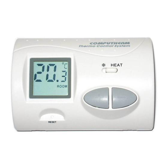
Computherm q3 digital room thermostat
Hide thumbs
Also See for Q3:
- Operating instructions manual (17 pages) ,
- Operating instructions manual (24 pages)
Advertisement
Table of Contents
- 1 General Description of the Thermostat
- 2 Location of the Device
- 3 Installation of the Thermostat
- 4 Putting the Thermostat into Operation
- 5 Basic Settings
- 6 Selecting the Switching Sensitivity (Accuracy)
- 7 Switching between the Heating and Cooling Mode
- 8 Selecting the Displayed Temperature
- 9 Setting the Desired Temperature
- 10 Operation of the Installed Thermostat
- 11 Economy Mode
- 12 Comfort Mode
- 13 Battery Replacement
- 14 Technical Data
- Download this manual
Advertisement
Table of Contents

Related Manuals for Computherm Q3


Summary of Contents for Computherm Q3
- Page 1 Edited by Foxit PDF Editor COMPUTHERM Q3 Copyright (c) by Foxit Software Comp For Evaluation Only. digital room thermostat software! Operating Instructions...
- Page 2 GENERAL DESCRIPTION OF THE THERMOSTAT COMPUTHERM Q3 type switched-mode room thermostat is suitable to regulate the overwhelming majority of boilers and air conditioners available in Hungary. It can easily be connected to any gas boiler or air conditioning device that has a double wire connector for a room thermostat, regardless of whether it has a 24V or 230V control circuit.
- Page 3 The switching sensitivity of the thermostat can be set to ±0.1°C or ±0.2°C (default setting). This means the difference between the ad- justed temperature and the actual tem- The information shown on the liquid crystal display of the thermostat perature measured includes the following: during the switch- process.
- Page 4 es the boiler on at 19.8°C or below, and switches it off at 20.2°C or above. Please refer to Section 4.1 for the modification of the factory default switching sensitivity of ±0.2°C. 1. LOCATION OF THE DEVICE It is reasonable to locate it in a room used regularly or for many hours per day so that it is in the direction of natural ventilation in the room but protected from drought or extreme heat (e.g.
- Page 5 the radiator valve with a manual control knob in the room where the room thermostat is to be located, otherwise the thermostatic head may disturb the temperature control of the flat. 2. INSTALLATION OF THE THERMOSTAT • To install the thermostat, detach the rear panel of the thermostat from the front panel by loosening the screws at the bottom of the cover as shown in the...
- Page 6 • Using a small screwdriver, remove the cover of the terminal block from the inner side of the rear panel. The thermostat controls the boiler or air conditioner through a potential-free alternating relay that has the following connection points: No. 1 (NO); No. 2 (COM) and No.
- Page 7 To prevent electric shock, replace the inner cover removed for the connection of wires after the assembling process has been completed. ATTeNTION! Always consider the loadability of the thermostat and follow the manufacturer’s instructions of the heating or cooling equipment. The device must be installed and connected by a qualified professional.
-
Page 8: Basic Settings
with the diagram in the battery compartment. After the batteries have been inserted, the display flashes the measured room temperature. (If this information fails to appear on the display, press the “RESET” button with a wooden or plastic stick. To press the button, do not use any electrically conductive materials, e.g. - Page 9 4.1 Selecting the Switching Sensitivity (Accuracy) The switching sensitivity of the thermostat can be selected or adjusted by the uppermost jumper. With factory default settings the jumper is located on the central and right pins, resulting in a switching sensitivity of ±0.2°C. It can be modified to ±0.1°C by relocating the jumper onto the left and central pins.
- Page 10 switches of the boiler reduce its efficiency and hence increases the gas consumption. We recommend using the ±0.1°C switching sensitivity for heating systems with high thermal inertia (e.g. underfloor heating), and the ±0.2°C switching sensitivity (factory default setting) for heating systems with low thermal inertia (e.g. flat panel radiators).
- Page 11 are closed above the set temperature in cooling mode (taking the switching sensitivity into account). The closed state of the output terminals No. 1 and No. 2 are indicated by the notice “HEAT” (heating) or “A/C” (cooling) in the bottom left corner of the display, according to the selected mode.
- Page 12 and central pins the displayed temperature can be modified so that the display alternately shows the current room temperature and the adjusted temperature for 4 seconds, respectively. In this mode, the notices “ROOM” and “SET” are alternately shown under the currently displayed temperature in the bottom right corner of the display, indicating whether the display shows the room temperature or the adjusted temperature value.
- Page 13 5. SETTING THE DESIRED TEMPERATURE After putting the thermostat into operation and adjusting the basic settings the thermostat is ready for operation and the adjustment of the temperature can be started. Above the temperature adjustment buttons ( ) a switch is located. For both the economy ( w ) and the comfort ( ☼...
- Page 14 keeping a flat warn requires more energy than heating it up. (When using a stove, more gas is needed to keep a pan of water boiling than to just keep it warm.) The factory default temperature is 18°C for the economy position and 20°C for the comfort position.
- Page 15 repeatedly or continuously (the change in values is accelerated), the desired temperature to be maintained at the place where the thermostat has been installed can be set in steps of 0.5°C. • Approximately 7 seconds after setting the room temperature to be maintained, the device automatically switches to normal mode.
- Page 16 6. OPERATION OF THE INSTALLED THERMOSTAT After setting the economy and comfort temperatures, the temperature needed at the moment can be selected using the switch. 6.1 Economy Mode ( w ) (left hand position of the switch) In the left hand position of the switch, the thermostat provides the set economy temperature (e.g.
- Page 17 connected to the thermostat is switched on. The appearance of the notice “HEAT” (heating) or “A/C” (cooling) in the bottom left corner of the display indicates that the device is activated, according to the heating or cooling mode, respectively. 6.2 Comfort Mode ( ☼ ) (right hand position of the switch) In the right hand position of the switch, the thermostat provides the set comfort temperature (e.g.
-
Page 18: Battery Replacement
notice “HEAT” (heating) or “A/C” (cooling) in the bottom left corner of the display indicates that the device is activated, according to the heating or cooling mode, respectively. 7. BATTERY REPLACEMENT The average lifetime of the batteries is 1 year. The icon alternately replacing the temperature value on the display indicates low battery voltage. -
Page 19: Technical Data
TECHNICAL DATA — switchable voltage: 24V AC/DC to 250V AC, 50 Hz — switchable current: 8A (2A inductive load) — temperature measurement range: 5 to 35°C (in 0.1°C increments) — adjustable temperature range: 5 to 35°C (in 0.5°C increments) — temperature measurement accuracy: ±0.5°C —...
Need help?
Do you have a question about the Q3 and is the answer not in the manual?
Questions and answers