
Related Manuals for Thermal Arc Raider 10,000 Pro K


Summary of Contents for Thermal Arc Raider 10,000 Pro K
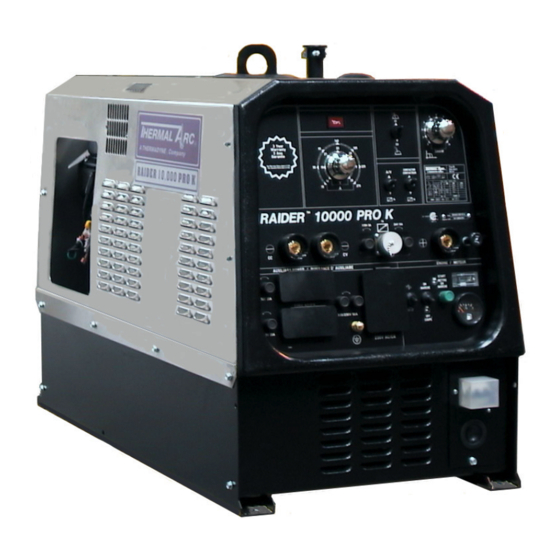
- Page 1 Raider 10,000 Pro K DC CC/CV Welding Generator STICK AUXILIARY POWER Owners Manual MI420-06-00-00 Date 06/03/04 KLA Manual...
- Page 2 Manual Date 06/03/04 KLA...
-
Page 3: Table Of Contents
Table of Contents Statement of Warranty .................................5 SECTION 1: GENERAL INFORMATION ..........................6 1.01 Notes, Cautions and Warnings ............................6 1.02 Important Safety Precautions ............................6 1.03 Publications..................................7 1.04 Note, Attention et Avertissement ............................8 1.05 Precautions De Securite Importantes ..........................8 1.06 Documents De Reference..............................10 SECTION 2: TECHNICAL SPECIFICATIONS........................13 2.01 Specifications .................................13 2.02 Volt-Amp Curve ................................14... - Page 4 Proposition 65 WARNING: This product, when used for welding or cutting, produces fumes or gases which contain chemicals known to the State of California to cause birth defects and, in some cases, cancer. (California Health & Safety Code Sec.25249.5 et seq.) Date 06/03/04 KLA Manual...
-
Page 5: Statement Of Warranty
Thermal Arc with respect to any contract, or anything done in connection therewith such as the performance or breach thereof, or from the manufacture, sale, delivery, resale, or use of any goods covered by or furnished by Thermal Arc whether arising out of contract, negligence, strict tort, or under any warranty, or otherwise, shall not, except as expressly provided herein, exceed the price of the goods upon which such liability is based. -
Page 6: Section 1: General Information
• Keep all fumes and gases from the breathing SECTION 1: GENERAL area. Keep your head out of the welding fume INFORMATION plume. • Use an air-supplied respirator if ventilation is 1.01 Notes, Cautions and not adequate to remove all fumes and gases. Warnings •... -
Page 7: Publications
• Install and maintain equipment according to ARC WELDING RAYS NEC code, refer to item 4 in Subsection 1.03, Arc Welding/Cutting Rays can injure your eyes and Publications. burn your skin. The arc welding/cutting process • Disconnect power source before performing any produces very bright ultra violet and infra red light. -
Page 8: Note, Attention Et Avertissement
Standards Institute, 1430 Broadway, New York, des informations à caractère important. Ces mises en NY 10018 relief sont classifiées comme suit : 7. AWS Standard A6.0, WELDING AND CUTTING NOTE CONTAINERS WHICH HAVE HELD COMBUSTIBLES, obtainable from American Toute opération, procédure ou renseignement Welding Society, 550 N.W. - Page 9 • Utilisez un appareil respiratoire à alimentation • Prenez des soins particuliers lorsque la zone de en air si l’aération fournie ne permet pas travail est humide ou moite. d’éliminer la fumée et les gaz. • Montez et maintenez le matériel conformément •...
-
Page 10: Documents De Reference
autre sorte de protection oculaire. Documents, U.S. Government Printing Office, Washington, D.C. 20402 • Portez des gants de soudeur et un vêtement protecteur approprié pour protéger votre peau 2. Norme ANSI Z49.1, LA SÉCURITÉ DES contre les étincelles et les rayons de l’arc. OPÉRATIONS DE COUPE ET DE SOUDAGE, disponible auprès de la Société... - Page 11 Brochure GCA P-1, LA MANIPULATION SANS RISQUE DES GAZ COMPRIMÉS EN CYLINDRES, disponible auprès l’Association Comprimés (Compressed Gas Association), 1235 Jefferson Davis Highway, Suite 501, Arlington, VA 22202 12. Norme CSA W117.2, CODE DE SÉCURITÉ POUR SOUDAGE COUPE, disponible auprès de l’Association des Normes Canadiennes, Standards Sales, 178 Rexdale Boulevard, Rexdale, Ontario, Canada, M9W 13.
-
Page 12: Section 2: Technical Specifications
SECTION 2: TECHNICAL SPECIFICATIONS 2.01 Specifications The Thermal Arc Raider 10,000 Pro K is a gasoline engine driven DC welding generator with selectable Constant Current (CC) and Constant Voltage (CV) output characteristics. This unit is designed for use with Shielded Metal Arc Welding (SMAW), Gas Metal Arc Welding (GMAW), and GAS Tungsten Arc Welding - (GTAW) processes. -
Page 13: Volt-Amp Curve
2.02 Volt-Amp Curve 2.04 Front Panel Descriptions 3 Year Warranty 3 Ans SMAW Garantie See Warranty P olicy dated 4/1/02 V oir Garantie Police date 4/1/02 CONTACTOR CONTACTEUR RAIDER 10000 PRO K 115V 3A 24V 10A AUXILIARY POWER / PUISSANCE D' AUXILIAIRE ENGINE / MOTEUR START... -
Page 14: Dimensions And Weight
11. Remote AMPERAGE / VOLTAGE Switch – Allows 2.05 Dimensions and Weight remote amperage/voltage device operation through the 14 pin receptacle. 12. Process Selector switch : CC/CV – Allows the Height 710mm 27.9” operator to select the CC (Constant Current) process Width 530mm 20.86”... -
Page 15: Installing Welding Generator
2.07 Installing Welding 2.09 Air Flow Clearance Generator Lifting forks. Lifting Eye. Use lifting eye or lifting forks to move unit. If using lifting forks, extend forks beyond opposite side of unit. Trailer - Install unit on trailer according to trailer manufacturing. -
Page 16: Generator Auxiliary Power System
460 Three Phase connection WARNING: ENGINE FUEL CAN CAUSE FIRE OR (1) 460 V 13 A AC three phase Circuit Breaker EXPLOSION. connection. Supplies 60 Hz three-phase power at maximum speed (3600 rpm). Maximum output is 10 kVA/kW. • Stop engine before fueling. •... -
Page 17: Wiring Optional 230 Volt Plug
2.11 Wiring Optional 230 2.12 Grounding The Volt Plug Generator The plug can be wired for a 230V, 2-wire load or a 115/230V, 3-wire load. See diagram below TO A TRUCK OR TRAILER FRAME Generator base. White - Neutral terminal. Metal vehicle frame. -
Page 18: When Connecting To Home, Shop, Or Farm Wiring
2.13 When Connecting To NOTE: It is the installer's responsibility to follow the applicable rules from the National Electrical Code Home, Shop, or Farm (NEC), state, local, and OSHA codes for the installation and use of auxiliary power generators. Wiring NOTE: THIS UNIT SHOULD NEVER BE USED AS THE MAIN SOURCE OF POWER. -
Page 19: Technical Specifications
local personnel and follow all applicable codes for safe and proper installation. Motor-starting Requirements Starting amperage requirements are many times the Before the generator may be used to supply power, the running amperage of the motor. Starting requirements installer must first become familiar with and meet all must be determined to assure that the generator is capable codes applicable to the installation of an auxiliary of starting the motor without damaging it. -
Page 20: Simultaneous Welding And Power
2.15 Simultaneous Welding WELD CABLE CONNECTIONS 1. Do not touch live electrical parts. 2. Shut down unit before making any weld output and Power connections. 3. Do not change position of the welding cable connectors while welding Weld Total 120 volt 240 volt 460 volt 4. - Page 21 GAS METAL ARC WELDING (GMAW) Install and connect unit according to the Installation section. Install and connect wire feed system according to wire feeder installation guide. Wear gloves, welding helmet and protective clothing. Connect work lead to the negative CV terminal. Place the process selector switch in CV position.
-
Page 22: Section 3: Trouble Shooting Guide
SECTION 3: TROUBLE SHOOTING GUIDE The Raider 10,000 Pro K is an asynchronous (brush-less) style generator. The basic theory of this style generator is as follows: A permanent magnet (rotor) is rotating at a high speed inside a winding wrapped around a laminated steel core (stator). This produces a small voltage at a very low intensity, 1 to 2 volts at 1 amp in the exciter windings. -
Page 23: There Is No Auxiliary Voltage And/Or Welding Current
3.01 There is No Auxiliary Voltage and/or Welding Current In examining this particular fault it must be remembered that an asynchronous generator with excitation by capacitors has the characteristic of becoming automatically de-energized while it is functioning (no longer supplies current). Also an asynchronous generator will not self-excite when it is started up if there is a short-circuit whether outside of the generator (in the user circuit) or inside it (in the windings and in the control equipment). -
Page 24: Excessive Fall Of Voltage When The Load Is Connected
3.03 Excessive Fall of Voltage When The Load is Connected PROBABLE CAUSE CONTROLS REMEDIES The engine does not maintain the Check whether the fine current Replace or repair Fine Current nominal speed. control is functioning. control assembly. Check engine fuel system. Refer to Engine manual for testing fuel system. -
Page 25: Section 5 Parts List
Section 5 Parts List 5.01 Stator Parts... - Page 26 Item Part Number Description 11-4031 Ring 11-3283 11-4177 O-ring 11-3077 Seeger ring 11-3078 Bearing 11-4188 Rotor tie-rod 11-3308 Flange with bearing seat 11-3954 Stator 11-3597 Hook 11-3281 Rotor 11-3307 Tie rod 11-3873 Engine bulkhead 11-3793 Silencer 11-4185 5A fuse 11-4179 Fuse holder 11-3499 Flap...
-
Page 27: Front Panel Parts
5.02 Front Panel Parts... - Page 28 Item Part Number Description 11-3779 13A 3 poles circuit breaker 11-3143 3 poles circuit breaker cover 11-3138 Cable holder 11-3245 Circuit breaker support 11-3510 Protection cover 11-3087 Rubber wire holder 11-3936 Earth clamp 11-3810 O-ring 11-3150 Fuel gauge – Monitor fuel level 11-4133 230V 50A 14-50 single phase outlet 11-3789...
-
Page 29: Sheet Metal Parts
5.03 Sheet Metal Parts... - Page 30 Item Part Number Description 11-4082 Frame 11-4186 Canopy 11-3610 Hook gasket 11-3611 Fuel tank cap gasket 11-3612 Fuel tank cap 11-4190 15VA 100HZ Transformer 11-3614 3 poles terminal board 11-3332 GS9705 electronic panel 11-3331 P02041 electronic panel 11-4126 Electronic panel support 11-4084 Panel 11-4164...
-
Page 31: Common Engine Part Numbers
5.05 Common Engine Part Numbers Engine Type COMMAND CH20 KOHLER suggested replacement Engine type COMMAND CH20 with the following Item KOHLER differences. Part Number Oil Filter 12 050 01-S Key type Starting box Air Filter Element 47 083 03-S Generator style choke Precleaner 24 083 02-S Fuel Filter... -
Page 32: Schematic
5.06 Schematic... -
Page 33: Pin Receptacle Signals
5.07 14 pin Receptacle Signals Socket Pin Function 24VAC auxiliary high side. Input to energize solid state contator (Contact closure between pin A and pin B) 5k ohm (maximum) connection to 5k ohm remote control potentiometer Zero ohm (minimum) connection to 5k ohm remote control potentiometer Wiper arm connection to 5k ohm remote control potentiometer Not Used 24/115 VAC circuit common, also connected to chassis...
Need help?
Do you have a question about the Raider 10,000 Pro K and is the answer not in the manual?
Questions and answers
What do I get my coils at on the raider 10,000 pro
What is the gap between my coil and magneto supposed to be at