
Related Manuals for Thermal Arc ARC MASTER 175 TE


Summary of Contents for Thermal Arc ARC MASTER 175 TE
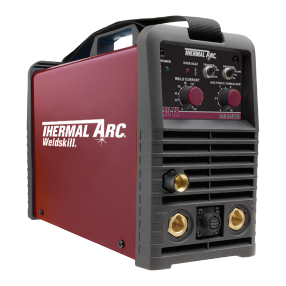
- Page 1 175 TE ARC MASTER ® InvERTER ARC WEldER Art # A-08667 Operating Manual Revision: AC Issue Date: December 20, 2010 Manual No.: 0-5116 Operating Features:...
- Page 2 YOU ARE IN GOOD COMPANY! The Brand of Choice for Contractors and Fabricators Worldwide. Thermal Arc is a Global Brand of Arc Welding Products for Thermadyne Industries Inc. We manufacture and supply to major welding industry sectors worldwide including; Manufacturing, Construction, Mining, Automotive, Aerospace, Engineering, Rural and DIY/Hobbyist.
- Page 3 While the information contained in this manual represents the Manufacturer’s best judgement, the Manufacturer assumes no liability for its use. Operating Manual Number 0-5116 for: Arc Master 175 TE TIG/STICK Package System Part No. W1003003 Arc Master 175 TE Power Source Part No.
-
Page 4: Table Of Contents
TABLE OF CONTENTS SECTION 1:SAFETY INSTRUCTIONS AND WARNINGS ..........1-1 1.01 Arc Welding Hazards ..................1-1 1.02 Principal Safety Standards ................1-4 1.03 Symbol Chart ....................1-5 1.04 Precautions De Securite En Soudage A L’arc ..........1-6 1.05 Dangers relatifs au soudage à l’arc ..............1-6 1.06 Principales Normes De Securite .............. - Page 5 TABLE OF CONTENTS SECTION 4:OPERATION ................... 4-1 4.01 General Safety Precautions ................4-1 4.02 Overview ......................4-1 4.03 Front Panel ..................... 4-2 4.04 SMAW Electrode Polarity ................4-4 4.05 Effects of Stick Welding Various Materials ............4-4 4.06 GTAW Electrode Polarity ................. 4-5 4.07 Guide for Selecting Filler Wire ................
-
Page 7: Section 1:Safety Instructions And Warnings
safety instruction arc master 175te SECTION 1: SAFETY INSTRUCTIONS AND WARNINGS WARNING PROTECT YOURSELF AND OTHERS FROM POSSIBLE SERIOUS INJURY OR DEATH. KEEP CHILDREN AWAY. PACEMAKER WEARERS KEEP AWAY UNTIL CONSULTING YOUR DOCTOR. DO NOT LOSE THESE INSTRUCTIONS. READ OPERATING/INSTRUCTION MANUAL BEFORE INSTALLING, OPERATING OR SERVICING THIS EQUIPMENT. -
Page 8: Safety Instructions
175 te safety instructions WARNING WARNING WELDING can cause fire or explosion. FUMES AND GASES can be hazardous to your health. Sparks and spatter fly off from the welding arc. The flying sparks and hot metal, weld spatter, hot Welding produces fumes and gases. - Page 9 safety instruction arc master 175te 10. Remove stick electrode from holder or cut off welding wire at contact tip when not in use. WARNING ENGINE FUEL can cause fire or explosion. WARNING Engine fuel is highly flammable. FLYING SPARKS AND HOT METAL can cause 1.
-
Page 10: Principal Safety Standards
175 te safety instructions 1.02 Principal Safety Standards The coolant in the radiator can be very hot and under pressure. Safety in Welding and Cutting, ANSI Standard Z49.1, from 1. Do not remove radiator cap when engine is hot. Allow engine American Welding Society, 550 N.W. -
Page 11: Symbol Chart
safety instruction arc master 175te 1.03 Symbol Chart Note that only some of these symbols will appear on your model. Wire Feed Function Single Phase Wire Feed Towards Workpiece With Three Phase Output Voltage Off. Three Phase Static Frequency Converter- Welding Gun Dangerous Voltage Transformer-Rectifier... -
Page 12: Precautions De Securite En Soudage A L'arc
175 te safety instructions 1.04 Precautions De Securite En Soudage A L’arc MISE EN GARDE LE SOUDAGE A L’ARC EST DANGEREUX PROTEGEZ-VOUS, AINSI QUE LES AUTRES, CONTRE LES BLESSURES GRAVES POSSIBLES OU LA MORT. NE LAISSEZ PAS LES ENFANTS S’APPROCHER, NI LES PORTEURS DE STIMULATEUR CARDIAQUE (A MOINS QU’ILS N’AIENT CONSULTE UN MEDECIN). - Page 13 safety instruction arc master 175te 1. Portez une casque de soudeur avec filtre oculaire de nuance 4. Lisez les fiches signalétiques et les consignes du fabricant appropriée (consultez la norme ANSI Z49 indiquée ci-après) relatives aux métaux, aux produits consummables, aux pour vous protéger le visage et les yeux lorsque vous soudez revêtements et aux produits nettoyants.
- Page 14 175 te safety instructions 1. Protégez-vous, ainsi que les autres, contre les étincelles et 3. Eloignez les bouteilles de tout circuit électrique ou de tout du métal chaud. soudage. 2. Ne soudez pas dans un endroit où des particules volantes 4.
-
Page 15: Principales Normes De Securite
safety instruction arc master 175te 1. Assurez-vous que les portes, les panneaux, les capots et les 2. Mettez des gants et posez un torchon sur le bouchon pour protecteurs soient bien fermés. l’ôter. 2. Avant d’installer ou de connecter un système, arrêtez le 3. -
Page 16: Graphique De Symbole
175 te safety instructions 1.07 Graphique de Symbole Seulement certains de ces symboles apparaîtront sur votre modèle. Déroulement du Fil Sous Tension Mono Phasé Alimentation du Fil Vers la Pièce de Fabrication Hors Tension Trois Phasé Hors Tension... -
Page 17: Declaration Of Conformity
safety instruction arc master 175te 1.08 Declaration Of Conformity Manufacturer: Thermadyne Corporation Address: 82 Benning Street West Lebanon, New Hampshire 03784 The equipment described in this manual conforms to all applicable aspects and regulations of the ‘Low Voltage Directive’ (European Council Directive 73/23/EEC as amended by Council Directive 93/68/EEC) and to the National legislation for the enforcement of this Directive. - Page 18 175 te safety instructions Safety Instruction 1-12 Manual 0-5116...
-
Page 19: Section 2:Introduction
Offers helpful information concerning certain operating procedures. Notes will 2.05 Packaged Items be shown in italics. • 175 TE Inverter Power Source 2.02 Equipment Identification • Electrode Holder with 5m Lead (16mm • Work Clamp with 5m Lead (16mm The unit’s identification number (specification or part number), model, and serial number usually appear •... -
Page 20: Transportation Methods
WARNING approved by Thermal Arc. Advice in this regard can FALLING EQUIPMENT can cause serious be obtained by contacting accredited Thermal Arc personal injury and equipment damage. -
Page 21: Specifications
(Based on Article 630, National Electrical Code). Thermal Arc continuously strives to produce the best product possible and therefore reserves the right to change, improve or revise the specifications or design of this or any product without prior notice. Such updates or changes do not entitle the buyer of equipment previously sold or shipped to the corresponding changes, updates, improvements or replacement of such items. - Page 22 175 te introDuction InIntroduction Manual 0-5116...
-
Page 23: Section 3:Installation
• Place at a distance of 12” (300mm) or more from walls or similar that could restrict natural air flow for cooling WARNING Thermal Arc advises that this equipment be electrically connected by a qualified electrician. Manual 0-5116 Installation... - Page 24 Damage to the PCA could occur if 265 VAC or higher is applied to the Primary Power Cable. Primary Supply Lead Size Minimum Primary Current & Duty Cycle Model STICK (Factory Fitted) Current Circuit Size 230V/25A 175A@20% Arc Master 175 TE 13 AWG (1.5mm2) 175A@20% 230V/40A Table 3-2: Primary Supply Lead Installation Manual 0-5116...
-
Page 25: High Frequency Introduction
175 te 3.04 High Frequency Introduction 4. Re-radiation from Unearthed Metallic Objects: A major factor contributing to interference is re- The importance of correct installation of high frequency radiation from unearthed metallic objects close welding equipment cannot be overemphasized. -
Page 26: Setup For Welding
175 te instaLLation 3.07 Setup for Welding NOTE Conventional operating procedures apply when using the Welding Power Source, i.e. connect work lead directly to work piece and electrode lead is used to hold electrode. Wide safety margins provided by the design ensure that the Welding Power Source will withstand short-term overload without adverse effects. -
Page 27: Manual Arc (Stick) Setup
175 te 3.08 Manual Arc (STICK) Setup 230V AC POWER SOURCE Set Process Selection Switch to Manual Arc. Set Welding Current as specified by the Electrode Manufacturer. Negative Output Positive Output Terminal Terminal (Dinse™ 50) (Dinse™ 50) Art # A-08668_AB... -
Page 28: Hf Tig/Lift Tig (Gtaw) Setup
175 te instaLLation 3.09 HF TIG/Lift TIG (GTAW) Setup 230V AC POWER SOURCE Set Process Selection Switch to HF TIG or LIFT TIG. Set Welding Current as specified by the Electrode Manufacturer. Gas Outlet 5/8-18 UNF Secure the gas cylinder in an... -
Page 29: Section 4:Operation
175 te SECTION 4: OPERATION 4.01 General Safety Precautions Read and understand the safety instructions at the beginning of this manual prior to operating this machine. WARNING: Be sure to put on proper protective clothing and eye safeguards (welding coat, apron, gloves, and welding helmet, with proper lenses installed). -
Page 30: Front Panel
HF TIG Slope Control ARC FORCE / DOWN SLOPE (B) Over Heat Indicator 175 TE (E) Welding Current Control (I) Torch Trigger Socket (G) Gas Outlet Positive Output Terminal Negative Output Terminal Figure 4-1: 175 TE Control Panel Operation Manual 0-5116... - Page 31 175 te a. Power on indicator f. arc force/Down slope control The Power ON Indicator illuminates when the ON/OFF Arc Force is effective when in Manual Arc Mode only. switch is in the ON position and the correct mains Arc Force control provides an adjustable amount of voltage is present.
-
Page 32: Smaw Electrode Polarity
175 te oPeration 4.04 SMAW Electrode Polarity during welding by quenching after each weld or skip welding to distribute the heat. Stick electrodes are generally connected to the "+" Cast Iron Positive Output Terminal and the work lead to the "−"... -
Page 33: Gtaw Electrode Polarity
175 te 4.06 GTAW Electrode Polarity Connect the TIG torch to the "-" Negative Output Terminal and the work lead to the "+" Positive Output Terminal for direct current straight polarity. Direct current straight polarity is the most widely used polarity for DC TIG welding. -
Page 34: Tig Welding Parameters For Steel
175 te oPeration 4.11 TIG Welding Parameters for Steel Base DC Current Electrode Filler Rod Argon Gas Joint Metal Diameter Diameter Flow Rate Type Mild Stainless Steel Steel 0.040” 35-45 20-30 0.040” 1/16” 10 CFH Butt/Corner (1.0mm) (1.0mm) (1.6mm) -
Page 35: Welding Position
175 te 4.13 Welding Position The electrodes dealt with in this publication can be used in most positions, i.e. they are suitable for welding in flat, horizontal, vertical and overhead positions. Numerous applications call for welds to be made in positions intermediate between these. -
Page 36: Joint Preparations
175 te oPeration 4.14 Joint Preparations In many cases, it will be possible to weld steel sections without any special preparation. For heavier sections and for repair work on castings, etc., it will be necessary to cut or grind an angle between the pieces being joined to ensure proper penetration of the weld metal and to produce sound joints. -
Page 37: The Welder
175 te 4.16 The Welder 4.18 Arc Length Place yourself in a comfortable position before The securing of an arc length necessary to produce beginning to weld. Get a seat of suitable height and a neat weld soon becomes almost automatic. You do as much work as possible sitting down. - Page 38 175 te oPeration C. Vertical Welds 1. Vertical Up Tack weld a three feet length of angle iron to your work bench in an upright position. Use a 1/8" (3.2mm) E7014 electrode and set the current at 120 amps. Make yourself...
-
Page 39: Distortion
175 te 4.21 Distortion Distortion in some degree is present in all forms of welding. In many cases it is so small that it is barely per- ceptible, but in other cases allowance has to be made before welding commences for the distortion that will subsequently occur. - Page 40 175 te oPeration B. Distribution of Stresses Art # A-07709 Distortion may be reduced by selecting a welding sequence which will distribute the stresses suitably so that they tend to cancel each other out. See Figures 4-25 through 4-28 for various weld sequences.
-
Page 41: Section 5:Service
175 te SECTION 5: SERVICE 5.01 ROUTINE MAINTENANCE AND To clean the unit, open the enclosure and use a vacuum cleaner to remove any accumulated dirt INSPECTION and dust. The unit should also be wiped clean, if The only routine maintenance required for the power necessary;... -
Page 42: Stick Welding Problems
175 te serVice 5.02 STICK WELDING PROBLEMS Description Possible Cause Remedy 1. Gas pockets or voids in weld Electrodes are damp. A. Dry electrodes before use. metal (Porosity). Welding current is too B. Reduce welding current. high. C. Clean joint before welding Surface impurities such as oil, grease, paint, etc. -
Page 43: Tig Welding Problems
175 te 5.03 TIG WELDING PROBLEMS Weld quality is dependent on the selection of the correct consumables, maintenance of equipment and proper welding technique Description Possible Cause Remedy 1. Excessive beard build-up or Welding current is too low... -
Page 44: Power Source Problems
There are extremely dangerous voltages and power levels present inside this product. Do not attempt to repair unless you are an Accredited Thermal Arc Service Agent and you have had training in power measurements and troubleshooting techniques. If major complex subassemblies are faulty, then the Welding Power Source must be returned to an Accredited Thermal Arc Service Agent for repair. -
Page 45: Appendix 1: Replacement Parts
175 te APPENDIX 1: REPLACEMENT PARTS Description Part No. Cooling Fan AM 175TE W7003009 Rectifier,700V,50A, AM175TE W7003010 Current Sensor AM 175TE W7003013 Output Terminal AM 175TE W7003020 PCB Control AM 175TE W7003029 PCB Power AM 175TE W7003030... -
Page 46: Appendix 2: Options And Accessories
175 te aPPenDiX APPENDIX 2: OPTIONS AND ACCESSORIES Part No. Description W4012700 Torch TIG,17,10ft,50mm Dinse W7003038 TIG Torch Repair Kit, AM 175TE W4012800 Case Toolbox,175TE with labels fitted W4011900 Claret Helmet,Variable shade 9-13 Auto-Darkening W4012000 Black w/Graphics Helmet,Variable shade 9-13 Auto-Darkening... - Page 47 NOTES...
- Page 48 NOTES...
- Page 49 NOTES...
-
Page 50: Limited Warranty & Warranty Schedule
Welding Equipment - Limited Warranty Period Product Period ArcMaster 175 TE 2 Years TIG Torch, Electrode holder and work lead 30 Days If warranty is being sought Thermadyne must be notified in writing within 30 days of the failure and at such time we will make arrangements to fulfil the warranty claim. - Page 52 Customer Care UK: +44 (0)1257 261 755 / Fax: +44 (0)1257 224 800 Customer Care Italy +39 02 36546801 / Fax: +39 02 36546480 www.thermadyne.com A Global Cutting & Welding Market Leader ™ W O R L D H E A D Q U A R T E R S : 1 6 0 5 2 S w i n g l e y R i d g e R o a d , S u i t e 3 0 0 •...
Need help?
Do you have a question about the ARC MASTER 175 TE and is the answer not in the manual?
Questions and answers